Engineering Materials Vol II (microstructures processing design) 2nd ed. - M. Ashby_ D. Jones (1999) Episode 6 pps
Bạn đang xem bản rút gọn của tài liệu. Xem và tải ngay bản đầy đủ của tài liệu tại đây (771.94 KB, 30 trang )
Case studies in steels 141
Postscript
Although there is a British Standard for hammers, there is no legislation in the UK
which compels retailers to supply only standard hammers. It is, in fact, quite difficult
to get standard hammers “over the counter”. But reputable makers spot check their
hammers, because they will not knowingly sell improperly heat-treated hammers.
Further reading
K. E. Easterling, Introduction to the Physical Metallurgy of Welding, Butterworth, 1983.
D. T. Llewellyn, Steels – Metallurgy and Applications, 2nd edition, Butterworth-Heinemann, 1994.
Problems
13.1 The heat exchanger in a reformer plant consisted of a bank of tubes made from
a low-alloy ferritic steel containing 0.2 weight% carbon. The tubes contained
hydrocarbon gas at high pressure and were heated from the outside by furnace
gases. The tubes had an internal diameter of 128 mm and a wall thickness of
7 mm. Owing to a temperature overshoot, one of the tubes fractured and the
resulting gas leak set the plant on fire.
When the heat exchanger was stripped down it was found that the tube wall
had bulged over a distance of about 600 mm. In the most expanded region of the
bulge, the tube had split longitudinally over a distance of about 300 mm. At the
edge of the fracture the wall had thinned down to about 3 mm. Metallurgical
sections were cut from the tube at two positions: (i) immediately next to the
fracture surface half-way along the length of the split, (ii) 100 mm away from the
end of the split in the part of the tube which, although slightly expanded, was
otherwise intact.
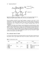
Fig. 13.10. Austenitising a striking face.
142 Engineering Materials 2
The microstructure at position (ii) consisted of grains of ferrite and colonies of
pearlite. It was noticed that the pearlite had started to “spheroidise” (see Problem
5.2). The microstructure at position (i) consisted of grains of ferrite and grains of
lower bainite in roughly equal proportions. Estimate the temperatures to which
the tube been heated at positions (i) and (ii). Explain the reasoning behind your
answers.
Answers: (i) 800°C; (ii) 700°C.
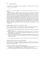
13.2 In 1962 a span of Kings Bridge (Melbourne, Australia) collapsed by brittle frac-
ture. The fracture started from a crack in the heat-affected zone (HAZ) of a
transverse fillet weld, which had been used to attach a reinforcing plate to the
underside of a main structural I-beam (see the diagram on the next page). The
concentrations of the alloying elements in the steel (in weight%) were: C, 0.26;
Mn, 1.80; Cr, 0.25. The welding was done by hand, without any special precau-
tions. The welding electrodes had become damp before use.
Account for the HAZ cracking. After the collapse, the other transverse welds in
the bridge were milled-out and rewelded. What procedures would you specify to
avoid a repeat of the HAZ cracking?
13.3 Steels for railroad rails typically contain 0.80 weight% carbon, 0.3 weight% silicon
and 1.0 weight% manganese. The steel is processed to give a fine-grained pearlitic
structure with a hardness of approximately 2.8 GPa. However, after a period in
service, it is commonly found that a thin, hard layer (the “white layer”) forms in
patches on the top (running) surface of the rail. The microhardness of this white
layer is typically around 8 GPa. Given that frictional heating between the wheels
of rail vehicles and the running surface of the rail can raise the temperature at the
interface to 800°C, explain why the white layer forms and account for its high
hardness.
Transverse
weld
HAZ
Web
σ
σ
76
3
Web
Tension
flange
Crack
Tension flange
Cover plate
Production, forming and joining of metals 143
Chapter 14
Production, forming and joining of metals
Introduction
Figure 14.1 shows the main routes that are used for processing raw metals into finished
articles. Conventional forming methods start by melting the basic metal and then cast-
ing the liquid into a mould. The casting may be a large prism-shaped ingot, or a
continuously cast “strand”, in which case it is worked to standard sections (e.g. sheet,
tube) or forged to shaped components. Shaped components are also made from stand-
ard sections by machining or sheet metalworking. Components are then assembled into
finished articles by joining operations (e.g. welding) which are usually carried out in
conjunction with finishing operations (e.g. grinding or painting). Alternatively, the
casting can be made to the final shape of the component, although some light machin-
ing will usually have to be done on it.
Increasing use is now being made of alternative processing routes. In powder metal-
lurgy the liquid metal is atomised into small droplets which solidify to a fine powder.
The powder is then hot pressed to shape (as we shall see in Chapter 19, hot-pressing is
Fig. 14.1. Processing routes for metals.
144 Engineering Materials 2
the method used for shaping high-technology ceramics). Melt spinning (Chapter 9) gives
high cooling rates and is used to make amorphous alloys. Finally, there are a number
of specialised processes in which components are formed directly from metallic com-
pounds (e.g. electro forming or chemical vapour deposition).
It is not our intention here to give a comprehensive survey of the forming processes
listed in Fig. 14.1. This would itself take up a whole book, and details can be found in
the many books on production technology. Instead, we look at the underlying prin-
ciples, and relate them to the characteristics of the materials that we are dealing with.
Casting
We have already looked at casting structures in Chapter 9. Ingots tend to have the
structure shown in Fig. 14.2. When the molten metal is poured into the mould, chill
crystals nucleate on the cold walls of the mould and grow inwards. But the chill
crystals are soon overtaken by the much larger columnar grains. Finally, nuclei are
swept into the remaining liquid and these grow to produce equiaxed grains at the
centre of the ingot. As the crystals grow they reject dissolved impurities into the re-
maining liquid, causing segregation. This can lead to bands of solid impurities (e.g. iron
sulphide in steel) or to gas bubbles (e.g. from dissolved nitrogen). And because most
metals contract when they solidify, there will be a substantial contraction cavity at the
top of the ingot as well (Fig. 14.2).
These casting defects are not disastrous in an ingot. The top, containing the cavity,
can be cut off. And the gas pores will be squashed flat and welded solid when the
white-hot ingot is sent through the rolling mill. But there are still a number of dis-
advantages in starting with ingots. Heavy segregation may persist through the rolling
operations and can weaken the final product*. And a great deal of work is required to
roll the ingot down to the required section.
* Welded joints are usually in a state of high residual stress, and this can tear a steel plate apart if it happens
to contain layers of segregated impurity.
Fig. 14.2. Typical ingot structure.
Production, forming and joining of metals 145
Fig. 14.3. Continuous casting.
Many of these problems can be solved by using continuous casting (Fig. 14.3). Con-
traction cavities do not form because the mould is continuously topped up with liquid
metal. Segregation is reduced because the columnar grains grow over smaller dis-
tances. And, because the product has a small cross-section, little work is needed to roll
it to a finished section.
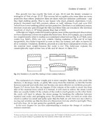
Shaped castings must be poured with much more care than ingots. Whereas the
structure of an ingot will be greatly altered by subsequent working operations, the
structure of a shaped casting will directly determine the strength of the finished article.
Gas pores should be avoided, so the liquid metal must be degassed to remove dissolved
gases (either by adding reactive chemicals or – for high-technology applications –
casting in a vacuum). Feeders must be added (Fig. 14.4) to make up the contraction.
And inoculants should be added to refine the grain size (Chapter 9). This is where
powder metallurgy is useful. When atomised droplets solidify, contraction is immaterial.
Segregation is limited to the size of the powder particles (2 to 150
µ
m); and the small
powder size will give a small grain size in the hot-pressed product.
Shaped castings are usually poured into moulds of sand or metal (Fig. 14.4). The
first operation in sand casting is to make a pattern (from wood, metal or plastic)
shaped like the required article. Sand is rammed around the pattern and the mould is
then split to remove the pattern. Passages are cut through the sand for ingates and
risers. The mould is then re-assembled and poured. When the casting has gone solid it
is removed by destroying the mould. Metal moulds are machined from the solid. They
146 Engineering Materials 2
Fig. 14.4. Sand casting. When the casting has solidified it is removed by destroying the sand mould. The
casting is then “fettled” by cutting off the ingate and the feeder head.
must come apart in enough places to allow the casting to be removed. They are costly,
but can be used repeatedly; and they are ideal for pressure die casting (Fig. 14.5),
which gives high production rates and improved accuracy. Especially intricate cast-
ings cannot be made by these methods: it is impossible to remove a complex pattern
from a sand mould, and impossible to remove a complex casting from a metal one!
This difficulty can be overcome by using investment casting (Fig. 14.6). A wax pattern
is coated with a ceramic slurry. The slurry is dried to give it strength, and is then
fired (as Chapter 19 explains, this is just how we make ceramic cups and plates).
Fig. 14.5. Pressure die casting.
Production, forming and joining of metals 147
Fig. 14.6. Investment casting.
During firing the wax burns out of the ceramic mould to leave a perfectly shaped
mould cavity.
Working processes
The working of metals and alloys to shape relies on their great plasticity: they can be
deformed by large percentages, especially in compression, without breaking. But the
forming pressures needed to do this can be large – as high as 3
σ
y
or even more, depend-
ing on the geometry of the process.
We can see where these large pressures come from by modelling a typical forging
operation (Fig. 14.7). In order to calculate the forming pressure at a given position x
we apply a force f to a movable section of the forging die. If we break the forging up
into four separate pieces we can arrange for it to deform when the movable die sec-
tions are pushed in. The sliding of one piece over another requires a shear stress k (the
shear yield stress). Now the work needed to push the die sections in must equal the
work needed to shear the pieces of the forging over one another. The work done on
each die section is f × u, giving a total work input of 2fu. Each sliding interface has area
2
(d/2)L. The sliding force at each interface is thus
2
(d/2)L × k. Each piece slides a
distance (
2
)u relative to its neighbour. The work absorbed at each interface is thus
2
(d/2)Lk(
2
)u; and there are four interfaces. The work balance thus gives
242224fu d Lk u dLku (/) ( ) ,==
(14.1)
or
f = 2dLk. (14.2)
148 Engineering Materials 2
The forming pressure, p
f
, is then given by
p
f
dL
k
f
y
===2 σ
(14.3)
which is just what we would expect.
We get a quite different answer if we include the friction between the die and the
forging. The extreme case is one of sticking friction: the coefficient of friction is so high
that a shear stress k is needed to cause sliding between die and forging. The total area
between the dies and piece c is given by
2
22
2
W
x
d
Lw xdL
−+
=−− ( ).
(14.4)
Piece c slides a distance 2u relative to the die surfaces, absorbing work of amount
(w − 2x − d)Lk2u. (14.5)
Production, forming and joining of metals 149
Fig. 14.7. A typical forging operation. (a) Overall view. (b) to (d) Modelling the plastic flow. We assume
that flow only takes place in the plane of the drawing. The third dimension, measured perpendicular to the
drawing, is
L
.
Pieces a and b have a total contact area with the dies of 2dL. They slide a distance u
over the dies, absorbing work of amount
2dLku. (14.6)
The overall work balance is now
2fu = 4dLku + 2(w − 2x − d)Lku + 2dLku (14.7)
150 Engineering Materials 2
Fig. 14.8. How the forming pressure varies with position in the forging.
or
fLkd
w
x .=+−
2
2
(14.8)
The forming pressure is then
p
f
dL
wx
d
f
y
(/)
.== +
−
σ 1
2
(14.9)
This equation is plotted in Fig. 14.8: p
f
increases linearly from a value of
σ
y
at the edge
of the die to a maximum of
p
w
d
ymax
=+
σ 1
2
(14.10)
at the centre.
It is a salutory exercise to put some numbers into eqn. (14.10): if w/d = 10, then
p
max
= 6
σ
y
. Pressures of this magnitude are likely to deform the metal-forming tools
themselves – clearly an undesirable state of affairs. The problem can usually be solved
by heating the workpiece to ≈ 0.7 T
m
before forming, which greatly lowers
σ
y
. Or it
may be possible to change the geometry of the process to reduce w/d. Rolling is a good
example of this. From Fig. 14.9 we can write
(r − b)
2
+ w
2
= r
2
. (14.11)
Provided b Ӷ 2r this can be expanded to give
wrb .= 2
(14.12)
Thus
w
d
rb
d
r
d
b
d
/
/
==
22
12
12
. (14.13)
Production, forming and joining of metals 151
Fig. 14.9. (a) In order to minimise the effects of friction, rolling operations should be carried out with
minimum values of
w
/
d
. (b) Small rolls give small
w
/
d
values, but they may need to be supported by
additional secondary rolls.
Well-designed rolling mills therefore have rolls of small diameter. However, as
Fig. 14.9 shows, these may need to be supported by additional secondary rolls which
do not touch the workpiece. In fact, aluminium cooking foil is rolled by primary rolls
the diameter of a pencil, backed up by a total of 18 secondary rolls.
Recovery and recrystallisation
When metals are forged, or rolled, or drawn to wire, they work-harden. After a deforma-
tion of perhaps 80% a limit is reached, beyond which the metal cracks or fractures.
Further rolling or drawing is possible if the metal is annealed (heated to about 0.6 T
m
).
During annealing, old, deformed grains are replaced by new, undeformed grains, and
the working can be continued for a further 80% or so.
152 Engineering Materials 2
Fig. 14.10. How the microstructure of a metal is changed by plastic working and annealing. (a) If the
starting metal has already been annealed it will have a comparatively low dislocation density. (b) Plastic
working greatly increases the dislocation density. (c) Annealing leads initially to recovery – dislocations
move to low-energy positions. (d) During further annealing new grains nucleate and grow. (e) The fully
recrystallised metal consists entirely of new undeformed grains.
Figure 14.10 shows how the microstructure of a metal changes during plastic work-
ing and annealing. If the metal has been annealed to begin with (Fig. 14.10a) it will
have a comparatively low dislocation density (about 10
12
m
−2
) and will be relatively
soft and ductile. Plastic working (Fig. 14.10b) will greatly increase the dislocation
density (to about 10
15
m
−2
). The metal will work-harden and will lose ductility. Because
each dislocation strains the lattice the deformed metal will have a large strain energy
(about 2 MJ m
−3
). Annealing gives the atoms enough thermal energy that they can
move under the driving force of this strain energy. The first process to occur is recovery
(Fig. 14.10c). Because the strain fields of the closely spaced dislocations interact, the
total strain energy can be reduced by rearranging the dislocations into low-angle grain
Production, forming and joining of metals 153
Fig. 14.11. Typical data for recrystallised grain size as a function of prior plastic deformation. Note that,
below a critical deformation, there is not enough strain energy to nucleate the new strain-free grains. This is
just like the critical undercooling needed to nucleate a solid from its liquid (see Fig. 7.4).
boundaries. These boundaries form the surfaces of irregular cells – small volumes
which are relatively free of dislocations. During recovery the dislocation density goes
down only slightly: the hardness and ductility are almost unchanged. The major changes
come from recrystallisation. New grains nucleate and grow (Fig. 14.10d) until the whole
of the metal consists of undeformed grains (Fig. 14.10e). The dislocation density re-
turns to its original value, as do the values of the hardness and ductility.
Recrystallisation is not limited just to getting rid of work-hardening. It is also a
powerful way of controlling the grain size of worked metals. Although single crystals
are desirable for a few specialised applications (see Chapter 9) the metallurgist almost
always seeks a fine grain size. To begin with, fine-grained metals are stronger and
tougher than coarse-grained ones. And large grains can be undesirable for other
reasons. For example, if the grain size of a metal sheet is comparable to the sheet
thickness, the surface will rumple when the sheet is pressed to shape; and this makes
it almost impossible to get a good surface finish on articles such as car-body panels or
spun aluminium saucepans.
The ability to control grain size by recrystallisation is due to the general rule (e.g.
Chapter 11) that the harder you drive a transformation, the finer the structure you get.
In the case of recrystallisation this means that the greater the prior plastic deformation
(and hence the stored strain energy) the finer the recrystallised grain size (Fig. 14.11).
To produce a fine-grained sheet, for example, we simply reduce the thickness by about
50% in a cold rolling operation (to give the large stored strain energy) and then anneal
the sheet in a furnace (to give the fine recrystallised structure).
Machining
Most engineering components require at least some machining: turning, drilling, mill-
ing, shaping, or grinding. The cutting tool (or the abrasive particles of the grinding
154 Engineering Materials 2
Fig. 14.12. Machining.
wheel) parts the chip from the workpiece by a process of plastic shear (Fig. 14.12).
Thermodynamically, all that is required is the energy of the two new surfaces created
when the chip peels off the surface; in reality, the work done in the plastic shear (a
strain of order 1) greatly exceeds this minimum necessary energy. In addition, the
friction is very high (
µ
≈ 0.5) because the chip surface which bears against the tool
is freshly formed, and free from adsorbed films which could reduce adhesion. This
friction can be reduced by generous lubrication with water-soluble cutting fluids, which
also cool the tool. Free cutting alloys have a built-in lubricant which smears across the
tool face as the chip forms: lead in brass, manganese sulphide in steel.
Machining is expensive – in energy, wasted material and time. Forming routes
which minimise or avoid machining result in considerable economies.
Joining
Many of the processes used to join one metal to another are based on casting. We have
already looked at fusion welding (Fig. 13.6). The most widely used welding process is
arc welding: an electric arc is struck between an electrode of filler metal and the
workpieces, providing the heat needed to melt the filler and fuse it to the parent
plates. The electrode is coated with a flux which melts and forms a protective cover on
the molten metal. In submerged arc welding, used for welding thick sections automatic-
ally, the arc is formed beneath a pool of molten flux. In gas welding the heat source is
an oxyacetylene flame. In spot welding the metal sheets to be joined are pressed to-
gether between thick copper electrodes and fused together locally by a heavy current.
Small, precise welds can be made using either an electron beam or a laser beam as the
heat source.
Production, forming and joining of metals 155
Brazing and soldering are also fine-scale casting processes. But they use filler metals
which melt more easily than the parent metal (see Table 4.1). The filler does not join to
the parent metal by fusion (melting together). Instead, the filler spreads over, or wets,
the solid parent metal and, when it solidifies, becomes firmly stuck to it. True metal-to-
metal contact is essential for good wetting. Before brazing, the parent surfaces are
either mechanically abraded or acid pickled to remove as much of the surface oxide
film as possible. Then a flux is added which chemically reduces any oxide that forms
during the heating cycle. Specialised brazing operations are done in a vacuum furnace
which virtually eliminates oxide formation.
Adhesives, increasingly used in engineering applications, do not necessarily require
the application of heat. A thin film of epoxy, or other polymer, is spread on the
surfaces to be joined, which are then brought together under pressure for long enough
for the adhesive to polymerise or set. Special methods are required with adhesives, but
they offer great potential for design.
Metal parts are also joined by a range of fasteners: rivets, bolts, or tabs. In using
them, the stress concentration at the fastener or its hole must be allowed for: fracture
frequently starts at a fastening point.
Surface engineering
Often it is the properties of a surface which are critical in an engineering application.
Examples are components which must withstand wear; or exhibit low friction; or resist
oxidation or corrosion. Then the desired properties can often be achieved by creating a
thin surface layer with good (but expensive) properties on a section of poorer (but
cheaper) metal, offering great economies of production.
Surface treatments such as carburising or nitriding give hard surface layers, which
give good wear and fatigue resistance. In carburising, a steel component is heated into
the austenite region. Carbon is then diffused into the surface until its concentration
rises to 0.8% or more. Finally the component is quenched into oil, transforming the
surface into hard martensite. Steels for nitriding contain aluminium: when nitrogen
is diffused into the surface it reacts to form aluminium nitride, which hardens the
surface by precipitation hardening. More recently ion implantation has been used: for-
eign ions are accelerated in a strong electric field and are implanted into the surface.
Finally, laser heat treatment has been developed as a powerful method for producing
hard surfaces. Here the surface of the steel is scanned with a laser beam. As the beam
passes over a region of the surface it heats it into the austenite region. When the beam
passes on, the surface it leaves behind is rapidly quenched by the cold metal beneath
to produce martensite.
Energy-efficient forming
Many of the processes used for working metals are energy-intensive. Large amounts
of energy are needed to melt metals, to roll them to sections, to machine them or to
weld them together. Broadly speaking, the more steps there are between raw metal
156 Engineering Materials 2
and finished article (see Fig. 14.1) then the greater is the cost of production. There is
thus a big incentive to minimise the number of processing stages and to maximise the
efficiency of the remaining operations. This is not new. For centuries, lead sheet for
organ pipes has been made in a single-stage casting operation. The Victorians were the
pioneers of pouring intricate iron castings which needed the minimum of machining.
Modern processes which are achieving substantial energy savings include the single-
stage casting of thin wires or ribbons (melt spinning, see Chapter 9) or the spray
deposition of “atomised” liquid metal to give semi-finished seamless tubes. But modi-
fications of conventional processes can give useful economies too. In examining a
production line it is always worth questioning whether a change in processing method
could be introduced with economic benefits.
Background reading
M. F. Ashby and D. R. H. Jones, Engineering Materials I, 2nd edition, Butterworth-Heinemann, 1996.
Further reading
S. Kalpakjian, Manufacturing Processes for Engineering Materials, Addison-Wesley, 1984.
J. A. Schey, Introduction to Manufacturing Processes, McGraw-Hill Kogakusha, 1977.
J. M. Alexander and R. C. Brewer, Manufacturing Properties of Materials, Van Nostrand, 1968.
G. J. Davies, Solidification and Casting, Applied Science Publishers, 1973.
C. R. Calladine, Plasticity for Engineers, Ellis Horwood, 1985.
G. Parrish and G. S. Harper, Production Gas Carburising, Pergamon, 1985.
J. Campbell, Castings, Butterworth-Heinemann, 1991.
Problems
14.1 Estimate the percentage volume contraction due to solidification in pure copper.
Use the following data: T
m
= 1083°C; density of solid copper at 20°C = 8.96 Mg m
–3
;
average coefficient of thermal expansion in the range 20 to 1083°C = 20.6 M K
–1
;
density of liquid copper at T
m
= 8.00 Mg m
–3
.
Answer: 5%.
14.2 A silver replica of a holly leaf is to be made by investment casting. (A natural leaf
is coated with ceramic slurry which is then dried and fired. During firing the leaf
burns away, leaving a mould cavity.) The thickness of the leaf is 0.4 mm. Calcu-
late the liquid head needed to force the molten silver into the mould cavity. It can
be assumed that molten silver does not wet the mould walls.
[Hint: the pressure needed to force a non-wetting liquid into a parallel-sided
cavity of thickness t is given by
p
T
t
(/ )
=
2
Production, forming and joining of metals 157
where T is the surface tension of the liquid.] The density and surface tension of
molten silver are 9.4 Mg m
–3
and 0.90 Nm
–1
.
Answer: 49 mm.
14.3 Aluminium sheet is to be rolled according to the following parameters: starting
thickness 1 mm, reduced thickness 0.8 mm, yield strength 100 MPa. What roll
radius should be chosen to keep the forming pressure below 200 MPa?
Answer: 16.2 mm, or less.
14.4 Aluminium sheet is to be rolled according to the following parameters: sheet
width 300 mm, starting thickness 1 mm, reduced thickness 0.8 mm, yield strength
100 MPa, maximum forming pressure 200 MPa, roll radius 16.2 mm, roll length
300 mm. Calculate the force F that the rolling pressure will exert on each roll.
[Hint: use the average forming pressure, p
av
, shown in Fig. 14.8.]
The design states that the roll must not deflect by more than 0.01 mm at its
centre. To achieve this bending stiffness, each roll is to be backed up by one
secondary roll as shown in Fig. 14.9(b). Calculate the secondary roll radius needed
to meet the specification. The central deflection of the secondary roll is given by
δ
=
5
384
3
FL
EI
where L is the roll length and E is the Young’s modulus of the roll material. I, the
second moment of area of the roll section, is given by
Ir /=
π
s
4
4
where r
s
is the secondary roll radius. The secondary roll is made from steel, with
E = 210 GPa. You may neglect the bending stiffness of the primary roll.
Answers: F = 81 kN; r
s
= 64.5 mm.
14.5 Copper capillary fittings are to be used to solder copper water pipes together as
shown below:
The joint is designed so that the solder layer will yield in shear at the same axial
load F that causes the main tube to fail by tensile yield. Estimate the required
value of W, given the following data: t = 1 mm;
σ
y
(copper) = 120 MPa;
σ
y
(solder)
= 10 MPa.
Answer: 24 mm.
F
w
F
r
†
Solder layer
158 Engineering Materials 2
14.6 A piece of plain carbon steel containing 0.2 wt% carbon was case-carburised to
give a case depth of 0.3 mm. The carburising was done at a temperature of
1000°C. The Fe–C phase diagram shows that, at this temperature, the iron can
dissolve carbon to a maximum concentration of 1.4 wt%. Diffusion of carbon
into the steel will almost immediately raise the level of carbon in the steel to a
constant value of 1.4 wt% just beneath the surface of the steel. However, the
concentration of carbon well below the surface will increase more slowly towards
the maximum value of 1.4 wt% because of the time needed for the carbon to
diffuse into the interior of the steel.
The diffusion of carbon into the steel is described by the time-dependent diffu-
sion equation
Cxt C C
x
Dt
C
s
( , ) ( ) .=− −
+
00
1
2
erf
The symbols have the meanings: C, concentration of carbon at a distance x below
the surface after time t; C
s
, 1.4 wt% C; C
0
, 0.2 wt% C; D, diffusion coefficient for
carbon in steel. The “error function”, erf(y), is given by
erf e d() .yZ
Z
y
=
−
∫
2
2
0
π
The following table gives values for this integral.
y 0 0.1 0.2 0.3 0.4 0.5 0.6 0.7
erf(y) 0 0.11 0.22 0.33 0.43 0.52 0.60 0.68
y 0.8 0.9 1.0 1.1 1.2 1.3 1.4 1.5 ∞
erf(y) 0.74 0.80 0.84 0.88 0.91 0.93 0.95 0.97 1.00
The diffusion coefficient may be taken as
D
RT
exp
=×
−
−−
−
910
125
621
1
m s
kJ mol
where R is the gas constant and T is the absolute temperature.
Calculate the time required for carburisation, if the depth of the case is taken to
be the value of x for which C = 0.5 wt% carbon.
Answer: 8.8 minutes.
Ceramics and glasses 159
B. Ceramics and glasses
160 Engineering Materials 2
Ceramics and glasses 161
Chapter 15
Ceramics and glasses
Introduction
If you have ever dropped a plate on the kitchen floor and seen it disintegrate, you
might question whether ceramics have a role as load-bearing materials in engineering.
But any friend with a historical perspective will enlighten you. Ceramic structures are
larger and have survived longer than any other works. The great pyramid of Giza is
solid ceramic (nearly 1,000,000 tonnes of it); so is the Parthenon, the Forum, the Great
Wall of China. The first cutting tools and weapons were made of flint – a glass; and
pottery from 5000 bc survives to the present day. Ceramics may not be as tough as
metals, but for resistance to corrosion, wear, decay and corruption, they are unsurpassed.
Today, cement and concrete replace stone in most large structures. But cement, too,
is a ceramic: a complicated but fascinating one. The understanding of its structure, and
how it forms, is better now than it used to be, and has led to the development of
special high-strength cement pastes which can compete with polymers and metals in
certain applications.
But the most exciting of all is the development, in the past 20 years, of a range of
high-performance engineering ceramics. They can replace, and greatly improve on,
metals in many very demanding applications. Cutting tools made of sialons or of
dense alumina can cut faster and last longer than the best metal tools. Engineering
ceramics are highly wear-resistant: they are used to clad the leading edges of agri-
cultural machinery like harrows, increasing the life by 10 times. They are inert and
biocompatible, so they are good for making artificial joints (where wear is a big prob-
lem) and other implants. And, because they have high melting points, they can stand
much higher temperatures than metals can: vast development programs in Japan, the
US and Europe aim to put increasing quantities of ceramics into reciprocating engines,
turbines and turbochargers. In the next decade the potential market is estimated at
$1 billion per year. Even the toughness of ceramics has been improved: modern body-
armour is made of plates of boron carbide or of alumina, sewn into a fabric vest.
The next six chapters of this book focus on ceramics and glasses: non-metallic,
inorganic solids. Five classes of materials are of interest to us here:
(a) Glasses, all of them based on silica (SiO
2
), with additions to reduce the melting
point, or give other special properties.
(b) The traditional vitreous ceramics, or clay products, used in vast quantities for plates
and cups, sanitary ware, tiles, bricks, and so forth.
(c) The new high-performance ceramics, now finding application for cutting tools, dies,
engine parts and wear-resistant parts.
162 Engineering Materials 2
(d) Cement and concrete: a complex ceramic with many phases, and one of three essen-
tial bulk materials of civil engineering.
(e) Rocks and minerals, including ice.
As with metals, the number of different ceramics is vast. But there is no need to
remember them all: the generic ceramics listed below (and which you should re-
member) embody the important features; others can be understood in terms of these.
Although their properties differ widely, they all have one feature in common: they
are intrinsically brittle, and it is this that dictates the way in which they can be used.
They are, potentially or actually, cheap. Most ceramics are compounds of oxygen,
carbon or nitrogen with metals like aluminium or silicon; all five are among the most
plentiful and widespread elements in the Earth’s crust. The processing costs may be
high, but the ingredients are almost as cheap as dirt: dirt, after all, is a ceramic.
The generic ceramics and glasses
Glasses
Glasses are used in enormous quantities: the annual tonnage is not far below that of
aluminium. As much as 80% of the surface area of a modern office block can be glass;
and glass is used in a load-bearing capacity in car windows, containers, diving bells
and vacuum equipment. All important glasses are based on silica (SiO
2
). Two are of
primary interest: common window glass, and the temperature-resisting borosilicate
glasses. Table 15.1 gives details.
Table 15.1. Generic glasses
Glass Typical composition (wt%) Typical uses
Soda-lime glass 70 SiO
2
, 10 CaO, 15 Na
2
O Windows, bottles, etc.; easily formed and shaped.
Borosilicate glass 80 SiO
2
, 15 B
2
O
3
, 5 Na
2
O Pyrex; cooking and chemical glassware; high-
temperature strength, low coefficient of
expansion, good thermal shock resistance.
Vitreous ceramics
Potters have been respected members of society since ancient times. Their products
have survived the ravages of time better than any other; the pottery of an era or civilisa-
tion often gives the clearest picture of its state of development and its customs. Mod-
ern pottery, porcelain, tiles, and structural and refractory bricks are made by processes
which, though automated, differ very little from those of 2000 years ago. All are made
from clays, which are formed in the wet, plastic state and then dried and fired. After
firing, they consist of crystalline phases (mostly silicates) held together by a glassy
phase based, as always, on silica (SiO
2
). The glassy phase forms and melts when the
clay is fired, and spreads around the surface of the inert, but strong, crystalline phases,
bonding them together. The important information is summarised in Table 15.2.
Ceramics and glasses 163
Table 15.2. Generic vitreous ceramics
Ceramic Typical composition Typical uses
Porcelain Made from clays: hydrous Electrical insulators.
China alumino-silicate such as Artware and
Pottery Al
2
(Si
2
O
5
)(OH)
4
mixed with other inert tableware tiles.
Brick minerals. Construction; refractory uses.
Table 15.3. Generic high-performance ceramics
Ceramic Typical composition Typical uses
Dense alumina Al
2
O
3
Cutting tools, dies; wear-resistant surfaces, bearings;
Silicon carbide, nitride SiC, Si
3
N
4
medical implants; engine and turbine parts; armour.
Sialons e.g. Si
2
AlON
3
Cubic zirconia ZrO
2
+ 5wt% MgO
Table 15.4. Generic cements and concretes
Cement Typical composition Uses
Portland cement CaO + SiO
2
+ Al
2
O
3
Cast facings, walkways, etc. and as component of concrete.
General construction.
High-performance engineering ceramics
Diamond, of course, is the ultimate engineering ceramic; it has for many years been used
for cutting tools, dies, rock drills, and as an abrasive. But it is expensive. The strength
of a ceramic is largely determined by two characteristics: its toughness (K
IC
), and the
size distribution of microcracks it contains. A new class of fully dense, high-strength
ceramics is now emerging which combine a higher K
IC
with a much narrower distribu-
tion of smaller microcracks, giving properties which make them competitive with
metals, cermets, even with diamond, for cutting tools, dies, implants and engine parts.
And (at least potentially) they are cheap. The most important are listed in Table 15.3.
Cement and concrete
Cement and concrete are used in construction on an enormous scale, equalled only by
structural steel, brick and wood. Cement is a mixture of a combination of lime (CaO),
silica (SiO
2
) and alumina (Al
2
O
3
), which sets when mixed with water. Concrete is sand
and stones (aggregate) held together by a cement. Table 15.4 summarises the most
important facts.
Natural ceramics
Stone is the oldest of all construction materials and the most durable. The pyramids
are 5000 years old; the Parthenon 2200. Stone used in a load-bearing capacity behaves
164 Engineering Materials 2
Table 15.5. Generic natural ceramics
Ceramic Composition Typical uses
Limestone (marble) Largely CaCO
3
5
Sandstone Largely SiO
2
6Building foundations, construction.
Granite Aluminium silicates 7
Ice H
2
O Arctic engineering.
Table 15.6. Ceramic composites
Ceramic composite Components Typical uses
Fibre glass Glass–polymer #High-performance structures.
CFRP Carbon–polymer
$
Cermet Tungsten carbide–cobalt Cutting tools, dies.
Bone Hydroxyapatite–collagen Main structural material of animals.
New ceramic composites Alumina–silicon carbide High temperature and high toughness applications.
Table 15.7. Properties of ceramics
Ceramic Cost Density Young’s Compressive Modulus Weibull
(UK£ (US$) (Mg m
−
3
) modulus strength of rupture exponent
tonne
−
1
) (GPa) (MPa) (MPa) m
Glasses
Soda glass 700 (1000) 2.48 74 1000 50 5
Assume 10
Borosilicate glass 1000 (1400) 2.23 65 1200 55 4
in design
Pottery, etc
.
6
Porcelain 260–1000 2.3–2.5 70 350 45
4
(360–1400)
7
High-performance
engineering
ceramics
Diamond 4 × 10
8
(6 × 10
8
) 3.52 1050 5000 –
Dense alumina Expensive at 3.9 380 3000 300–400 10
Silicon carbide present. 3.2 410 2000 200–500 10
Silicon nitride Potentially 3.2 310 1200 300–850 –
Zirconia 350–1000 5.6 200 2000 200–500 10–21
Sialons (490–1400) 3.2 300 2000 500–830 15
Cement, etc
.
Cement 52 (73) 2.4–2.5 20–30 50 7 12
Concrete 26 (36) 2.4 30–50 50 7 12
Rocks and ice
Limestone Cost of mining 2.7 63 30–80 20 –
Granite and transport 2.6 60–80 65–150 23 –
Ice 0.92 9.1 6 1.7 –
Ceramics and glasses 165
like any other ceramic; and the criteria used in design with stone are the same. One
natural ceramic, however, is unique. Ice forms on the Earth’s surface in enormous
volumes: the Antarctic ice cap, for instance, is up to 3 km thick and almost 3000 km
across; something like 10
13
m
3
of pure ceramic. The mechanical properties are of primary
importance in some major engineering problems, notably ice breaking, and the con-
struction of offshore oil rigs in the Arctic. Table 15.5 lists the important natural ceramics.
Ceramic composites
The great stiffness and hardness of ceramics can sometimes be combined with the
toughness of polymers or metals by making composites. Glass- and carbon-fibre rein-
forced plastics are examples: the glass or carbon fibres stiffen the rather floppy poly-
mer; but if a fibre fails, the crack runs out of the fibre and blunts in the ductile polymer
without propagating across the whole section. Cermets are another example: particles
of hard tungsten carbide bonded by metallic cobalt, much as gravel is bonded with tar
to give a hard-wearing road surface (another ceramic-composite). Bone is a natural
ceramic-composite: particles of hydroxyapatite (the ceramic) bonded together by col-
lagen (a polymer). Synthetic ceramic–ceramic composites (like glass fibres in cement,
or silicon carbide fibres in silicon carbide) are now under development and may have
important high-temperature application in the next decade. The examples are summar-
ised in Table 15.6.
Time Fracture Melting Specific Thermal Thermal Thermal shock
exponent toughness (softening) heat conductivity expansion resistance
n (MPa m
1/2
) temperature (J kg
−
1
K
−
1
) (W m
−
1
K
−
1
) coefficient (K)
(K) (MK
−
1
)
10 0.7 (1000) 990 1 8.5 84
10 0.8 (1100) 800 1 4.0 280
– 1.0 (1400) 800 1 3 220
–– – 510 70 1.2 1000
10 3–5 2323 (1470) 795 25.6 8.5 150
40 – 3110 – 1422 84 4.3 300
40 4 2173 – 627 17 3.2 500
10 4–12 2843 – 670 1.5 8 500
10 5 –– 710 20–25 3.2 510
40 0.2 ––1.8 10–14 #
<50
40 0.2 ––210–14
$
– 0.9 –––8 #
≈100
––– ––8
$
– 0.12 273 (250) –––