Engineering Materials Vol II (microstructures processing design) 2nd ed. - M. Ashby_ D. Jones (1999) Episode 8 ppt
Bạn đang xem bản rút gọn của tài liệu. Xem và tải ngay bản đầy đủ của tài liệu tại đây (609.02 KB, 30 trang )
Production, forming and joining of ceramics 201
15 minutes. Most glass products are held briefly at this temperature to remove tensile
stresses that might otherwise induce fracture. At the strain point (
η
= 10
14
poise) atom
motion in the glass is so sluggish that rapid cooling from this temperature does not
introduce new stresses. So, in processing, the product is cooled slowly from the an-
nealing point to the strain point and faster from there to room temperature.
Residual tensile stresses, as we have seen, are a problem. But compressive residual
stresses, in the right place, can be used to advantage. Toughened glass is made by
heating the product above its annealing point, and then cooling rapidly. The surface
contracts and hardens while the interior is still hot and more fluid; it deforms, allow-
ing the tensile stress in the surface to relax. Then the interior cools and contracts. But
the surface is below its strain point; it cannot flow, so it is put into compression by the
contracting interior. With the surface in compression, the glass is stronger, because the
microcracks which initiate failure in a glass are always in the surface (caused by
abrasion or corrosion). The interior, of course, is in tension; and if a crack should
penetrate through the protective compressive layer it is immediately unstable and the
toughened glass shatters spontaneously.
The production and forming of pottery, porcelain and brick
Pottery is one of the oldest materials. Clay artefacts as old as the pyramids (5000 bc)
are sophisticated in their manufacture and glazing; and shards of pottery of much
earlier date are known. Then, as now, the clay was mined from sites where weathering
had deposited them, hydroplastically formed, fired and then glazed.
Clays have plate-like molecules with charges on their surfaces (Chapter 16). The
charges draw water into the clay as a thin lubricating layer between the plates. With
the right moisture content, clays are plastic: they can be moulded, extruded, turned or
carved. But when they are dried, they have sufficient strength to be handled and
stacked in kilns for firing.
In slip casting a thin slurry, or suspension, of clay in water is poured into a porous
mould. Water is absorbed into the mould wall, causing a layer of clay to form and
adhere to it. The excess slurry is tipped out of the mould and the slip-cast shell, now
dry enough to have strength, is taken out and fired. The process allows intricate
shapes (like plates, cups, vases) to be made quickly and accurately.
When a clay is fired, the water it contains is driven off and a silicate glass forms by
reaction between the components of the clay. The glass melts and is drawn by surface
tension into the interstices between the particles of clay, like water into a sponge.
Clays for brick and pottery are usually a blend of three constituents which occur
together naturally: pure clay, such as the Al
2
O
3
2SiO
2
2H
2
O (kaolinite) described in
Chapter 16; a flux (such as feldspar) which contains the Na or K used to make the
glass; and a filler such as quartz sand, which reduces shrinkage but otherwise plays no
role in the firing. Low-fire clays contain much flux and can be fired at 1000°C. High-
fire clays have less, and require temperatures near 1200°C. The final microstructure
shows particles of filler surrounded by particles of mullite (the reaction product of
SiO
2
and Al
2
O
3
in the clay) all bonded together by the glass.
202 Engineering Materials 2
Vitreous ceramics are made waterproof and strengthened by glazing. A slurry of
powdered glass is applied to the surface by spraying or dipping, and the part is refired
at a lower temperature (typically 800°C). The glass melts, flows over the surface, and is
drawn by capillary action into pores and microcracks, sealing them.
Improving the performance of ceramics
When we speak of the “strength” of a metal, we mean its yield strength or tensile
strength; to strengthen metals, they are alloyed in such a way as to obstruct dislocation
motion, and thus raise the yield strength. By contrast, the “strength” of a ceramic is its
fracture strength; to strengthen ceramics, we must seek ways of making fracture more
difficult.
There are two, and they are complementary. The tensile fracture strength (Chapter 17) is
roughly
σ
π
TS
IC
=
K
a
(19.8)
and the compressive strength is about 15 times this value. First, we can seek to reduce
the inherent flaw size, a; and second (though this is more difficult) we can seek to
increase the fracture toughness, K
IC
.
Most ceramics (as we have seen) contain flaws: holes and cracks left by processing,
cracks caused by thermal stress, corrosion or abrasion. Even if there are no cracks to
start with, differences in elastic moduli between phases will nucleate cracks on load-
ing. And most of these flaws have a size which is roughly that of the powder particles
from which the ceramic was made. If the flaw size can be reduced, or if samples
containing abnormally large flaws can be detected and rejected, the mean strength of
the ceramic component is increased.
This is largely a problem of quality control. It means producing powders of a control-
led, small size; pressing and sintering them under tightly controlled conditions to
avoid defects caused by poor compaction, or by grain growth; and careful monitoring
of the product to detect any drop in standard. By these methods, the modulus of
rupture for dense Al
2
O
3
and silicon carbide can be raised to 1000 MPa, making them as
strong in tension as a high-strength steel; in compression they are 15 times stronger
again.
The other alternative is to attempt to increase K
IC
. Pure ceramics have a fracture
toughness between 0.2 and 2 MPa m
1/2
. A dispersion of particles of a second phase can
increase this a little: the advancing crack is pinned by the particles and bows between
them, much as a dislocation is pinned by strong second phase particles (Chapter 10).
A more complicated, and more effective, mechanism operates in partially stabilised
zirconia (PSZ), which has general application to other ceramics. Consider the analogy
of a chocolate bar. Chocolate is a brittle solid and because of this it is notch-sensitive:
notches are moulded into chocolate to help you break it in a fair, controlled way. Some
chocolate bars have raisins and nuts in them, and they are less brittle: a crack, when it
Production, forming and joining of ceramics 203
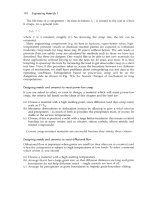
Fig. 19.10. A cermet is a particulate composite of a ceramic (WC) in a metal (Co). A crack in the ceramic
is arrested by plasticity in the cobalt.
runs into a raisin, is arrested; and more energy is needed to break the bar in half. PSZ
works in rather the same way. When ZrO
2
is alloyed with MgO, a structure can be
created which has small particles of tetragonal zirconia (the raisins). When a crack
approaches a particle, the particle transforms by a displacive transformation to a new
(monoclinic) crystal structure, and this process absorbs energy. The details are complic-
ated, but the result is simple: the toughness is increased from 2 to 8 MPa m
1/2
. This
may not seem much compared with 100 MPa m
1/2
for a tough steel, but it is big for a
ceramic, dramatically increasing its strength and resistance to thermal shock, and open-
ing up new applications for it.
Ceramics can be fibre-strengthened to improve their toughness. The plaster in old
houses contains horse hair; and from the earliest times straw has been put into mud
brick, in both cases to increase the toughness. In Arctic regions, ice is used for aircraft
runways; the problem is that heavy aircraft knock large chips out of the brittle surface.
One solution is to spread sawdust or straw onto the surface, flood it with water, and
refreeze it; the fibres toughen the ice and reduce cracking. More recently, methods
have been developed to toughen cement with glass fibres to produce high-strength
panels and pipes. The details of the toughening mechanisms are the same as those for
fibre-reinforced polymers, which we will discuss in Chapter 25. The effect can be
spectacular: toughnesses of over 10 MPa m
1/2
are possible.
An older and successful way of overcoming the brittleness of ceramics is to make a
sort of composite called a cermet. The best example is the cemented carbide used for
cutting tools. Brittle particles of tungsten carbide (WC) are bonded together with a film
of cobalt (Co) by sintering the mixed powders. If a crack starts in a WC particle, it
immediately runs into the ductile cobalt film, which deforms plastically and absorbs
energy (Fig. 19.10). The composite has a fracture toughness of around 15 MPa m
1/2
,
even though that of the WC is only 1 MPa m
1/2
.
The combination of better processing to give smaller flaws with alloying to improve
toughness is a major advance in ceramic technology. The potential, not yet fully real-
ised, appears to be enormous. Table 19.1 lists some of the areas in which ceramics
have, or may soon replace other materials.
204 Engineering Materials 2
Table 19.1 Applications of high-performance ceramics
Application Property Material
Cutting tools Hardness, toughness Alumina, sialons
Bearings, liners, seals Wear resistance Alumina, zirconia
Agricultural machinery Wear resistance Alumina, zirconia
Engine and turbine parts, Heat and wear resistance SiC, Si
3
N
4
, alumina, sialons,
burner nozzles ceramic–ceramic composites
Shielding, armour Hardness, toughness Alumina, boron carbide
High-performance windows Translucence and strength Alumina, magnesia
Artificial bone, teeth, joints Wear resistance, strength Zirconia, alumina
Integrated circuit substrates Insulation, heat resistance Alumina, magnesia
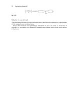
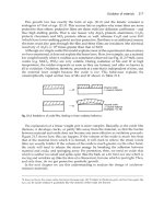
Fig. 19.11. Joining methods for ceramics: (a) glaze bonding, (b) diffusion bonding, (c) metallisation plus
brazing. In addition, ceramics can be clamped, and can be joined with adhesives.
Joining of ceramics
Ceramics cannot be bolted or riveted: the contact stresses would cause brittle failure.
Instead, ceramic components are bonded to other ceramic or metal parts by techniques
which avoid or minimise stress concentrations.
Two such techniques are diffusion bonding and glaze bonding (Fig. 19.11). In diffusion
bonding, the parts are heated while being pressed together; then, by processes like
those which give sintering, the parts bond together. Even dissimilar materials can be
bonded in this way. In glaze bonding the parts are coated with a low-melting (600°C)
glass; the parts are placed in contact and heated above the melting point of the glass.
Ceramics are joined to metals by metal coating and brazing, and by the use of adhes-
ives. In metal coating, the mating face of the ceramic part is coated in a thin film of a
refractory metal such as molybdenum (usually applied as a powder and then heated).
Production, forming and joining of ceramics 205
Purified compounds:
Al
2
O
3
, ZrO
2
, Si etc.
Clays plus fillers
Silica sand plus additives
Mix in pug mill
Blend powders
Hydroplastic forming
Slip casting
Firing
Roll
Extrude
Press
Blow-mould
Finish:
Glazing
Finish:
Grinding, polishing
Joining: Clamps (with soft facing); Adhesives; Cements; Glaze bonding; Diffusion bonding; Metal plate and braze
Finish:
Grinding, polishing,
laser machining
Sinter, press
HIP
Liquid-phase
firing
Reaction-
sinter
Vapour
deposition
Powders
Volatile
compounds
Table 19.2 Forming and joining of ceramics
The metal film is then electroplated with copper, and the metal part brazed to the
copper plating. Adhesives, usually epoxy resins, are used to join parts at low tem-
peratures. Finally, ceramic parts can be clamped together, provided the clamps avoid
stress concentrations, and are provided with soft (e.g. rubber) packing to avoid contact
stresses.
The forming and joining of ceramics is summarised in the flowchart of Table 19.2.
Further reading
D. W. Richardson, Modern Ceramic Engineering, Marcel Dekker, 1982.
Articles in the New Scientist, 26 January 1984 (no. 1394): “Ceramics move from tea cups to
turbines”.
Problems
19.1 You have been given samples of the following ceramics.
(a) A hot-pressed thermocouple sheath of pure alumina.
(b) A piece of window glass.
(c) An unglazed fired clay pot.
(d) A tungsten-carbide/cobalt cutting tool.
206 Engineering Materials 2
Sketch the structures that you would expect to see if you looked at polished
sections of the samples under a reflecting light microscope. Label the phases and
any other features of interest.
19.2 Describe briefly how the tensile strength of ceramic materials is determined by
their microstructures. How may the tensile strength of ceramics be improved?
19.3 Describe the stages which might typically be followed in producing a small steel
gear wheel by powder processing. Discuss the relative advantages and disadvan-
tages of producing the gear wheel by powder processing or machining.
19.4 Why are special precautions necessary when joining ceramic components to metal
components? What methods are available for the satisfactory joining of ceramics
to metals?
Special topic: cements and concretes 207
Chapter 20
Special topic: cements and concretes
Introduction
Concrete is a particulate composite of stone and sand, held together by an adhesive. The
adhesive is usually a cement paste (used also as an adhesive to join bricks or stones),
but asphalt or even polymers can be used to give special concretes. In this chapter
we examine three cement pastes: the primitive pozzolana; the widespread Portland
cement; and the newer, and somewhat discredited, high-alumina cement. And we con-
sider the properties of the principal cement-based composite, concrete. The chemistry
will be unfamiliar, but it is not difficult. The properties are exactly those expected of a
ceramic containing a high density of flaws.
Chemistry of cements
Cement, of a sort, was known to the ancient Egyptians and Greeks. Their lime-cement
was mixed with volcanic ash by the Romans to give a lime mortar; its success can be
judged by the number of Roman buildings still standing 2000 years later. In countries
which lack a sophisticated manufacturing and distribution system, these pozzolana
cements are widely used (they are named after Pozzuoli, near Naples, where the ash
came from, and which is still subject to alarming volcanic activity). To make them,
chalk is heated at a relatively low temperature in simple wood-fired kilns to give lime
Chalk (CaCO
3
)
Heat
C
→
°600
Lime (CaO). (20.1)
The lime is mixed with water and volcanic ash and used to bond stone, brick, or even
wood. The water reacts with lime, turning it into Ca(OH)
2
; but in doing so, a surface
reaction occurs with the ash (which contains SiO
2
) probably giving a small mount of
(CaO)
3
(SiO
2
)
2
(H
2
O)
3
and forming a strong bond. Only certain volcanic ashes have an
active surface which will bond in this way; but they are widespread enough to be
readily accessible.
The chemistry, obviously, is one of the curses of the study of cement. It is greatly
simplified by the use of a reduced nomenclature. The four ingredients that matter in any
cement are, in this nomenclature
Lime CaO = C
Alumina Al
2
O
3
= A
Silica SiO
2
= S
Water H
2
O = H.
208 Engineering Materials 2
Fig. 20.1. A pozzolana cement. The lime (C) reacts with silica (S) in the ash to give a bonding layer of
tobomorite gel C
3
S
2
H
3
.
The key product, which bonds everything together, is
Tobomorite gel (CaO)
3
(SiO
2
)
2
(H
2
O)
3
= C
3
S
2
H
3
.
In this terminology, pozzolana cement is C mixed with a volcanic ash which has active
S on its surface. The reactions which occur when it sets (Fig. 20.1) are
C + H → CH (in the bulk) (20.2)
and
3C + 2S + 3H → C
3
S
2
H
3
(on the pozzolana surface). (20.3)
The tobomorite gel bonds the hydrated lime (CH) to the pozzolana particles. These
two equations are all you need to know about the chemistry of pozzolana cement.
Those for other cements are only slightly more complicated.
The world’s construction industry thrived on lime cements until 1824, when a Leeds
entrepreneur, Jo Aspdin, took out a patent for “a cement of superior quality, resem-
bling Portland stone” (a white limestone from the island of Portland). This Portland
cement is prepared by firing a controlled mixture of chalk (CaCO
3
) and clay (which is
just S
2
AH
2
) in a kiln at 1500°C (a high temperature, requiring special kiln materials
and fuels, so it is a technology adapted to a developed country). Firing gives three
products
Chalk + Clay
Heat
C
→
°1500
C
3
A + C
2
S + C
3
S. (20.4)
When Portland cement is mixed with water, it hydrates, forming hardened cement
paste (“h.c.p.”). All cements harden by reaction, not by drying; indeed, it is important
to keep them wet until full hardness is reached. Simplified a bit, two groups of reac-
tions take place during the hydration of Portland cement. The first is fast, occurring in
the first 4 hours, and causing the cement to set. It is the hydration of the C
3
A
C
3
A + 6H → C
3
AH
6
+ heat. (20.5)
The second is slower, and causes the cement to harden. It starts after a delay of
10 hours or so, and takes 100 days or more before it is complete. It is the hydration of
C
2
S and C
3
S to tobomorite gel, the main bonding material which occupies 70% of the
structure
Special topic: cements and concretes 209
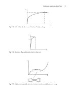
Fig. 20.2. (a) The hardening of Portland cement. The setting reaction (eqn. 20.5) is followed by the
hardening reactions (eqns 20.6 and 20.7). Each is associated with the evolution of heat (b).
2C
2
S + 4H → C
3
S
2
H
3
+ CH + heat (20.6)
2C
3
S + 6H → C
3
S
2
H
3
+ 3CH + heat. (20.7)
d
Tobomorite gel.
Portland cement is stronger than pozzolana because gel forms in the bulk of the
cement, not merely at its surface with the filler particles. The development of strength
is shown in Fig. 20.2(a). The reactions give off a good deal of heat (Fig. 20.2b). It is
used, in cold countries, to raise the temperature of the cement, preventing the water it
contains from freezing. But in very large structures such as dams, heating is a prob-
lem: then cooling pipes are embedded in the concrete to pump the heat out, and left in
place afterwards as a sort of reinforcement.
High-alumina cement is fundamentally different from Portland cement. As its name
suggests, it consists mainly of CA, with very little C
2
S or C
3
S. Its attraction is its high
hardening rate: it achieves in a day what Portland cement achieves in a month. The
hardening reaction is
CA + 10H → CAH
10
+ heat. (20.8)
But its long-term strength can be a problem. Depending on temperature and environ-
ment, the cement may deteriorate suddenly and without warning by “conversion” of
210 Engineering Materials 2
Fig. 20.3. The setting and hardening of Portland cement. At the start (a) cement grains are mixed with
water, H. After 15 minutes (b) the setting reaction gives a weak bond. Real strength comes with the hardening
reaction (c), which takes some days.
the metastable CAH
10
to the more stable C
3
AH
6
(which formed in Portland cement).
There is a substantial decrease in volume, creating porosity and causing drastic loss of
strength. In cold, dry environments the changes are slow, and the effects may not be
evident for years. But warm, wet conditions are disastrous, and strength may be lost in
a few weeks.
The structure of Portland cement
The structure of cement, and the way in which it forms, are really remarkable. The
angular cement powder is mixed with water (Fig. 20.3). Within 15 minutes the setting
reaction (eqn. 20.5) coats the grains with a gelatinous envelope of hydrate (C
3
AH
6
).
The grains are bridged at their point of contact by these coatings, giving a network of
weak bonds which cause a loss of plasticity. The bonds are easily broken by stirring,
but they quickly form again.
Hardening (eqns. 20.6 and 20.7) starts after about 3 hours. The gel coating develops
protuberances which grow into thin, densely packed rods radiating like the spines of
a sea urchin from the individual cement grains. These spines are the C
3
S
2
H
3
of the
second set of reactions. As hydration continues, the spines grow, gradually penetrat-
ing the region between the cement grains. The interlocked network of needles eventu-
ally consolidates into a rigid mass, and has the further property that it grows into, and
binds to, the porous surface of brick, stone or pre-cast concrete.
The mechanism by which the spines grow is fascinating (Fig. 20.4). The initial
envelope of hydrate on the cement grains, which gave setting, also acts as a semi-
Special topic: cements and concretes 211
Fig. 20.4. The mechanism by which the spiney structure of C
3
S
2
H
3
grows.
permeable membrane for water. Water is drawn through the coating because of the
high concentration of calcium inside, and a pressure builds up within the envelope
(the induction period, shown in Fig. 20.2). This pressure bursts through the envelope,
squirting little jets of a very concentrated solution of C
3
S and C
2
S into the surrounding
water. The outer surface of the jet hydrates further to give a tube of C
3
S
2
H
3
. The liquid
within the tube, protected from the surrounding water, is pumped to the end by the
osmotic pressure where it reacts, extending the tube. This osmotic pump continues to
operate, steadily supplying reactants to the tube ends, which continue to grow until all
the water or all the unreacted cement are used up.
Hardening is just another (rather complicated) example of nucleation and growth.
Nucleation requires the formation, and then breakdown, of the hydrate coating; the
“induction period” shown in Fig. 20.2 is the nucleation time. Growth involves the
passage of water by osmosis through the hydrate film and its reaction with the cement
grain inside. The driving force for the transformation is the energy released when C
2
S
and C
3
S react to give tobomorite gel C
3
S
2
H
3
. The rate of the reaction is controlled by
the rate at which water molecules diffuse through the film, and thus depends on
temperature as
rate ∝ exp(–Q/RT). (20.9)
Obviously, too, the rate will depend on the total surface area of cement grains avail-
able for reaction, and thus on the fineness of the powder. So hardening is accelerated
by raising the temperature, and by grinding the powder more finely.
Concrete
Concrete is a mixture of stone and sand (the aggregate), glued together by cement
(Fig. 20.5). The aggregate is dense and strong, so the weak phase is the hardened
cement paste, and this largely determines the strength. Compared with other materials,
cement is cheap; but aggregate is cheaper, so it is normal to pack as much aggregate
into the concrete as possible whilst still retaining workability.
212 Engineering Materials 2
The best way to do this is to grade the aggregate so that it packs well. If particles of
equal size are shaken down, they pack to a relative density of about 60%. The density
is increased if smaller particles are mixed in: they fill the spaces between the bigger
ones. A good combination is a 60–40 mixture of sand and gravel. The denser packing
helps to fill the voids in the concrete, which are bad for obvious reasons: they weaken
it, and they allow water to penetrate (which, if it freezes, will cause cracking).
When concrete hardens, the cement paste shrinks. The gravel, of course, is rigid, so
that small shrinkage cracks are created. It is found that air entrainment (mixing small
bubbles of air into the concrete before pouring) helps prevent the cracks spreading.
The strength of cement and concrete
The strength of Portland cement largely depends on its age and its density. The devel-
opment of strength with time was shown in Fig. 20.2(a): it still increases slowly after a
year. Too much water in the original mixture gives a weak low-density cement (be-
cause of the space occupied by the excess water). Too little water is bad too because
the workability is low and large voids of air get trapped during mixing. A water/
cement ratio of 0.5 is a good compromise, though a ratio of 0.38 actually gives enough
water to allow the reactions to go to completion.
The Young’s modulus of cement paste varies with density as
E
E
ss
=
ρ
ρ
3
(20.10)
where E
s
and
ρ
s
are the modulus and the density of solid tobomorite gel (32 GPa and
2.5 Mg m
−3
). Concrete, of course, contains a great deal of gravel with a modulus three
or so times greater than that of the paste. Its modulus can be calculated by the meth-
ods used for composite materials, giving
E
V
E
V
E
a
a
p
p
concrete
.=+
−1
(20.11)
Here, V
a
and V
p
are the volume fractions of aggregate and cement paste, and E
a
and E
p
are their moduli. As Fig. 20.6 shows, experimental data for typical concretes fit this
equation well.
Fig. 20.5. Concrete is a particulate composite of aggregate (60% by volume) in a matrix of hardened
cement paste.
Special topic: cements and concretes 213
Fig. 20.6. The modulus of concrete is very close to that given by simple composite theory (eqn. 20.11).
Fig. 20.7. The compressive crushing of a cement or concrete block.
When cement is made, it inevitably contains flaws and cracks. The gel (like all
ceramics) has a low fracture toughness: K
IC
is about 0.3 MPa m
1/2
. In tension it is the
longest crack which propagates, causing failure. The tensile strength of cement and
concrete is around 4 MPa, implying a flaw size of 1 mm or so. The fracture toughness
of concrete is a little higher than that of cement, typically 0.5 MPa m
1/2
. This is because
the crack must move round the aggregate, so the total surface area of the crack is
greater. But this does not mean that the tensile strength is greater. It is difficult to
make the cement penetrate evenly throughout the aggregate, and if it does not, larger
cracks or flaws are left. And shrinkage, mentioned earlier, creates cracks on the same
scale as the largest aggregate particles. The result is that the tensile strength is usually
a little lower than that of carefully prepared cement. These strengths are so low
that engineers, when designing with concrete and cement, arrange that it is always
loaded in compression.
In compression, a single large flaw is not fatal (as it is tension). As explained in
Chapter 17, cracks at an angle to the compression axis propagate in a stable way
(requiring a progressive increase in load to make them propagate further). And they
bend so that they run parallel to the compression axis (Fig. 20.7). The stress–strain
curve therefore rises (Fig. 20.8), and finally reaches a maximum when the density of
214 Engineering Materials 2
cracks is so large that they link to give a general crumbling of the material. In slightly
more detail:
(a) Before loading, the cement or concrete contains cracks due to porosity, incomplete
consolidation, and shrinkage stresses.
(b) At low stresses the material is linear elastic, with modulus given in Table 15.7. But
even at low stresses, new small cracks nucleate at the surfaces between aggregate
and cement.
(c) Above 50% of the ultimate crushing stress, cracks propagate stably, giving a stress–
strain curve that continues to rise.
(d) Above 90% of the maximum stress, some of the cracks become unstable, and
continue to grow at constant load, linking with their neighbours. A failure surface
develops at an angle of 30° to the compression axis. The load passes through a
maximum and then drops – sometimes suddenly, but more usually rather slowly.
A material as complicated as cement shows considerable variation in strength. The
mean crushing strength of 100 mm cubes of concrete is (typically) 50 MPa; but a few of
the cubes fail at 40 MPa and a few survive to 60 MPa. There is a size effect too: 150 mm
cubes have a strength which is lower, by about 10%, than that of 100 mm cubes. This
is exactly what we would expect from Weibull’s treatment of the strength of brittle
solids (Chapter 18). There are, for concrete, additional complexities. But to a first
approximation, design can be based on a median strength of 30 MPa and a Weibull
exponent of 12, provided the mixing and pouring are good. When these are poor, the
exponent falls to about 8.
High-strength cements
The low tensile strength of cement paste is, as we have seen, a result of low fracture
toughness (0.3 MPa m
1/2
) and a distribution of large inherent flaws. The scale of the
flaws can be greatly reduced by four steps:
Fig. 20.8. The stress–strain curve for cement or concrete in compression. Cracking starts at about half the
ultimate strength.
Special topic: cements and concretes 215
(a) Milling the cement to finer powder.
(b) Using the “ideal” water/cement ratio (0.38).
(c) Adding polymeric lubricants (which allow the particles to pack more densely).
(d) Applying pressure during hardening (which squeezes out residual porosity).
The result of doing all four things together is a remarkable material with a porosity of
less than 2% and a tensile strength of up to 90 MPa. It is light (density 2.5 Mg m
−3
) and,
potentially, a cheap competitor in many low-stress applications now filled by polymers.
There are less exotic ways of increasing the strength of cement and concrete. One is
to impregnate it with a polymer, which fills the pores and increases the fracture tough-
ness a little. Another is by fibre reinforcement (Chapter 25). Steel-reinforced concrete is
a sort of fibre-reinforced composite: the reinforcement carries tensile loads and, if
prestressed, keeps the concrete in compression. Cement can be reinforced with fine
steel wire, or with glass fibres. But these refinements, though simple, greatly increase
the cost and mean that they are only viable in special applications. Plain Portland
cement is probably the world’s cheapest and most successful material.
Further reading
J. M. Illston, J. M. Dinwoodie, and A. A. Smith, Concrete, Timber and Metals, Van Nostrand, 1979.
D. D. Double and A. Hellawell, “The solidification of Portland cement”, Scientific American,
237(1), 82(1977).
Problems
20.1 In what way would you expect the setting and hardening reactions in cement
paste to change with temperature? Indicate the practical significance of your result.
20.2 A concrete consists of 60% by volume of limestone aggregate plus 40% by volume
of cement paste. Estimate the Young’s modulus of the concrete, given that E for
limestone is 63 GPa and E for cement paste is 25 GPa.
Answer: 39 GPa.
20.3 Why is the tensile strength of conventional cement only about 4 MPa? How can
the tensile strength of cement be increased by improvements in processing? What
is the maximum value of tensile strength which can be achieved by processing
improvements?
Answer: 90 MPa approximately.
20.4 Make a list, based on your own observations, of selected examples of components
and structures made from cement and concrete. Discuss how the way in which
the materials are used in each example is influenced by the low (and highly
variable) tensile strength of cement and concrete.
216 Engineering Materials 2
Polymers 217
C. Polymers and composites
218 Engineering Materials 2
Polymers 219
Chapter 21
Polymers
Introduction
Where people have, since the industrial revolution, used metals, nature uses polymers.
Almost all biological systems are built of polymers which not only perform mechan-
ical functions (like wood, bone, cartilage, leather) but also contain and regulate chem-
ical reactions (leaf, veins, cells). People use these natural polymers, of course, and have
done so for thousands of years. But it is only in this century that they have learned
how to make polymers of their own. Early efforts (bakelite, celluloid, formaldehyde
plastics) were floppy and not very strong; it is still a characteristic of most simple
synthetic polymers that their stiffness (for a given section) is much less than that of
metal or, indeed, of wood or bone. That is because wood and bone are composites:
they are really made up of stiff fibres or particles, embedded in a matrix of simple
polymer. People have learned how to make composites too: the industries which make
high-performance glass, carbon, or Kevlar-fibre reinforced polymers (GFRP, CFRP,
KFRP) enjoy a faster growth rate (over 10% per year) than almost any other branch of
materials production. These new materials are stiff, strong and light. Though expens-
ive, they are finding increasing use in aerospace, transport and sporting goods. And
there are many opportunities for their wider application in other fields like hiking
equipment, medical goods and even apparently insignificant things like spectacle frames:
world-wide, at least 1,000,000,000 people wear spectacles.
And the new polymers are as exciting as the new composites. By crystallising, or by
cross-linking, or by orienting the chains, new polymers are being made which are as
stiff as aluminium; they will quickly find their way into production. The new process-
ing methods can impart resistance to heat as well as to mechanical deformation, open-
ing up new ranges of application for polymers which have already penetrated heavily
into a market which used to be dominated by metals. No designer can afford to
neglect the opportunities now offered by polymers and composites.
But it is a mistake to imagine that metal components can simply be replaced by
components of these newer materials without rethinking the design. Polymers are less
stiff, less strong and less tough than most metals, so the new component requires
careful redesign. Composites, it is true, are stiff and strong. But they are often very
anisotropic, and because they are bound by polymers, their properties can change
radically with a small change in temperature. Proper design with polymers requires a
good understanding of their properties and where they come from. That is the func-
tion of the next four chapters.
220 Engineering Materials 2
In this chapter we introduce the main engineering polymers. They form the basis
of a number of major industries, among them paints, rubbers, plastics, synthetic
fibres and paper. As with metals and ceramics, there is a bewilderingly large number
of polymers and the number increases every year. So we shall select a number of
“generic” polymers which typify their class; others can be understood in terms of
these. The classes of interest to us here are:
(a) Thermoplastics such as polyethylene, which soften on heating.
(b) Thermosets or resins such as epoxy which harden when two components (a resin
and a hardener) are heated together.
(c) Elastomers or rubbers.
(d) Natural polymers such as cellulose, lignin and protein, which provide the mechan-
ical basis of most plant and animal life.
Although their properties differ widely, all polymers are made up of long molecules
with a covalently bonded backbone of carbon atoms. These long molecules are bonded
together by weak Van der Waals and hydrogen (“secondary”) bonds, or by these plus
covalent cross-links. The melting point of the weak bonds is low, not far from room
temperature. So we use these materials at a high fraction of the melting point of the
weak bonds (though not of the much stronger covalent backbone). Not surprisingly,
they show some of the features of a material near its melting point: they creep, and the
elastic deflection which appears on loading increases with time. This is just one import-
ant way in which polymers differ from metals and ceramics, and it necessitates a
different design approach (Chapter 27).
Most polymers are made from oil; the technology needed to make them from coal is
still poorly developed. But one should not assume that dependence on oil makes the
polymer industry specially vulnerable to oil price or availability. The value-added
when polymers are made from crude oil is large. At 1998 prices, one tonne of oil is
about $150; 1 tonne of polyethylene is about $800. So doubling the price of oil does not
double the price of the polymer. And the energy content of metals is large too: that of
aluminium is nearly twice as great as that of most polymers. So polymers are no more
sensitive to energy prices than are most other commodities, and they are likely to be
with us for a very long time to come.
The generic polymers
Thermoplastics
Polyethylene is the commonest of the thermoplastics. They are often described as
linear polymers, that is the chains are not cross-linked (though they may branch occa-
sionally). That is why they soften if the polymer is heated: the secondary bonds which
bind the molecules to each other melt so that it flows like a viscous liquid, allowing it
to be formed. The molecules in linear polymers have a range of molecular weights,
and they pack together in a variety of configurations. Some, like polystyrene, are
amorphous; others, like polyethylene, are partly crystalline. This range of molecular
weights and packing geometries means that thermoplastics do not have a sharp melting
Polymers 221
point. Instead, their viscosity falls over a range of temperature, like that of an inor-
ganic glass.
Thermoplastics are made by adding together (“polymerising”) sub-units (“monomers”)
to form long chains. Many of them are made of the unit
H
C
H
H
C
R
repeated many times. The radical R may simply be hydrogen (as in polyethylene), or
—CH
3
(polypropylene) or —Cl (polyvinylchloride). A few, like nylon, are more com-
plicated. The generic thermoplastics are listed in Table 21.1. The fibre and film-forming
polymers polyacrylonitrile (ACN) and polyethylene teraphthalate (PET, Terylene,
Dacron, Mylar) are also thermoplastics.
Thermosets or resins
Epoxy, familiar as an adhesive and as the matrix of fibre-glass, is a thermoset
(Table 21.2). Thermosets are made by mixing two components (a resin and a hardener)
which react and harden, either at room temperature or on heating. The resulting
polymer is usually heavily cross-linked, so thermosets are sometimes described as
network polymers. The cross-links form during the polymerisation of the liquid resin
and hardener, so the structure is almost always amorphous. On reheating, the addi-
tional secondary bonds melt, and the modulus of the polymer drops; but the cross-
links prevent true melting or viscous flow so the polymer cannot be hot-worked (it
turns into a rubber). Further heating just causes it to decompose.
The generic thermosets are the epoxies and the polyesters (both widely used as
matrix materials for fibre-reinforced polymers) and the formaldehyde-based plastics
(widely used for moulding and hard surfacing). Other formaldehyde plastics, which now
replace bakelite, are ureaformaldehyde (used for electrical fittings) and melamine-
formaldehyde (used for tableware).
Elastomers
Elastomers or rubbers are almost-linear polymers with occasional cross-links in which,
at room temperature, the secondary bonds have already melted. The cross-links pro-
vide the “memory” of the material so that it returns to its original shape on unloading.
The common rubbers are all based on the single structure
C
H
C
R
A
B
C
D
E
F
H
C
H
H
C
H
n
with the position R occupied by H, CH
3
or Cl. They are listed in Table 21.3.
222 Engineering Materials 2
Natural polymers
The rubber polyisoprene is a natural polymer. So, too, are cellulose and lignin, the
main components of wood and straw, and so are proteins like wool or silk. We use
cellulose in vast quantities as paper and (by treating it with nitric acid) we make
celluloid and cellophane out of it. But the vast surplus of lignin left from wood process-
ing, or available in straw, cannot be processed to give a useful polymer. If it could, it
COOCH
3
Thérmoplastic
Composition
Uses
Polyethylene, PE Tubing, film, bottles, cups, electrical insulation,
packaging.
Table 21.1 Generic thermoplastics
A
B
C
D
E
F
H
C
H
n
Partly crystalline.
Polypropylene, PP Same uses as PE, but lighter, stiffer, more resistant to
sunlight.
A
B
C
D
E
F
H
C
H
n
Partly crystalline.
Polytetrafluoroethylene,
PTFE
Teflon. Good, high-temperature polymer with very low
friction and adhesion characteristics. Non-stick
saucepans, bearings, seals.
A
B
C
D
E
F
F
C
F
n
Partly crystalline.
Polystyrene, PS Cheap moulded objects. Toughened with butadiene to
make high-impact polystyrene (HIPS). Foamed with
CO
2
to make common packaging.
A
B
C
D
E
F
H
C
H
n
Amorphous.
Polyvinylchloride, PVC Architectural uses (window frames, etc.). Plasticised to
make artificial leather, hoses, clothing.
A
B
C
D
E
F
H
C
H
n
Amorphous.
Polymethylmethacrylate,
PMMA
Perspex, lucite. Transparent sheet and mouldings.
Aircraft windows, laminated windscreens.
A
B
C
D
E
F
H
C
H
n
Amorphous.
Nylon 66 Textiles, rope, mouldings.
Partly crystalline when
drawn.
H
C
CH
3
H
C
C
6
H
5
H
C
Cl
CH
3
C
C
6
H
11
NO()
n
Polymers 223
Elastomer
Composition
Uses
Polyisoprene Natural rubber.
Table 21.3 Generic elastomers (rubbers)
Amorphous except at high strains.
Polybutadiene Synthetic rubber, car tyres.
Amorphous except at high strains.
Polychloroprene
Neoprene. An oil-resistant rubber used for seals.
Amorphous except at high strains.
A
B
C
D
E
F
H
C
H
n
C C C
CH
3
H
H
H
A
B
C
D
E
F
H
C
H
n
C C C
H
H
H
H
A
B
C
D
E
F
H
C
H
n
C C C
Cl
H
H
H
Thermoset
Composition
Uses
Epoxy Fibreglass, adhesives.
Expensive.
Table 21.2 Generic thermosets or resins
A
B
C
D
E
F
CH
3
C
CH
3
n
C
6
H
4
O C
6
H
4
O CH
2
CH
OH
CH
2
Amorphous.
Polyester Fibreglass, laminates.
Cheaper than epoxy.
A
B
C
D
E
F
Amorphous.
Phenol-formaldehyde Bakelite, Tufnol, Formica.
Rather brittle.
C
6
H
2
A
B
C
D
E
F
OH
CH
2
n
CH
2
Amorphous.
CH
2
OH
C
CH
2
OH
n
(CH
2
)
m
C O
O O
C
224 Engineering Materials 2
)
n
Natural polymer
Composition
Uses
Cellulose Framework of all plant life, as the main structural
component in cell walls.
Table 21.4 Generic natural polymers
Amorphous.Lignin The other main component in cell walls of all plant life.
Protein
Crystalline
(
C
6
H
9
O
6
Gelatin, wool, silk.
A
B
C
D
E
F
n
NH
C
C
H O
R
R is a radical.
Partly crystalline.
Table 21.5 Properties of polymers
Polymer Cost (UK£ Density Young’s Tensile
($US) tonne
−
1
) (Mg m
−
3
) modulus strength
(20°C 100 s) (MPa)
(GPa)
Thermoplastics
Polyethylene, PE (low density) 560 (780) 0.91–0.94 0.15–0.24 7–17
Polyethylene, PE (high density) 510 (700) 0.95–0.98 0.55–1.0 20–37
Polypropylene, PP 675 (950) 0.91 1.2–1.7 50–70
Polytetrafluoroethylene, PTFE – 2.2 0.35 17–28
Polystyrene, PS 650 (910) 1.1 3.0–3.3 35–68
Polyvinyl chloride, PVC (unplasticised) 425 (595) 1.4 2.4–3.0 40–60
Polymethylmethacrylate, PMMA 1070 (1550) 1.2 3.3 80–90
Nylons 2350 (3300) 1.15 2–3.5 60–110
Resins or thermosets
Epoxies 1150 (1600) 1.2–1.4 2.1–5.5 40–85
Polyesters 930 (1300) 1.1–1.4 1.3–4.5 45–85
Phenolformaldehyde 750 (1050) 1.27 8 35–55
Elastomers (rubbers)
Polyisoprene 610 (850) 0.91 0.002–0.1 ≈10
Polybutadiene 610 (850) 1.5 0.004–0.1
Polychloroprene 1460 (2050) 0.94 ≈0.01
Natural polymers
Cellulose fibres 1.5 25–40 ≈1000
Lignin 1.4 2.0 –
Protein 1.2–1.4 ––
Polymers 225
would form the base for a vast new industry. The natural polymers are not as complic-
ated as you might expect. They are listed in Table 21.4.
Material data
Data for the properties of the generic polymers are shown in Table 21.5. But you have
to be particularly careful in selecting and using data for the properties of polymers.
Specifications for metals and alloys are defined fairly tightly; two pieces of Type 316L
stainless steel from two different manufacturers will not differ much. Not so with
polymers: polyethylene made by one manufacturer may be very different from
polyethylene made by another. It is partly because all polymers contain a spectrum of
molecular lengths; slight changes in processing change this spectrum. But it is also
because details of the polymerisation change the extent of molecular branching and
the degree of crystallinity in the final product; and the properties can be further changed
by mechanical processing (which can, in varying degrees, align the molecules) and by
proprietary additives. For all these reasons, data from compilations (like Table 21.5), or
data books, are at best approximate. For accurate data you must use the manufacturers’
data sheets, or conduct your own tests.
Fracture Glass Softening Specific heat Thermal Thermal
toughness temperature expansion (J kg
−
1
K
−
1
) conductivity coefficient
(20°C)
T
g
(K) temperature (W m
−
1
K
−
1
)(MK
−
1
)
(MPa m
1/2
)
T
s
(K)
1–2 270 355 2250 0.35 160–190
2–5 300 390 2100 0.52 150–300
3.5 253 310 1900 0.2 100–300
–– 395 1050 0.25 70–100
2 370 370 1350–1500 0.1–0.15 70–100
2.4 350 370 – 0.15 50–70
1.6 378 400 1500 0.2 54–72
3–5 340 350–420 1900 0.2–0.25 80–95
0.6–1.0 380 400–440 1700–2000 0.2–0.5 55–90
0.5 340 420–440 1200–2400 0.2–0.24 50–100
–– 370–550 1500–1700 0.12–0.24 26–60
– 220 ≈350 ≈2500 ≈0.15 ≈600
– 171 ≈350 ≈2500 ≈0.15 ≈600
– 200 ≈350 ≈2500 ≈0.15 ≈600
–– – – – –
–– – – – –
–– – – – –