The Design of Rolling Bearing Mountings (FAG Bearing Co) Episode 5 doc
Bạn đang xem bản rút gọn của tài liệu. Xem và tải ngay bản đầy đủ của tài liệu tại đây (828.43 KB, 20 trang )
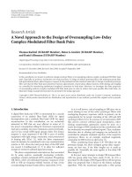
Axle box roller bearings
47 of the Channel tunnel's freight engine, class 92
Class 92 is used for freight traffic in the Euro tunnel
between Great Britain and the Continent. It is a two-
system engine which means it can be operated on di-
rect current (750 V) as well as on alternating current
(25 kV). The engine with six axles (CoCo) draws loads
weighing up to 1,600 t.
The vertical loads of the bogie are accommodated by
two lateral coil springs on the housing of the axle box
bearings. All lateral and longitudinal forces act via the
guiding journals and sleeves which are attached to the
bogie frame and the housing.
The middle axle of each triple axle bogie is designed as
a floating axle box to insure trouble-free operation in
narrow curves. The two outer axles are designed as
standard axles as customary.
Operating data
Vehicle weight 126,000 kg; two bogies each with three
axles; wheel diameter 1,120 mm; top speed v
max
=
140 km/h;
Power P = 5,000 kW at 25 kV AC
4,000 kW at 750 V DC
Bearing selection
Tapered roller bearing units TAROL 150/250 with
pressed cages (JP) are mounted to the outer standard
axles of the vehicles. The bearings are clearance-adjust-
ed, greased and sealed by the manufacturer. Fey lamel-
lar rings provide for sealing on the side facing the
wheel. A gap-type seal prevents rough dirt from pene-
trating the bearings.
The floating axle is accommodated in two cylindrical
roller bearings whose dimensions are 150 x 250 x
80 mm. The extended inner ring allows axial displace-
ment within the bearing of ± 20 mm at a maximum.
Sealing is achieved at the wheel end by means of long-
webbed labyrinths.
Machining tolerances
The inner rings carry circumferential load and have a
tight fit to p6 on the journal.
The housing bores (point load ) are machined accord-
ing to H7.
Bearing clearance
Prior to mounting, the TAROL units of the standard
axle have an axial clearance of 0.665 0.740 mm and
the cylindrical roller bearing units a radial clearance to
C4 in order to compensate for heat expansion.
Lubrication
Both bearing types are lubricated with a lithium soap
base grease. While the lubricant in the TAROL bear-
ings is only changed during the main inspections, the
floating axle bearings must be relubricated in between.
Due to the constant right to left displacement of the
axle lubricant is removed from the bearing area and
therefore has to be replaced regularly.
47: Axle box roller bearings of the Channel tunnel's freight engine, class 92
48 Axle box roller bearings for an underground train
A car has two bogies. Each axle box roller bearings is
cushioned and guided by rubber-metal silent blocks.
These are arranged between the axle box roller bearing
and the frame opening. They are inclined to the verti-
cal and have an angular cross-section.
Operating data
Weight and maximum payload of one car: 34,000 kg.
Number of wheelsets per bogie: 2.
Wheelset weight G
R
: 1,400 kg.
Supplementary factor f
z
: 1.3.
Equivalent dynamic load P = 22.6 kN.
Wheel diameter D
R
= 900 mm.
Top speed v
max
= 80 km/h.
Bearing selection
Two cylindrical roller bearings are mounted per axle
box: One FAG NJ2318E.TVP2.C3.F2.H25 and one
FAG NJP2318ED.TVP2.C3.F2 (dynamic load rating
C = 430 kN).
Machining tolerances
The bearing inner rings carry circumferential load and
are therefore given a tight fit: journal to m6, housing
to H7.
Bearing clearance
The inner rings increase due to the tight fit: the radial
clearance decreases. The outer rings are cooled more
than the inner rings due to the air stream during travel.
This leads to a further reduction in clearance and
therefore a radial clearance C3 was selected.
Lubrication, sealing
A lithium soap base grease is used for lubrication. A
combination of a felt ring and a labrinth was selected
as a means of sealing.
The labyrinth is provided with two axial webs since the
axle boxes are subjected to extreme dirt.
48: Axle box roller bearings for an underground train
49 Axle box roller bearings for a city train
The bogie frame is supported by Chevron springs on
the axle boxes.
Operating data
The equivalent dynamic load P
m
= 37 kN (calculated
from the various load conditions).
Mean wheel diameter 640 mm.
Maximum speed v
max
= 80 km/h.
Bearing selection
The main component of the FAG bearing units
TAROL 90 used here is a double row tapered roller
bearing whose main dimensions are (d x D x B overall
widths cones/cup) 90 x 154 x 106/115 mm.
Bearing clearance
Prior to mounting, the axial clearance of the bearing
unit TAROL 90 is 530 – 630 microns.
Machining tolerances
The bearing cones carry circumferential load and are
therefore given a tight fit: journal n6.
Lubrication, sealing
Lubrication is with a lithium soap base grease. The
TAROL 90 is sealed at both ends with lamellar rings.
The backing ring also has a collar which forms a gap-
type seal with the lid on the wheel side.
49: Axle box roller bearings for a city train
Axle box roller bearings
50 according to AAR standard*) and modified types
The FAG TAROL unit according to AAR standards is
a compact bearing unit with a double row tapered roll-
er bearing as the main component. Seals at both sides
of the bearing, accessories and the grease filling make
the FAG TAROL a ready-to-mount unit. Neither is
the adjustment of the bearing clearance required. The
so-called NFL design (no field lubrication) is consid-
ered standard today. These TAROL units are no longer
relubricated during operation. The bearing grease is
only renewed during a main inspection.
TAROL units do not have to be mounted into a hous-
ing. An adapter is attached between the TAROL unit
and the bogie frame to transmit the loads and support
the bearing cup on the loaded part of the circumfer-
ence.
FAG supply NARROW and WIDE adapters accord-
ing to the AAR standards as well as special adapters de-
signed for the particular cases of application.
AAR has stipulated the admissible loads for the various
sizes of TAROL units.
Components of the FAG tapered roller bearing unit
TAROL
1 Locking plate
2 Cap screw
3 End cap
4 Bearing cup
5 Bearing cone with roller set
6 Spacer
7 Seal wear ring
8 Seal
9 Backing ring
FAG use two types of seals: the rubbing radial shaft seal
(fig. a) corresponds to the design used by AAR. The
non-rubbing lamellar seal ring (fig. b) was developed
by FAG and tested and approved by AAR.
2
1
3
78 5 6
798
4
50: TAROL units
with a double-row tapered roller bearing
*) Association of American Railroads
a: Rubbing radial shaft seal
b: Non-rubbing lamellar seal
FAG also supply TAROL units in metric dimensions.
They (fig. c) have narrower tapered roller bearings and
smaller sealing and retaining components than the
AAR design. The relevant journals are also shorter re-
sulting in lower bending stresses with the same shaft
diameter than in the case of the AAR arrangement.
Higher wheel loads are therefore admissible.
c: TAROL units in metric dimensions and with short journal
(SK design)
51 Kiln trucks for sand lime brick works
Operating conditions
In sand lime brick autoclaves the wheelset bearings of
the kiln trucks are exposed for many hours to hot
steam of approximately 200 °C at 16 to 22 bars. Due
to corrosion hazard the bearing location should be
protected against penetration of the steam which is
strongly alkaline.
Bearings
Sealing requires major attention when designing the
bearing arrangement. The best solution is the use of
pulverized synthetic FAG sealing agent and solid lubri-
cant Arcanol DF. This lubricant is suitable for tempera-
tures ranging between –200 °C and +300 °C and re-
sists almost any chemical even at high temperatures. It
is non-ageing and water repellent. The powder is
packed into the bearing location penetrating into all
cavities of the arrangement and forming a lubricating
film between balls and raceways, balls and cage and
also between outer ring and housing bore. The film in
the housing bore ensures easy bearing displaceability,
even after prolonged operation. This protects the bear-
ing against detrimental axial preload.
In addition to lubrication Arcanol DF also acts as a
sealing agent. It settles in the sealing gaps of the axle
passage and protects the inside of the bearings against
the ingress of alkaline condensate.
The bearings are designed for a truck with two wheel-
sets accommodating a total weight F
r
of 43 kN.
The bearing load for each bearing is relatively low at
F
r
/4 allowing the use of inexpensive FAG
6208.R200.250.S1 deep groove ball bearings.
Considering the high operating temperatures the
bearings have a particularly large radial clearance
(200 250 or 250 350 microns), are heat-treated
according to S1 (200 °C) and are dimensionally stable.
The bearings of the kiln trucks are mounted on the
shaft as far as its shoulder by means of a punching cap
and fastened securely with a shaft end washer and
screw. They have a loose fit in the housing bore of the
FAG series housing SUB6208. Two bolts attach the
housings to the frame of the trucks. Strips inserted
between housing and frame compensate for any differ-
ences in height due to warping of the truck frame.
Machining tolerances
Shaft: bearing seat j6.
Housing: the diameter of bearing seat is between
0.5 mm and 0.8 mm larger than the bearing O.D.
Sealing
Heat-resistant aramide stuffing box packings seal the
bearing area at the axle passage. The cover flange is also
provided with a heat-resistant seal.
51: Kiln trucks for sand lime brick works
Universal quill drive
52 for threephase current locomotives of series 120
All four wheelsets of series 120's threephase current lo-
comotives are driven. The traction motor arranged
transversely to the direction of travel is connected to
the bogie at three points. The torque of the traction
motor acts via pinion and bullgear on a universal quill
drive which is linked to the bullgear and driving wheel
by the articulated lever coupling. The driving wheel
transmits the tractive force to the rails.
Operating data
Top speed: 200 km/h; number of motors: 4; nominal
power per motor: 1,400 kW; motor speed: max.
4,300 min
–1
.
Bearing selection
The bullgear is supported on the universal quill drive
in two tapered roller bearings FAG 534052 (dimen-
sions: 381.03 x 479.475 x 49.213 mm) which are
mounted in O arrangement. Even with a small bearing
distance there is a relatively large spread and as a result
tilting rigidity is high.
The quill drive housing is stationary. The cones, which
carry point load, have a loose fit. The cups carry cir-
cumferential load and have therefore a tight fit in the
rotating bullgear.
The axial clearance of the bearing pair depends on the
machining tolerances of the bearing seats and the oper-
ating conditions. With inner and outer spacer sleeves
bearing adjustment is not necessary when mounting.
Lubrication
During mounting the bearings and the space between
the webs of the outer spacer sleeves are completely
filled with a lithium soap base grease of the NLGI class
2. They are relubricated after every 150,000 km. The
grease is fed through the holes of the sleeve's web.
52: Bullgear bearing arrangement for a universal quill drive
Suspension bearing arrangement
53 for electric goods train locomotive
The torque of the traction motor is transmitted to the
wheelset axle via pinion and bullgear. The traction mo-
tor arranged transversely to the direction of travel is
supported directly on the wheelset axle in two bearing
locations. The reaction torque is taken up by another
support point at the bogie frame.
Operating data
Six driven wheelsets, power per traction motor:
500 kW. Max. speed: 100 km/h.
Bearing selection, dimensioning
For a suspension bearing to have a long service life
(nominal life over 2 million kilometres) roller bearings
with a high load carrying capacity are selected. A me-
dium drive torque and a medium speed are taken as a
basis for dimensioning. The index of dynamic stressing
f
L
should be 3.5 at least. Usually it is well above it.
Two FAG tapered roller bearings are mounted their di-
mensions being 230.188 x 317.5 x 47.625 mm and
231.775 x 336.55 x 65.088 mm. They are abundantly
dimensioned because of the large shaft diameter. High
loads due to vibrations and shocks are accommodated
by special tapered roller bearings with reinforced
pressed cage (reduced number of rollers).
Both tapered roller bearings are mounted in O arrange-
ment with little axial clearance (0.2 0.3 mm). When
the shaft has a maximum load the cups and cones are
tilted by up to 3' against each other. The profile of the
tapered rollers or raceways are modified (slightly
crowned) in order to avoid edge stressing.
Machining tolerances
The cups have circumferential load and an interference
fit on the shaft. The cup or the angle sleeve in the
housing is given a tight fit (perhaps a drive seat).
Lubrication, sealing
The suspension bearings are lubricated with a lithium
soap base grease of penetration class 3 with anti-corro-
sion additives. Baffle plates hold the grease at the bear-
ing (grease storage).
The relubrication interval is about 200,000 to
300,000 km depending on the type of operation.
Labyrinth gap-type seals protect the bearing from con-
taminants.
53: Suspension bearing arrangement for electric goods train locomotive
54 Spur gear transmission for the underground or subway
The drive of modern suburban vehicles should provide
for a high degree of travel comfort, low noise, and be
economical at the same time. These requirements are
fulfilled by a new compact drive package which is
completely supported on springs in the bogie.
Operating data
Two step parallel shaft drive, helical/double helical
gearing. Drive speed (input shaft) n
max
= 5,860 min
–1
,
step-up i = 11.025.
The drive motor is flanged on to the transmission. A
universal joint coupling transmits the torque directly
to the wheelset from the transmission. The gearbox
case, which is split at axis height, is made of high-
strength cast aluminium. This is 25 % lighter than
spheroidal graphite cast iron.
Bearing selection
Input shaft
The rotor of the drive motor is firmly attached to the
input shaft of the transmission. An elastic coupling
which can be subject to bending, avoids constraining
forces in the shaft line which is supported in three
positions by a locating-floating bearing arrangement.
The floating bearing in the motor is a cylindrical roller
bearing FAG NU212E (not illustrated). A second
floating bearing, a cylindrical roller bearing FAG
NJ215E, is at the motor end of the input shaft. The
locating bearing arrangement of the input shaft is an
angular contact ball bearing pair FAG 7215B.UA70 in
X arrangement. Both angular contact ball bearings are
fitted in an angle sleeve made of steel. Therefore differ-
ent heat expansion coefficients of steel and light metal
cannot have a direct effect on the bearings.
The bearings accommodate high speeds with a close
axial guidance at the same time. This means tight fits
for the bearing rings on the shaft and in the bore of the
angle sleeve. The demand for a sufficient axial operat-
ing clearance in addition to the tight fit is met with an-
gular contact ball bearings in universal design. The axial
clearance of the bearing pair prior to mounting is
70 microns.
Intermediate shaft
A spherical roller bearing FAG 22218E is mounted as
the locating bearing of the intermediate shaft. Its outer
ring is in a steel angle sleeve. The spherical roller bear-
ing accommodates chiefly axial forces from the gear-
ing. The floating bearing, a cylindrical roller bearing
FAG NJ2216E.C3, is directly in the light-metal hous-
ing with the outer ring. The very tight fit in the hous-
ing necessitates a bearing with increased radial clear-
ance (C3).
Output shaft
The output shaft whose large spur gear has a double
helical gearing, is axially guided by the spherical roller
bearing of the intermediate shaft. The floating bearing
arrangement with two cylindrical roller bearings FAG
NUZ1848 is therefore sufficient for the output shaft.
The NUZ design with an extended inner ring raceway
allows a large axial displacement of the hollow shaft.
Machining tolerances
Angular contact ball
bearing pair Shaft k5; pair housing K6
Spherical roller bearing Shaft m5; housing K6
Cylindrical roller bearing/
intermediate shaft Shaft m5; housing N6
Cylindrical roller bearing/
output shaft Shaft n5; housing
N6 P6
Lubrication
All the bearings of the transmission are lubricated by
the oil circuit of the gearings.
Antriebs-Hohlwelle
Zwischenwelle
Eingangswelle
54: Spur gear transmission for the underground or subway
Output hollow shaft
Intermediate shaft
Input shaft
55 Bevel gear transmission for city trains
With a so-called two-axled longitudinal drive in under-
ground and metropolitan vehicles the traction motor
(usually direct current motor) is arranged in the bogie
in the direction of travel. A bevel gear transmission is
flanged onto both sides of the motor's face. The drive
unit firmly attached to the bogie frame is elastically
supported by the wheel sets. The drive power is trans-
mitted from the pinion shaft to the hollow ring gear
shaft and then via rubber couplings to the driving
wheel shaft. This drive design leads to good running
behaviour and moderate stressing for the traction mo-
tor, transmission and track superstructure.
Dimensioning, bearing selection
Mean torques and speeds (hourly torque, hourly
speed) are calculated from the tractive force – surface
speed diagram and the time shares for the various run-
ning conditions. By means of the gearing data the
tooth loads of the hypoid bevel gear step are calculated
and, depending on the lever arms, are distributed to
the bearing locations.
A life of 20,000 to 30,000 hours is assumed for bearing
dimensioning. Assuming an average travel speed this
corresponds to 1.2 – 1.3 million kilometers.
To check the static safety of the bearings the maximum
torque (slippage torque) is taken as a basis.
Pinion shaft
A single-row cylindrical roller bearing FAG
NJ2224E.M1A.C3 (120 x 215 x 58 mm) is mounted
as a floating bearing at the pinion end. It accommo-
dates the high radial loads. The machined cage of the
bearing is guided at the outer ring. The bearing has the
increased radial clearance C3 since the bearing rings
have a tight fit on the shaft and in the housing. Two ta-
pered roller bearings FAG 31316 (80 x 170 x 42.5
mm) are used as locating bearings. They are mounted in
pairs in O arrangement. The bearing at the motor end
accommodates the radial loads as well as the axial loads
from the gearing; the other tapered roller bearing only
accommodates the axial loads arising during a change
in direction of rotation. A minimum bearing load is a
requirement in order to avoid harmful sliding motion
(slippage) and premature wear. The cups of the
tapered roller bearings are therefore preloaded with
springs.
Ring gear shaft
There is a tapered roller bearing with the dimensions
210 x 300 x 54.5 mm at each side of the ring gear.
Both bearings are adjusted in X arrangement.
Machining tolerances
Cylindrical roller bearing: Shaft m6, housing M6
Tapered roller bearing/
motor end: Shaft m6, sleeve M6
Tapered roller bearing
with mantle ring: Shaft m6, ring R6 (S7)
Tapered roller bearing
of ring gear shaft: Shaft n6 – p6
housing K6 – M6
The axial clearance of the tapered roller bearing pair
depends on gearing and the operating conditions.
Lubrication
Oil sump lubrication provides the transmission bear-
ings with lubricant. The flinger oil is conveyed via the
ring gear from the oil sump and fed directly to the
transmission bearings via oil collecting bowls and sup-
ply ducts. The special driving conditions for city trains
demand highly doped oils which are resistant to heat
and corrosion.
55: Bevel gear transmission for city trains
56–60Rudder shafts
The rudders of ships make slow intermittent slewing
motions. The maximum slewing angle is about 35° to
both sides. The rudder shaft bearings accommodate
the radial and axial loads arising from the rudder and
the steering engine. The bearings are also subjected to
the vibrations created by the propeller jet. There are
numerous types of rudders the most common of which
are illustrated in figs. a to c.
Rolling bearings are only used for the bearing positions
of the rudders inside ships. They are not suitable for
the bearing positions located outside the ship due to
mounting difficulties and problems with sealing and
lubricating. For such locations, plain bearings made of
stainless steel, bronze, plastic etc. are used and water or
a mixture of grease and water is used for lubrication.
a) Semi-spade rudder b) Spade-type rudder c) Steering nozzle
56 – 57 Spherical roller bearings as rudder shaft bearings
Operating data
Axial load 115 kN (weight of rudder and shaft), radial
load 350 kN (driving force of steering engine and
rudder).
Bearing selection, dimensioning
Due to the heavy loads and unavoidable misalignment
spherical roller bearings are used. They have a high
load carrying capacity and are self-aligning. The rudder
shaft diameter depends on size and speed of the ship as
well as on the type and size of the rudder used. The
bearing bore and the size of the bearing are determined
by the shaft diameter specified. A spherical roller bear-
ing FAG 23052K.MB.R40.90 or FAG 23052K.MB.C2
(radial clearance 150 220 microns) is mounted. Dur-
ing mounting the bearing inner ring is pressed onto
the tapered shaft seat so that the bearing operates
under a light preload. Vibrations can thus be adequate-
ly accommodated. The hydraulic method facilitates
dismounting particularly in the case of bearings with
C2 bearing clearance. For this purpose the shaft must
have oil ducts and the tapered seat a circular groove.
The housings of rudder shaft bearings FAG
RS3052KS.1 or FAG RS3052KW.1 are made of
welded shipbuilding steel plates.
The static safety of a rudder shaft bearing is checked
because of the few slewing motions. An index of static
stressing f
s
between 4 and 5 is suitable for spherical
roller bearings.
Machining tolerances
Shaft taper 1 : 12, housing H7.
Lubrication, sealing
During mounting, the cavities of the spherical roller
bearings and housings are completely filled with lithi-
um soap base grease of consistency number 2 which con-
tains EP additives.
Rudder shaft bearing FAG RS3052KS.1
The bearing is grease lubricated. It sits in the pot-like
housing which is attached to the housing base plate by
sturdy webs. A stuffing box seal is mounted in this base
plate. Its packing runs on a sleeve of seawater-resistant
steel.
Due to the separation between the upper half and the
base any spray water which could penetrate runs along
the side and does not get into the rolling bearing. The
stuffing box can be inspected at any time during oper-
ation and if necessary readjusted. The bottom end of
the bearing is provided with a spring seal. A felt seal
and V ring suffice for sealing at the top end. This bear-
ing arrangement with stuffing box seal is maintenance-
free.
Rudder shaft bearing FAG RS3052KW.1
Bearing and seal are in one and the same housing and
are lubricated with grease. The bearing arrangement
can also be below the waterline. Sealing consists of
three seawater-proof shaft sealing rings with an inter-
mediate grease chamber. An automatic grease pump
holds the latter under permanent pressure.
56: Rudder shaft bearing FAG RS3052KS.1 57: Rudder shaft bearing FAG RS3052KW.1
58–59 Spherical roller thrust bearings as rudder carriers
Spherical roller thrust bearings are used when the top
bearing mainly has to take up the weight of the rudder
and shaft. This is the case for all rudder drives not
loaded by lateral forces, such as for rotary vane steering
gears and four-cylinder engines, which do not operate
spade-type rudders.
The two designs, N and W, for rudder carriers, differ
only in their sealing.
Bearing selection, dimensioning
The shaft diameter is determined according to formu-
lae of the Classification Societies. Thus the bore diam-
eter of the rolling bearing is fixed. Due to the high
axial load carrying capacity a spherical roller thrust
bearing FAG 29284E.MB with the dimensions 420 x
580 x 95 mm is mounted directly on the shaft. The
bearing's index of static stressing f
s
≥ 10.
The welded housings are extraordinarily flat – they
protrude just slightly beyond the deck or mounting
base. This provides advantages especially for larger
steering engines, since the rudder shaft extension can
be kept short due to the low mounting and dismount-
ing height.
Powerful springs under the bearing outer ring provide
a permanent positive contact of rollers and raceways.
The supplementary plain bearing also accommodates
radial forces, if for example a cylinder in a four-cylin-
der steering engine fails.
Machining tolerances
Shaft h7. The housing is relief turned to ensure axial
spring preload via the housing washer.
Lubrication, sealing
During mounting, the cavities of the spherical roller
thrust bearings and housings are completely filled with
lithium soap base grease (consistency number 2 with EP
additives). As with radial spherical roller rudder bear-
ings, there are also two designs (N and W) in the case
of rudder carrier bearings. Only the seal differs:
FAG RS9284N.1 rudder carrier bearings have felt
seals, the rudder carrier bearings FAG RS9284W.1
are sealed with seawater-proof shaft sealing rings.
Both designs have a V-ring seal at the housing cover.
58: Rudder carrier bearing FAG RS9284N.1
59: Rudder carrier bearing FAG RS9284W.1
60 Spade-type rudder
Design
The slewing motion is accommodated by a top bearing
and a bottom bearing. Both bearing locations are
equipped with rolling bearings since they are inside the
ship's hull. The top bearing or rudder carrier is de-
signed as the locating bearing due to the locating ring
between cover and bearing outer ring. The bottom
bearing is the floating bearing. Spherical roller bear-
ings are used at both locations and the bearing
arrangement is therefore statically defined and not
affected by misalignment of housing bores, warping of
the ship's hull and rudder shaft deformation. Both
spherical roller bearings are mounted on adapter
sleeves which are mounted and dismounted by means
of the hydraulic method. The relevant adapter sleeves
(HG design) have connecting holes and grooves for
the pressure oil.
Operating data
Top bearing:
Axial load 380 kN (weight of rudder and shaft).
Radial load 1,700 kN (load from rudder and steering
engine).
Bottom bearing:
Radial load 4,500 kN (load from rudder and steering
engine).
Bearing selection, dimensioning, sealing
Bearing selection is based on the specified shaft diame-
ter and the given loads. Since the bearings only make
slewing motions they are selected according to their
static load carrying capacity. An index of static stressing
f
s
≥ 4 is a must.
The bottom spherical roller bearing, an FAG
230/750K.MB.R60.210 (or 230/750K.MB.C2), is
located on an adapter sleeve FAG H30/750HG. Since
this bearing is permanently below the waterline,
special sealing must be provided for the shaft passage.
The radial sealing rings run on a sleeve made of sea-
water-resistant steel. The lips form a grease chamber
permanently pressurized by an automatic grease pump.
Some of the grease (lithium soap base grease of the con-
sistency number 2 with EP additives) penetrates into
the housing keeping the initial grease packing under
constant pressure.
The seal above the bearing (shaft sealing ring and V
ring) protects it against water which may either run
down the shaft or collect in the rudder trunk.
The top spherical roller bearing, an FAG
23188K.MB.R50.130 (or 23188K.MB.C2), is
mounted on the shaft with an adapter sleeve FAG
H3188HG. The adapter sleeve is fixed axially; below
by the shaft shoulder and above by a split holding ring
which is bolted into a circular groove in the shaft. This
upper bearing also takes up the weight from rudder
and shaft as well as the radial loads. A shaft sealing ring
is fitted at the upper and at the lower shaft diameter
for sealing purposes. There is also a V ring at the upper
shaft passage.
When relubricating with an automatic grease press, the
initial grease filling is kept under pressure and the seal
rings are lubricated at the same time.
Machining tolerances
Rudder shaft h8, cylindricity tolerance IT5/2 (DIN
ISO 1101). Housing H7.
Bearing clearance
The bearings have a particularly small radial clearance:
the lower bearing has 60 to 210 microns or 390 to 570
microns and the upper bearing has 50 to 130 microns
or 230 to 330 microns. During mounting, the bear-
ings are pressed onto the adapter sleeve so far that they
obtain a preload of 20 to 30 microns. With these pre-
loaded bearings vibrations are easily accommodated.
60: Spade-type rudder bearings
61– 62 Ship shaft bearings and stern tube bearings
The propeller shaft of a ship is carried by so-called sup-
port bearings. Since length variations of the shaft are
considerable, particularly with long shafts, the bearings
must have axial freedom. The last part of the shaft sup-
porting the propeller, runs in the so-called stern tube
or tail shaft bearings.
Operating data
Shaft diameter 560 mm; nominal speed of propeller
shaft 105 min
–1
.
Radial load from shaft and coupling 62 kN, no axial
load – the propeller thrust is taken up by the propeller
thrust block (figs. 63 and 64). With a supplementary
factor of 100 % on the radial load (f
z
= 2), shocks or
other dynamic forces are sufficiently taken into consid-
eration when determining the bearing stress.
Bearing selection, dimensioning, sealing
Since the diameter of the ship shaft is specified, the
bearings are overdimensioned for the loads to be accom-
modated. Thus the index of dynamic stressing f
L
ranges
from 4 to 6 and therefore a high nominal life (L
h
) is ob-
tained. With very good cleanliness in the lubricating
gap, endurance strength is reached in the adjusted life cal-
culation (L
hna
) for ship shaft and stern tube bearings.
A spherical roller bearing FAG 239/600BK.MB (di-
mensions 600 x 800 x 150 mm, dynamic load rating C =
3,450 kN) is used as ship shaft bearing. By means of the
hydraulic method the bearing is attached to the shaft
with an adapter sleeve FAG H39/600HG and is located
in a plummer block housing FAG SUC39/600H.1
(fig. 61a). The housing is made of grey cast iron GG-
25 and consists of a unsplit housing body with two
split covers.
The housing's sealing is provided for by the radial shaft
sealing rings in the cover. For small quantities, welded
housings are generally more economical than cast
housings. Fig. 61b is an alternative ship shaft bearing
arrangement made up of a spherical roller bearing
FAG 23048K.MB with adapter sleeve H3048 and a
split plummer block housing S3048KBL.1
(material GG-25).
The ship shaft is surrounded by the stern tube at the
stern. Fig. 62 shows a stern tube bearing arrangement,
both bearings are designed as floating bearings. The tail
bearing is also loaded by propeller weight and wave ac-
tion. Spherical roller bearings are applied here also
whose inner rings, with adapter sleeves, are attached to
the shaft. A special stern tube sealing protects the bear-
ings from seawater.
Machining tolerances
The inner rings carry circumferential load.
Adapter sleeve seat on the shaft h8. Cylindricity toler-
ance IT5/2 (DIN ISO 1101); housing bore H7.
Flanged housings are used for the tail shaft bearings.
Lubrication
The bearings are lubricated with a non-aging oil with
EP additives (viscosity 150 to 300 mm
2
/s at 40°C). The
lower parts of the support bearing housings have view-
ing glasses or oil dip sticks on which the permissible
maximum and minimum oil levels are marked. The
stern tube is filled with oil. The oil pressure is kept a
little higher than that of the surrounding water.
61a: Ship shaft bearing; spherical roller bearing in SUC housing
61b: Ship shaft bearing. Spherical roller bearing in S30.K housing
62: Stern tube or tail shaft bearing arrangement
63–64Ship shaft thrust blocks
The thrust block is located directly behind a ship's en-
gine. It transmits the propeller thrust to the ship.
Apart from a small radial load from the shaft weight
the bearing is loaded by a purely concentric thrust
load. Depending on the direction of rotation of the
propeller, it acts either forward or backward. During
sternway the thrust load is lower and usually occurs
only seldom. Three bearing arrangements are com-
monly used for these requirements:
Fig. 63a illustrates a thrust block arrangement with
two spherical roller thrust bearings for small shaft di-
ameters in a SGA plummer block housing.
Fig. 63b illustrates a thrust block arrangement with
two spherical roller thrust bearings and one radial
spherical roller bearing in an FKA flanged housing.
Both bearing arrangements are used when the axial
load carrying capacity of a radial spherical roller bear-
ing is insufficient when sternway is very frequent. The
spherical roller thrust bearings accommodate the pro-
peller thrust during forward motion and the propeller
pull during sternway. In 63a the thrust bearings accom-
modate the weight also while in 63b the weight of
shaft and propeller is supported by a radial spherical
roller bearing.
Fig. 64 shows ship shaft thrust blocks each with a
spherical roller thrust bearing and a radial spherical
roller bearing:
a: – in SGA housing, b: – in SUB housing
The curvature centres of the outer ring raceways of the
radial and axial bearings coincide. The bearings are
therefore self-aligning and thus misalignment and
bending of the shaft and hull are compensated for. In
these thrust blocks only the propeller thrust is accom-
modated by the spherical roller thrust bearing during
forward motion. The radial spherical roller bearing
transmits the weight of the shaft and the propeller pull
during sternway. The spherical roller thrust bearing
not under stress is preloaded by springs so that it does
not lift during sternway. A constant axial minimum
load is thus ensured.
Machining tolerances
Fig. 63a:
Spherical roller thrust bearing Shaft m6; housing H7
Fig. 63b:
Spherical roller thrust bearing Shaft n6; housing relief
turned
Radial spherical roller bearing Shaft n6; housing F7
Fig. 64a, 64b:
Spherical roller thrust bearing Shaft m6; housing relief
turned
Radial spherical roller bearing Shaft m6; housing H7
Dimensioning of bearings
The diameter of the thrust block shaft is determined
according to the guidelines of the Classification Soci-
eties. Taking the power output into account the nomi-
nal life L
h
[h] and the resulting index of dynamic stress-
ing f
L
are calculated. An f
L
value of 3 – 4 is recom-
mended for the rolling bearings in ship shaft thrust
blocks. Particularly with utmost cleanliness in the lu-
bricating gap, ship shaft thrust blocks reach endurance
strength according to the adjusted life calculation.
Design
Ship shaft thrust blocks are supplied as complete units
FAG BEHT.DRL. The unit includes bearings, housing
with sealing and thrust block shaft with loose flange.
The FAG thrust block housings are supplied either in
split design SGA (figs. 63a and 64a) or in unsplit de-
sign FKA (fig. 63b) or SUB (fig. 64b).
Order example for unit
FAG BEHT:GRL:110.156680, consisting of:
1 Plummer block housing FAG SGA9322.156678
1 Thrust block shaft with loose flange
FAG DRW110 x 610.156678
2 Spherical roller thrust bearings FAG 29322E
1 Locknut FAG KM26
1 Lock washer FAG MB26
Oil lubrication
Operating data
63a: Ship shaft thrust block 63b: Ship shaft thrust block housing 64a, b: Ship shaft thrust block
FAG BEHT.DRL110.1 with FAG FKA94/600.1 FAG BEHT.DRL.200.1 with
2 spherical roller thrust bearings 2 spherical roller thrust bearings 1 spherical roller thrust bearing
1 radial spherical roller bearing 1 radial spherical roller bearing
Diameter of thrust block shaft 110 mm 600/510 mm 200 mm
Power 320 kW 11,400 kW 1,470 kW
Speed 800 min
–1
150 min
–1
500 min
–1
Thrust 55 kN 1,625 kN 170 kN
Forward motion 50 % 50 % 95 %
Sternway 50 % 50 % 5 %
Bearings mounted 2 x FAG 29322E 1 x FAG 239/600B.MB.C3 1 x FAG 23140B.MB
2 x FAG 294/600E.MB 2 x 29340E
Lubrication Oil sump lubrication
1
) Oil sump lubrication
1
) Oil sump lubrication
1
)
Sealing Shaft sealing rings Shaft sealing rings Shaft sealing rings
1
) Non-aging oil with pressure additives (viscosity 150 to 300 mm
2
/s at 40°C)
63a: Complete ship shaft thrust block FAG BEHT.DRL.110.1 (SGA plummer block housing)
63b: Ship shaft thrust block with FKA flanged housing