Modern Developments in X-Ray and Neutron Optics Episode 12 pps
Bạn đang xem bản rút gọn của tài liệu. Xem và tải ngay bản đầy đủ của tài liệu tại đây (3.81 MB, 40 trang )
440 J. Hrd´y and J. Hrd´a
Fig. 26.1. Symmetric Bragg diffraction on a crystal with a lattice plane spacing d
like a mirror. Thus, from the X-ray optics point of view the refraction is not
too interesting.
The situation is different if the crystal surface is not parallel with the
diffracting crystallographic planes. In this case the crystal does not behave
exactly as a mirror any more. The incident and diffracted beams are not sym-
metrical with respect to the surface normal (which is trivial) but they are also
not symmetrical with respect to the normal to the diffracting crystallographic
planes. There are two limiting cases. The asymmetric diffraction corresponds
to the situation when the surface normal lies in the plane of diffraction, i.e.,
the plane determined by the incident beam and the normal to the diffracting
planes. In this case we will call the crystal asymmetric crystal. The diffracted
beam lies in the plane of diffraction; thus the diffraction is still coplanar.
The inclined diffraction occurs when the plane determined by the surface nor-
mal and the normal to the diffracting planes is perpendicular to the plane
of diffraction. Here we will call the crystal inclined crystal. As will be shown
later, the diffraction is noncoplanar. The general asymmetric diffraction is the
combination of the asymmetric and the inclined diffraction.
26.1.1 Asymmetric Diffraction
For the asymmetric diffraction the values ω
0
and Δθ
0
for an incident beam and
the values ω
h
and Δθ
h
for a diffracted beam are not identical and are different
from the values ω
s
and Δθ
s
for the symmetric diffraction. The following set
of relations holds [4]:
ω
0
= ω
s
b
−1/2
,
ω
s
=(2r
e
λ
2
P |F
hr
|e
−M
)/πV sin 2θ
B
,
Δθ
0
=(1/2)(1 + 1/b)Δθ
s
,
Δθ
s
= r
e
λ
2
F
0r
/πV sin 2θ
B
,
ω
h
= ω
s
(b)
1/2
, (26.2)
Δθ
h
=(1/2)(1 + b)Δθ
s
,
θ
0
= θ
B
+Δθ
0
,
θ
h
= θ
B
+Δθ
h
,
b =sin(θ
B
− α)/ sin(θ
B
+ α).
26 Diffractive-Refractive Optics 441
Here V is the unit-cell volume, r
e
= e
2
/mc
2
(classical electron radius), F
hr
is
the real part of the structure factor F
h
(h stands here for M¨uller indices hkl),
P is the polarization factor, and e
−M
is the temperature factor. The index
s stands for the symmetrical diffraction. The angle α is the angle between
the diffracting planes and the surface and is taken as positive for grazing
incidence. The asymmetry index, b, is defined according to Matsushita and
Hashizume [4]. The typical values of Δθ
s
and ω
s
are from fractions to tens of
angular seconds. The angle θ
B
is the Bragg angle calculated from the Bragg
law (1). For the cross sections CS
0
And CS
h
of the incident and the diffracted
beams the following holds:
CS
h
= CS
0
/b (26.3)
and together with (26.2),
ω
h
CS
h
= ω
0
CS
0
. (26.4)
The consequence of the above relations may be demonstrated with the help
of the DuMond graph (Fig. 26.2a). The real situation is shown in Fig. 26.2b.
Let us suppose that a parallel and polychromatic beam is impinging on an
asymmetrically cut (= asymmetric) crystal with some angle, θ, between the
beam and the lattice planes. The deviation from a mirror-like behavior may be
described by the quantities δ and Δδ. It obviously holds (for one harmonic):
δ(α)=Δθ
0
− Δθ
h
,
Δδ(α)=|ω
0
− ω
h
|.
(26.5)
The deviation δ and the spread Δδ, which may be changed by changing α
resembles the refraction of light on a prism. The only difference is that the
Fig. 26.2. (a) DuMond diagram of an asymmetric Bragg diffraction showing that as
compared with a symmetric diffraction the diffracted beam is deviated and spread.
Figure 26.2b shows the asymmetric Bragg diffraction of a polychromatic pencil beam
in real space
442 J. Hrd´y and J. Hrd´a
prism accepts a broad range of wavelengths, whereas the crystal accepts only
narrow wavelength interval ω
0
(dλ/dθ) and thus the interval Δδ is narrow.
Nevertheless, it exhibits a wavelength dispersion, as in the case of a prism.
One may deduce that this refraction effect (δ, Δδ) may play an important role
when the surface of crystal is curved (not bent), as in the case of refraction
lenses in classical optics. The asymmetric diffraction with flat crystals is used
to either compress or to extend the diffracted beam. This will be treated
elsewhere in this book. (see the Chap. 29)
26.1.2 Inclined Diffraction
The inclined Bragg diffraction is a noncoplanar diffraction. The behavior of
the diffracted beam may be seen in Fig. 26.3a, which shows the wave vectors
and the dispersion surfaces in reciprocal space [5,6]. The points P
0,1
and P
0,2
are the origins of the impinging vectors, directed into the origin, O,ofthe
reciprocal space, points P
h,1
and P
h,2
are the origins of diffracted vectors for
symmetric Bragg diffraction (β =0).ThepointsP
h,1,β
and P
h,2,β
are the
origins of diffracted vectors for the inclined diffraction. The indices 1 and
2 represent the limiting beams within the diffraction region, ω. It is seen
that if the impinging monochromatic and parallel beam is scanned through
the diffraction region, ω
0
(ω
0
= ω
s
), then the diffracted beam is deviated
from the plane of diffraction, and this deviation grows during the scan. The
consequence of this is demonstrated in Fig. 26.3b. It shows that if a parallel
and polychromatic beam impinges on an inclined crystal with an inclination
angle β, then the diffracted beam is deviated from the plane of diffraction in
a sagittal direction (perpendicular to the plane of diffraction) and the beam
Fig. 26.3. Wave vectors in reciprocal space for an inclined diffraction (a). Inclined
diffraction in a real space (b)
26 Diffractive-Refractive Optics 443
is sagittally spread. The deviation, δ, of the central beam from the plane of
diffraction is
δ = K tan β (26.6)
where
K =(2r
e
F
0
/πV )d
hkl
λ. (26.7)
For Si crystals K =1.256 × 10
−3
d
hkl
(nm) λ (nm). The inclined crystal
monochromators based on the inclined diffraction are used to decrease the
impinging radiation power density of synchrotron radiation. Here the devia-
tion and the spread of the diffracted beam is the manifestation of refraction.
As in the asymmetric diffraction, here the beam spread is also limited by
the wavelength acceptance of a crystal for a given incidence angle. From the
above it is clear that, as in the asymmetric case, interesting applications may
be expected if the diffracting surface is machined into a suitable shape.
The refraction effect exists also in general asymmetric diffraction (the com-
bination of asymmetric and inclined diffraction) and in Laue diffraction. These
will be discussed later.
X-ray refractive lenses are now commonly known and are successfully used
for focusing synchrotron radiation [7]. The aim of our work was to study the
diffraction on crystals with curved diffracting surface and to investigate the
possible applications of effects based on refraction described earlier.
The idea of a crystal monochromator with a curved (not bent) diffracting
surface is not new. The Johansson spectrometer [8,9] is a Bragg crystal with
a circular profile machined into the working surface of the crystal. The crystal
is then bent. Such a crystal focuses the monochromatic radiation on the Row-
land circle. Spieker [10], designed a channel-cut crystal monochromator with
profiled working surfaces such that the position of the exit beam remains fixed
when tuning the wavelength. These two methods are based only on geometry;
the refraction effect is completely neglected.
26.2 Bragg Diffraction on a Transverse Groove
(Meridional Focusing)
From what was explained in section 26.1.1 and from Fig. 26.2b it may
be deduced that the radiation diffracted on properly designed transverse
groove may be meridionally focused. This is demonstrated in Fig. 26.4a. The
diffracted beam 1 is deviated to the right due to the asymmetric diffraction and
it is spread. The beam 3 is also spread and is deviated in the opposite direction,
i.e., to the left. The beam 2, which is diffracted from the bottom of the groove
where the diffraction is symmetrical, is neither deviated nor spread. The prob-
lem is to find the function g(x) describing the shape of the groove, such that
the centers of all diffracted beams (i.e., centers of the fans) will be concentrated
into one point, the focus. Substituting (26.2) into (26.5) we obtain
δ =2Δθ
s
tan θ
B
tan α/(tan
2
θ
B
− tan
2
α). (26.8)
444 J. Hrd´y and J. Hrd´a
Fig. 26.4. Bragg diffraction on a transverse groove machined into a symmetric
crystal (a). The diffracted beam is convergent. Figure 26.4b shows image of an
X-ray beam diffracted on a crystal with a transverse groove
Let the profile of the groove be described by a function y = g(x)(see
Fig. 26.4a). Let us suppose that the impinging radiation is parallel. In order
that the beam impinging on the surface of the groove at a certain point,
A(x, y), be diffracted to the focus, the deviation, δ, must be [11]
δ =[−x sin(θ
B
+Δθ
0
)+y cos(θ
B
+Δθ
0
)]/f, (26.9)
where f is the focal distance.
Taking into account that tan α = −g
(x)(g
=dg/dx) and neglecting Δθ
0
in (26.9), then (26.8) and (26.9) gives the differential equation [11]
[x sin θ
B
− g(x)cosθ
B
]/f =2Δθ
s
tan θ
B
g
(x)/{tan
2
θ
B
− [g
(x)]
2
}, (26.10)
which describes approximately the shape of the transverse groove. In [12] this
equation was further modified to include the finite divergence of the impinging
radiation.
The shape of the groove obviously depends on the wavelength, λ,the
focusing distance, f, and the source–crystal distance, S.Inorderthatsuch
a focusing monochromator could be used for a broad wavelength region, it is
necessary to produce either several parallel grooves for various λs or only one
groove whose shape changes along the groove axis. The focusing conditions
could be then adjusted by a translation of the crystal.
We have demonstrated this kind of focusing by an experiment performed
in ESRF at the BM5 beamline [12]. The transverse groove, machined into
a Si(111) crystal, was calculated for λ =0.15 nm,S=40m,andf =2m.
Figure 26.4b shows the image of the diffracted radiation at the distance of 2 m
from the crystal. The figure shows, in the upper and lower parts, the image
of the radiation diffracted from the flat part of the crystal and between them
26 Diffractive-Refractive Optics 445
there is the image of the radiation which is diffracted on the groove and is
concentrated into a narrow bright line. The width of the groove was about
2.5 mm.
Because of the spread, Δδ, of the diffracted beam the focus cannot be
sharp. Even without any refraction effect the diffracted radiation would be
concentrated at the right side of the groove because of the asymmetric diffrac-
tion. It makes sense to compare the peak intensity in the focal plane after
diffraction from the groove and from a flat asymmetric crystal with the
asymmetry corresponding to the right side of the groove. The ray-tracing
simulation of the experiment showed that the groove would give about 3.3
times higher intensity in the peak at the focal plane than an asymmetric
concentrator.
26.3 Harmonics Free Channel-Cut Crystal
Monochromator with Profiled Surface
Another application of diffraction on the meridionally profiled (curved) sur-
face may be a channel-cut crystal monochromator which suppresses higher
harmonics in the broad region of the Bragg angles. Let us suppose that the
first diffracting surface (the first wall of the channel) is flat and symmetrically
cut (its surface is parallel with diffracting crystallographic planes). If the sec-
ond wall is also flat but asymmetrically cut, then Δθ
h
and ω
h
for the first
wall (Δθ
h
=Δθ
s
and ω
h
= ω
s
)isnotequaltoΔθ
0
and ω
0
for the second
wall, and only a part (or none) of the radiation diffracted from the first wall
is diffracted from the second wall: i.e., diffraction is detuned. This depends
on the degree of overlap of the corresponding Darwin–Prins (DP) curves. The
values Δω and ω decrease with the order of diffraction k. This means that for
a certain asymmetry of the second wall, the DP curves for higher harmonics
do not overlap any more but the overlapping of DP curves for the fundamen-
tal harmonic is still sufficient. The radiation diffracted from the channel-cut
crystal is then practically free of higher harmonics. This way of obtaining
harmonics rejection, which is valid for one λ and its close neighborhood was
suggested by Matsushita and Hashizume [4]. The mathematical description of
this situation is following:
(P |F
(k)
hr
|e
−M(k)
)/|F
0r
| =(
1
/
2
)|1/b
1/2
− 1| (26.11)
where b corresponds to the second surface and k (>1) stands for the order of
diffraction.
As the left part of (26.11) is independent of θ, b must also be independent
of θ. This implies that α must change with θ, which means that the second
wall must be curved in order that the channel-cut crystal monochromator
rejects higher harmonics in the whole region of θ or λ [13].
446 J. Hrd´y and J. Hrd´a
Fig. 26.5. Harmonics-free channel-cut crystal monochromator: the derivation of the
shape of the second diffracting surface (a). The second diffracting surface may be
convex (b)orconcave(c)
The equation for b (see (26.2)) may by rewritten as follows:
tan α =[(1−b)/(1 + b)] tan θ = B tan θ. (26.12)
Let us introduce the axes of the coordinates with the origin on the first
wall, such that the X-ray beam is impinging at the origin on the first wall
(Fig. 26.5a). The axis of rotation of the monochromator also passes through
the origin. Let the profile of the second wall be described by the function f(x).
Then (26.12) may be rewritten in the following form:
df(x)/dx = Bf(x)/x. (26.13)
The angle α is here taken as negative. Thus b>1andB<0. The solution of
this differential equation is
f(x)=Cx
B
(26.14)
where B is negative and the second wall of the crystal is convex.
It is obvious, that by a similar consideration as above, the second wall of
the channel-cut crystal may be cut so that the angle, α, is positive [14]. In this
case the DP acceptance curve for the diffraction on the second wall is shifted
toward higher angles, θ. The condition when the DP curves just touch each
other is the same as in the previous case, however, |1/b
1/2
− 1| =1/b
1/2
− 1,
because b<1. This leads to (26.14) where B is positive and the second wall is
concave. Both kinds of channel-cut crystal monochromators are schematically
shown in Fig. 26.5b, c.
It is obvious that the monochromator with a convex wall concentrates the
diffracted beam but slightly increases its divergence, as follows from para-
graph 26.2 (or section 26.2 or 26.2). The monochromator with concave beam
creates a broad beam and slightly decreases its divergence or may even cre-
ate a slightly convergent beam if the impinging beam is almost parallel, as
it is in the case of synchrotron radiation. This has been discussed in detail
in [14]. Obviously, the harmonics rejection here is the consequence of the
26 Diffractive-Refractive Optics 447
dependence of refraction on α and the order of diffraction. The harmonics-
free channel-cut crystal monochromator discussed above has not yet been
tested experimentally.
The width of Darwin–Prins function for the π polarization is cos 2θ times
smaller than for the σ polarization component. As was shown by Hart and
Rodrigues [15], a double crystal monochromator in a nondispersive (+, −)set-
ting which is detuned may reject the π polarization component similarly as
it rejects higher harmonics [16, 17]. Only the degree of detuning is different.
It is obvious that there should exist a channel-cut crystal monochromator
with a suitably curved diffracting surface such that it rejects π polariza-
tion components for a broad region of θ. This will be treated in detail
elsewhere [18].
26.4 Bragg Diffraction on a Longitudinal Groove
(Sagittal Focusing)
In section 26.1.2 it was shown that in the case of an inclined diffraction the
diffracted beam is deviated sagittally (perpendicularly to the plane of diffrac-
tion). Let us suppose that a longitudinal groove is produced in the diffracting
surface of a crystal, as shown in Fig. 26.6a. The opposite walls of the groove
deviate the beam in opposite directions. It is clear, that a properly designed
shape of the groove may sagittally concentrate the diffracted beam at cer-
tain distance, f, from the crystal. The geometry of the diffraction is shown in
Fig. 26.6b. For the determination of the shape of the groove we will suppose
Fig. 26.6. Bragg diffraction on a crystal with a longitudinal groove (a ). The diffrac-
ted beam is convergent. Geometry of the sagittal focusing due to the longitudinal
groove (top view)(b)
448 J. Hrd´y and J. Hrd´a
that the distance of the grooved crystal monochromator from a point source
is S and the focal length is f. Let the shape of the groove be described by a
function y(x). For the groove to act as a lens, it is necessary that the beam
impinging on the crystal (groove) at a distance x from the longitudinal axis
of the groove, be deviated by an angle
δ
∼
=
tan δ
∼
=
[x(S + f )/S]/f = xR/f. (26.15)
Equation (26.6) may be rewritten in the following way:
tan δ = K(dy/dx). (26.16)
Equations (26.15) and (26.16) give a differential equation with the solution [6]
y =(R/2Kf)x
2
+ constant. (26.17)
The meaning of the above result is that the longitudinal parabolic groove
focuses the radiation and thus acts as a sagittally focusing lens. For syn-
chrotron radiation two crystals in a parallel, nondispersive (+, −) orientation
are commonly used. The parabolic longitudinal groove may be then produced
in both crystals. If only one crystal or more crystals in a nondispersive posi-
tion are used, then the advantage of the sagittal focusing is deteriorated by
two effects. The first one is shown in Fig. 26.7a. The vertical size of the beam
increases after each diffraction. This depends on the depth of the groove. The
second effect is the sagittal spread of the deviated beam which prevents the
focus from being sharp.
Both effects mentioned above (aberrations) may be canceled by using a
dispersive arrangement of crystals. From Fig. 26.7b it is clearly seen that
the vertical broadening which appears after diffraction from first two crys-
tals is completely canceled after diffraction on the following two crystals. The
dispersion arrangement also cancels the sagittal spread seen in Fig. 26.3b.
Fig. 26.7. A longitudinal groove broadens the diffracted beam vertically (a).
Dispersive four crystal arrangement with longitudinal grooves cancels the vertical
broadening of a diffracted beam originating from the first two crystals (b)
26 Diffractive-Refractive Optics 449
The nature of the sagittal spread is shown in Fig. 26.3a. When the imping-
ing (monochromatic) beam spans the diffraction region, ω
0
, from smaller to
higher θ, then the sagittal deviation grows. For example the beam correspond-
ing to a smaller θ at the beginning of the diffraction region leavesthecrystal
with minimal sagittal deviation. Let us suppose that there is another crys-
tal adjusted in dispersion position with respect to the first crystal. This beam
impinges on the second crystal at the end of the diffraction region correspond-
ingtoahigherθ and the sagittal deviation is maximal. The resulting deviation
after diffraction on both crystals is 2δ for any beam impinging on the crys-
tals within the region ω
0
. The angle δ is the average deviation as shown in
Fig. 26.3b. This holds for any θ within the region ω.Thisveryimportantresult
shows that the (−, +, +, − ) arrangement, shown in Fig. 26.7b, is ideal [19].
The second and the third crystals cancel the aberrations discussed above and
the first and fourth crystals keep the direction of impinging and exit beams
the same, which is important for synchrotron radiation. The position of the
exit beam remains independent of θ. Moreover, the dispersion arrangement is
the high resolution one. This arrangement should provide practically point-to-
point focusing, which means that we may expect a sharp focus. The practical
expressions important for the design of the parabolic groove are following
y(mm) = a(mm
−1
)(x(mm))
2
, (26.18)
a =(S + f)/2NKfS, (26.19)
where f (mm) is the focusing distance, S (mm) is the monochromator-source
distance and N is the number of diffraction events on the grooves. For the
four crystal arrangement shown in Fig. 26.7b, N = 4 provided that the beam
is diffracted only once on each crystal. The focusing distance f may be
determined from
f = S/(2aNKS − 1). (26.20)
The parabolic groove may also be cut into an asymmetrically cut crystal.
This is treated in detail by Hrd´y [20]. It was shown there that for this case
all the above formulae may be used. Only K must be replaced by
K
= K [(2 + b +1/b)/4cosα]. (26.21)
The difference between the function of the symmetrically and asymmetri-
cally cut grooved crystals may be seen in Fig. 26.8. It shows a dependence of
the focusing distance, f, on the Bragg angle θ for a four-crystal (+, −, −, +)
monochromator with the same crystals and grooves. Crystals cut symmetri-
cally is compared with asymmetric crystals with α =12.38
◦
. The monochro-
mator with the asymmetric crystals gives a shorter focusing distance. In the
angular region around θ =22
◦
the focusing distance is almost constant and
for the highly asymmetric case, close to θ = α, the focusing distance is very
small. The above expressions enable one to be able to design the crystals, the
grooves and the asymmetry angle to meet the experimental requirements.
450 J. Hrd´y and J. Hrd´a
Fig. 26.8. The dependence of the sagittal focusing distance, f, on a Bragg angle, θ,
for a symmetric (α = 0) and an asymmetric Bragg diffraction
As was shown earlier, the ideal shape of the longitudinal groove is a
parabolic groove. Our first experiment [19], which successfully demonstrated
the sagittal focusing, used two channel-cut crystals with the parabolic grooves
cut into each diffracting surface (Fig. 26.9a). To produce the grooves a precise
diamond tool with a parabolic profile was ordered. As the tool was expensive,
we later chose another approach [21]. We drilled a circular hole into a Si sin-
gle crystal either parallel to diffracting planes (to simulate the symmetrical
diffraction) or under some angle, α, to simulate an asymmetric diffraction.
The X-ray beam is then diffracted twice inside the hole. The diameter D of
the hole is given by
D =1/a, (26.22)
where a is the parameter of the parabola (26.18). The circular hole is then
a good approximation of the parabolic groove if the sagittal beam size is
small. One such crystal with three holes of different diameters, for three dif-
ferent λs, drilled in a Si crystal and used for an experiment at APS is shown
in Fig. 26.9b. The more sophisticated design of the asymmetric channel-cut
crystal with circular grooves is shown in Fig. 26.9c. This crystal monochro-
mator was designed such that it accepts a relatively large sagittal extent of a
synchrotron radiation beam (BM5 beamline at ESRF) and creates a focus at
the distance of 20 m. Finally we produced asymmetric crystals with parabolic
holes (Fig. 26.9d) but the experiment has not been done so far. The crystals
with a parabolic hole seem to be the ideal solution because it is compact and
26 Diffractive-Refractive Optics 451
Fig. 26.9. Various realizations of sagittally focusing monochromator crystals. Two
such crystals in a dispersive arrangement were used. A channel-cut crystal with
parabolic grooves is shown in Fig. 26.9a. Figure 26.9b shows a symmetric crystal
with three cylindrical holes for three different wavelengths. Diffraction occurs twice
inside the hole. The more sophisticated asymmetric crystal with cylindrical holes of
large diameter, D, is shown in Fig. 26.9c. An asymmetric crystal with a parabolic
hole is shown in Fig. 26.9d
practically aberration free even though the crystal production is rather labo-
rious. A disadvantage of the crystal with holes is that they cannot be detuned
to reject harmonics. In fact, however, this is not a problem. Higher harmonics
are practically not focused because of low refraction. It means that in the
focus the fundamental harmonic is concentrated whereas higher harmonics
are located mostly out of the focus.
To simulate the focusing described above, a ray-tracing program had to be
developed which included the refraction effect during Bragg diffraction [22].
This program, although being based on some simplifications like rectangular
shape of DP curves, proved to be very useful when discussing the influence of
misalignments and shape imperfections of crystals. Later on, another program
based on precise dynamical theory was developed by another group [23] and
was used to study the aberration of the (−, +, +, −) arrangement with four
longitudinal parabolic grooves [24]. This showed that the system is practically
aberration free. In spite of this, the size of the focus in our experiments was
always somewhat larger than the theoretical one. This is due to the quality of
452 J. Hrd´y and J. Hrd´a
the groove. First, the circular shape introduces some aberration. Second, it is
difficult to produce an exact shape into the Si crystal, because after machining
the surface must be etched and mechano-chemically polished. This is done by
hand, and to keep the exact groove profile with high precision is very difficult.
The focusing distance in the (−, +, +, −) arrangement depends on the
parameter a of the parabola and the wavelength, λ. For example in the first
experiment at NSLS [19] the width of the groove in the Si channel-cut crystals
was 2 mm, the depth was slightly more than 1 mm and the energy E =15keV.
The focusing distance was 4.5 m and the beam, whose size at the focusing dis-
tance would be 2.7 mm without focusing, was squeezed to a spot of 0.29 mm
despite the relatively bad quality of the groove surface. The experiment at the
5ID beamline at APS [25] with a hole diameters of 7.2 mm for 8.048 keV and
4.4 mm for 13 keV, the focusing distance of 20 m, the crystals–source distance
of 55 m, and Si(111) symmetrical diffraction gave the focus size of 417 μm,
which is 110 μm larger than the size of the demagnified image of the source.
Finally, in the experiment performed at the BM5 beamline at ESRF [26], we
used an asymmetric Si(111) channel-cut crystal of a very special design with
hole diameters of 22 mm such that the size of the crystals could be reason-
ably small (Fig. 26.9c). The source-to-crystals distance was 40 m, the focusing
distance was about 20 m, and the energy about 8 keV. The crystals accepted
6 mm of the horizontal size of the beam and created the focus of the size of
0.4 mm. Figure 26.10 shows the focused beam. The focal spot is clearly seen
against the broad background of higher harmonics which are practically not
focused because of low refraction. The width of the unfocused radiation at the
focusing distance was 8.8 mm. The size of the image of the demagnified source
at the focal distance was 0.12 mm. In the last two experiments mentioned, the
diffracting surfaces were mechano-chemically polished.
It is seen that for the long focusing distances the size of the demagnified
image of the source is also large. There are three ways by which one can
decrease the focusing distances. The first one is to use strongly asymmetric
diffraction as is shown in Fig. 26.8. This is possible only for a narrow wave-
length region. The second way is to use a multiple diffraction arrangement,
Fig. 26.10. Sagittally focused first harmonics on the background of higher harmon-
ics which are practically not focused. The image was taken at 20 m from the crystal
shown in Fig. 26.9c. The width of the image of the higher harmonics is about 9 mm
26 Diffractive-Refractive Optics 453
Fig. 26.11. Multiple crystal arrangements to decrease the focusing distance
Fig. 26.12. “Toothed” profile of a longitudinal groove to reduce the size of a crystal
and the vertical broadening of a diffracted beam
for example (−, +, −, +, +, −, +, −) (Fig. 26.11a). When using channel-cut
crystals with four reflections on each crystal, because the vertical size of the
beam grows after each reflection, the required size of the crystal might be
larger than is technically feasible. To avoid this, several (even number) of
channel cut crystals may be arranged in a dispersive position to create the
arrangement (−, +, +, −, −, +, +, −, ) (Fig. 26.11b). The alignment of such
a crystal arrangement would obviously be complicated. The third possibility
is to use a very narrow groove (large a) which leads to a very low angular
acceptance. From the above it is seen that the microfocusing by this method
is principally possible but with the present technology of growing Si crystals
and preparing their perfect curved surfaces it is difficult. By this method,
however, it is very easy to concentrate the diffracted radiation sagittally at
long focusing distances, because a large change of β results in a small change
of the sagittal deviation, δ. It means that the precision of the parabolic groove
(or the hole) does not have to be extremely high. As compared with the clas-
sical method, i.e., two crystals with the second crystal sagittally bent [27],
the diffractive–refractive optics is compact, first two reflecting surfaces may
be easily cooled as a whole when using a channel-cut crystals or crystals with
holes. However, the tunability range is smaller and the acceptance is also
smaller with presently available Si crystal sizes. On the other hand, the focus
should be sharper because of the negligible aberration. Theoretically, the hor-
izontal (sagittal) acceptance may be large but if the parabola describing the
shape of the groove is narrow (large a) then the height of the crystal needed
may be too large. This problem may be solved by a more complicated profile
of the groove, as shown in Fig. 26.12. The tunability range may be increased
454 J. Hrd´y and J. Hrd´a
by producing several holes or grooves with different sizes and different asym-
metry angles in each crystal. Switching between different wavelength regions
may be accompanied by switching between different grooves or holes. Another
possibility may be to produce grooves or holes with variable parameters along
their axes (e.g., a conical groove or hole). The change of wavelength may then
be accomplished simply by shifting the crystals along the axis of the groove.
So far focusing only in one direction has been described. As suggested
in [11] it should in principle be possible in a (−, +, +, −) arrangement to
produce longitudinal grooves, for example, in the second and the third crystals
and transverse grooves in the fourth crystal. This should concentrate the beam
in both directions. Another possibility may be to produce a properly designed
depression in the surface of one crystal. Neither of the methods has been
tested experimentally.
26.5 Laue Diffraction on a Profiled Surface
(Sagittal Focusing)
A logical continuation of the work described above is the study of the possible
application of the refraction effect occurring during Laue diffraction. Recently,
the sagittal deviation of a beam diffracted from a sagittally inclined surface
was studied for Laue asymmetric diffraction [28, 29]. In this work the sagittal
deviation of the beam diffracted from a flat asymmetric Laue crystal with
a sagittally inclined wedge was observed experimentally. The simple theory
presented in [28] gives the formula for the sagittal deviation, δ,ofthebeam
(Fig. 26.13):
δ =(|PN|λ)tanβ =(|LP| [cos θ/cos(θ + α)]λ)tanβ, (26.23)
where
|LP| =[r
e
λ/(2πV cos θ
B
)][F
0r
− ρ|F
hr
|exp(−M)]. (26.24)
Fig. 26.13. Laue diffraction: diffracted and forward diffracted beam; both are sagit-
taly deviated
26 Diffractive-Refractive Optics 455
Here r
e
is again the classical electron radius, V is the volume of the unit
cell, θ
B
is the Bragg angle, ρ is the polarization factor, and F
0r
and F
hr
are
the real parts of the structure factors of the corresponding reflections (see, for
example, [2]). The angle α is the deviation of the entrance surface from that in
the symmetrical Laue case and β is the inclination angle. Here, it is assumed
that in the vicinity of the Laue point the Ewald spheres may be replaced by
planes.
As was suggested in [28] the effect of sagittal deviation discussed above
may be utilized to sagittally focus the synchrotron radiation by a Laue crystal
with a parabolic profile of one or both diffracting surfaces. Equation (26.23)
is analogous to the formula (26.6). As in the Bragg case, this leads directly
to a parabolic shape y = ax
2
of the diffracting surface. The parabolic surface
may be approximated by a circular hole with the diameter D,whereD =1/a.
Obviously, (26.23) could be applied to the design of a sagittally focusing Laue
crystal with the profiled diffracting surface (parabolic or circular) if K from
(26.19) is replaced by (|LP|[cos θ/cos(θ + α)]λ). This is valid only if the exit
surface is profiled and for the diffracted, not a forward diffracted, beam (see
Fig. 26.13). The sagittal deviation of the forward diffracted beam is much
smaller. The equally profiled entrance surface influences the sagittal deviation
of the diffracted beam much less if the geometry is as shown in Fig. 26.13.
This is discussed in detail in [30]. To understand the meaning of |LP| and
|PN| in reciprocal space see [28].
For the experiment we used an asymmetric Si Laue crystal shown in
Fig. 26.14. The diffracting part is the space between two cylindrical holes
with the diameter D =1/a = 8 mm. (The circle with the diameter D =1/a
is a good approximation of parabola y = ax
2
for small x). The walls of the
holes represent a sagittal tilt. The (111) diffracting crystallographic planes
are deviated from the holes axes by 7.95
◦
,sothatα =82.05
◦
.Boththe
Fig. 26.14. Asymmetric Laue crystal with profiled entrance and exit surface. The
working area is the space between the two circular holes
456 J. Hrd´y and J. Hrd´a
entrance and the exit diffraction surfaces were mechano-chemically polished.
The experiment was performed at the BM05 beamline at ESRF (MI751).
After the Laue crystal we used a Bragg Si(111) symmetric crystal to redi-
rect the Laue diffracted beam into a horizontal direction. To limit the presence
of higher harmonics in the beam and to avoid the problem with energy deter-
mination, we used a primary monochromator which was set to 15.35 KeV
(θ =7.4
◦
) and was detuned. There were two beams which were diffracted
from the crystal. The forward diffracted beam was not used, because the
refraction effect is small (the refraction effect is stronger for beams forming
a smaller angle with a surface). The diffracted beam which was used formed
the angle of 0.55
◦
with the crystal exit surface and deviated from the hori-
zontal plane by the angle 2θ =14.8
◦
. Even if we had used a white beam, this
combination of the Laue and Bragg crystals would have allowed us to reject
higher harmonics, the angular distributions of harmonics for Bragg and Laue
diffraction being different. The beam size was delimited by a slit 3 × 3mm
located before the Laue crystal. The crystals–source distance was 35 m.
Figure 26.15a shows the image of the diffracted beam just after the Bragg
crystal. The horizontal (sagittal) dimension of the spot, i.e., the distance
between the border beams A and B is 3.22 mm. The shape of the spot
is a narrow “smile” because of the circular profile of the diffracting sur-
faces and the asymmetric diffraction. The image taken at 20 m from the
crystal (Fig. 26.15b) is more complicated: it has the shape of a horseshoe.
The border beams A and B are sagitally deviated such that their distance
is 1.720 mm. Without focusing, the distance between both beams would be
3.22 ×(55/35) = 5 mm (the crystals–source distance is 35 m and the detector–
source distance is 55 m). Together with the sagittal deviation, the beams are
also sagittaly spread (see the dimensions a and b). This situation is analogous
Fig. 26.15. The image of the Laue diffracted beam from the crystal shown in
Fig. 26.14. Figure 26.15a shows the image taken close to the crystal, Fig. 26.15b is
the image taken 20 m from the crystal
26 Diffractive-Refractive Optics 457
to the Bragg diffractive–refractive optics if only one crystal is used. The higher
the deviation is, the higher is the spread. The consequence of this is that one
crystal, or more crystals in a nondispersive arrangement, cannot create a sharp
focus. In the Bragg case only two or more crystals in the dispersive arrange-
ment completely cancel the sagittal spread so that the focus may be sharp [19].
We suppose that the same holds for the Laue diffractive–refractive optics.
From the distances between the beams A and B near the crystals and at
20 m from the crystals we can deduce that the diffracted radiation is conver-
gent and the focusing distance is about +43 m, which is, however, different
from the theoretical prediction. This indicates that further theoretical and
experimental work is necessary.
The experiment described above shows that the idea of diffractive–
refractive optics developed for Bragg diffraction in the past can be extended
also to Laue diffraction. It was shown that the asymmetric Laue crystal with
profiled diffracting surfaces may concentrate the diffracted beam and thus
increase the intensity in the diffraction spot.
To improve the quality of the focus, i.e., to cancel the sagittal and vertical
spreads, two Laue crystals with profiled surfaces in dispersive setting should
be used (see the analogy with the Bragg diffractive–refractive optics). The
experimental test of this idea is under preparation.
Such sagittal focusing might in some cases serve as an alternative to
the sagittal focusing by a sagittally bent asymmetric Laue monochromator
described by Zhong et al. [31, 32].
26.6 Conclusion
Practically all existing X-ray crystal monochromators are produced with a flat
diffracting surface. Such crystals may be bent to focus diffracted radiation.
In this chapter it is shown that if the diffracting surface is machined into a
suitable shape, the diffracted monochromatic beam may gain some additional
useful properties. It may be sagittally or meridionally focused or either higher
harmonics or the π polarization component may be filtered over a broad range
of Bragg angles. It is shown that these properties are the result of refraction.
Acknowledgments
The project was supported by the Institutional Research Plan AV CR No:
AVOZ 10100522, by MSMT of the Czech Republic (Contract No: OC P7.001),
and the GAAV of the Czech Republic No: IAA 100100716.
References
1. L.V. Az´aroff, R. Kaplow, N. Kato, R.J. Weiss, A.J.C. Wilson, R.A. Young,
X-Ray Diffraction (McGraw-Hill, New York, 1974)
2. B.W. Batterman, H. Cole, Rev. Mod. Phys. 36, 681 (1964)
458 J. Hrd´y and J. Hrd´a
3. A. Authier, Dynamical Theory of X-Ray Diffraction (Oxford University Press,
Oxford, 2001)
4. T. Matsushita, H. Hashizume, in X-Ray Monochromators, ed. by E.E. Koch.
Handbook on Synchrotron Radiation, vol. 1A (North-Holland Publishing,
Amsterdam, 1983) pp. 261–314
5. J. Hrd´y, O. Pacherov´a, Nucl. Instrum. Methods in Phys. Res. A 327, 605 (1993)
6. J. Hrd´y, J. Synchrotron Radiat. 5, 1206 (1998)
7. A. Snigirev, V. Kohn, I. Snigireva, B. Lengeler, Nature 384 , 49 (1996)
8. T. Johansson, Z. Phys. 82, 507 (1933)
9. E.P. Bertin, Principles and Practice of X-Ray Spectrometric Analysis (Plenum,
New York, 1970)
10. P. Spieker, M. Ando, N. Kamile, Nucl. Instrum. Methods in Phys. Res. 222,
196 (1984)
11. J. Hrd´y, J. Hrd´a, J. Synchrotron Radiat. 7, 78 (2000)
12. J. Hrd´y, E. Ziegler, N. Artemiev, F. Franc, J. Hrd´a, Th. Bigault, A. Freund, J.
Synchrotron Radiat. 8, 1203 (2001)
13. J. Hrd´y, Czech. J. Phys. 40, 361 (1990)
14. J. Hrd´a, J. Hrd´y, Czech. J. Phys. 56, 1421 (2006)
15. M. Hart, A.R.D. Rodrigues, Philos. Mag. B 40, 149 (1979)
16. M. Hart, A.R.D. Rodrigues, J. Appl. Crystallogr 11, 248 (1978)
17. M.Hart,A.R.D.Rodrigues,D.P.Siddons,Acta.Cyst.A40, 502 (1984)
18. J. Hrd´a, J. Hrd´y, To be published
19. J. Hrd´y, D.P. Siddons, J. Synchrotron Radiat. 6, 973 (1999)
20. J. Hrd´y, J. Synchrotron Radiat. 8, 1200 (2001)
21. N. Artemiev, J. Hrd´y, S. Peredkov, A. Artemev, A. Freund, R. Tucoulou,
J. Synchrotron Radiat. 8, 1207 (2001)
22. N. Artemiev, J. Hrd´y, S. Peredkov, A. Artemev, J. Synchrotron Radiat. 11,
157 (2004)
23. P. Mikul´ık, A. Kubˇena, Unpublished
24. J. Hrd´y, A. Kubˇena, P. Mikul´ık,J.Phys.D38, 4325 (2005)
25. J. Hrd´y, N. Artemiev, A.K. Freund, J. Quintana, Proc. SPIE 4501, 88 (2001)
26. N. Artemiev, J. Hrd´y,T.Bigault,J.Hoszowska,S.Peredkov,Proc.SPIE5195
,
104 (2003)
27. C.J. Sparks, G.E. Ice, B.W. Batterman, Nucl. Instrum. Methods in Phys. Res.
195, 73 (1982)
28. J. Hrd´y, J. Hoszowska, C. Mocuta, N. Artemiev, A. Freund, J. Synchrotron
Radiat. 10, 233 (2003)
29. J. Hrd´y, J. Hoszowska, V. Mocella, Unpublished
30. J. Hrd´y, V. Mocella, P. Oberta, L. Peverini, K. Potlovskiy, J. Synchrotron
Radiat. 13, 392 (2006)
31. Z. Zhong, C.C. Kao, D.P. Siddons, J.B. Hastings, J. Appl. Cryst. 34, 504 (2001)
32. Z. Zhong, C.C. Kao, D.P. Siddons, J.B. Hastings, J. Appl. Cryst. 34, 646 (2001)
27
Neutron Multiple Reflections Excited
in Cylindrically Bent Perfect Crystals
and Their Possible use for High-Resolution
Neutron Scattering
P. Mikula, M. Vr´ana, and V. Wagner
Abstract. Bent prefect crystals can give many strong multiple-reflection processes
through utilising two sets of lattice planes which are mutually in the dispersive set-
ting. They provide doubly reflected beams with a very narrow bandwidths and high
collimation. Such strong multiple-reflection processes realized in cylindrically bent
perfect crystals have been proven to be suitable for ultra high-resolution monochro-
mating. Calculations indicate that the multiple-reflection effects could easily be
identified. Some examples of powder diffraction and high resolution radiography
are also presented.
27.1 Introduction
In many cases new samples and necessity of measurement of finer effects
require a substantial increase of angular and/or energy resolution of conven-
tional diffractometers operating in a conventional performance mode. In such a
case, a convenient monochromator plays a key role. Bent perfect crystal (BPC)
slabs as neutron monochromators have been proved as an excellent alterna-
tive of conventional mosaic crystals. They provide a way how to increase
luminosity and angular/energy resolution of some scattering devices installed
usually at steady state sources [1, 2]. An increase of the luminosity is car-
ried out by focusing in real space, while a higher resolution can be achieved
by focusing in momentum space and rather small effective mosaicity of the
BPCs. However, in the case of TOF scattering devices, the BPC elements
practically have not been used and with respect to the TOF techniques the
Bragg diffraction optics is far from being fully explored. We have already
demonstrated that Si BPCs in fully asymmetric diffraction geometry and
in combination with a linear position sensitive detector could be very effi-
cient analyzers for high-resolution TOF spectrometry [3, 4]. New possibilities
of more effective use of neutron scattering devices have recently opened an
employment of sandwich type BPC monochromators/analyzers. They pro-
vide, e.g., multiple wavelength monochromatized beams [5] and a larger range
460 P. Mikula et al.
of curvatures permitting an easier luminosity and resolution optimization of
some dedicated instruments [6, 7]. Together with construction of new pow-
erful neutron sources, new scattering instruments with improved resolution
properties are designed. One of the candidates of monochromators for very
high resolution neutron diffractometers and spectrometers appear so-called
dispersive monochromators based on a dispersive double diffraction process.
It can be realized by means of two independent crystals [8, 9] or by excit-
ing a strong multiple reflection effect inside one elastically deformed perfect
crystals [10,11].
27.2 Multiple Bragg Reflections
in Elastically Bent Perfect Crystals
The effects of multiple Bragg reflections (MBR) in a single crystal can be
observed when more than one set of planes are simultaneously operative for a
given wavelength, i.e., when more than two reciprocal lattice points are at the
Ewald sphere. MBR-effects can result in an increase of the intensity of a weak
primary reflection (Umweganregung). The extreme case of this is the simu-
lation of forbidden primary reflection. For X-rays, the positive MBR-peaks
were first observed by Renninger [10] and Moon and Shull for neutrons in
mosaic crystals [11]. However, it has been found that strong MBR-effects can
be excited also in BPC elements [12–16]. In the simplest case of the MBR-
effect, a particular weak or forbidden primary reflection is strengthened by a
successive cooperation of the two allowed reflections (secondary and tertiary).
All these reflections are defined by the scattering vectors g
1
, g
2
,andg
3
,
respectively. Then, the doubly reflected beam has the same direction as the
one that could have been reflected by the particular primary set of planes (see
Fig. 27.1). Scattering vectors g
2
and g
3
are in relation to g
1
as g
1
= g
2
+ g
3
.
Fig. 27.1. Schematic diagram of a two-step multiple Bragg reflection simulating
a weak or forbidden reflection. The numbers 1, 2, and 3 represent the primary,
secondary and tertiary reflection planes, respectively
27 Neutron Multiple Reflections Excited in Cylindrically BPC 461
It follows from the crystal symmetry that when a secondary reflection ful-
fils the Bragg condition simultaneously with the primary one, there exists
automatically a tertiary reflection defined by g
3
= g
1
– g
2
. In cases when an
MBR – monochromator would be envisaged for a practical employment the
choice of a suitable elastic deformation and the chosen diffraction geometry
pay very important role in order to minimize the primary reflection as well as
the higher order contributions which accompany the MBR-effect. It is known
that the integrated reflectivity of a deformed crystal is a function of the scalar
product (g ·u) [17,18] which may be zero for the primary and its higher order
reflections, i.e., (g
1
· u) = 0 and the corresponding integrated reflectivity is
independent of the deformation represented by the displacement u [18]. This
is also valid in our case of cylindrical bending and symmetric transmission
geometry. On the other hand (g
2
· u)=−(g
3
· u) need not be zero and the
deformation can bring about a large increase of the MBR-effect keeping the
integrated reflectivity related to the higher order reflections constant.
It was already experimentally proved that due to the fact that the second
and third system of reflection planes are mutually in the dispersive setting, the
doubly reflected beam has a narrow bandwidth Δλ/λ in the range 10
−4
–10
−3
and collimation of the orders of minutes of arc [15]. Furthermore, it was also
pointed out that the MBR-effect could possibly be used for an ultrahigh res-
olution monochromatization [16]. Such MBR-effect is in fact a result of the
dispersive double-reflection process realized in one crystal.
For investigation of MBR-effects usually two methods are usually used:
(a) Method of azimuthal rotation of the crystal lattice around the scattering
vector g
1
of the primary reflection for a fixed wavelength [12–14].
(b) Method of θ −2θ
D
scan in the white beam for a fixed azimuthal angle.
In the present case we preferred just the latter method of θ − 2θ
D
scan
when setting the cylindrically bent perfect Si-crystal slabs for diffraction in
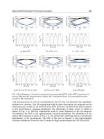
symmetric transmission geometry. Three Si-slabs of different cuts were used
(see Fig. 27.2). All three slabs then permit simulation of forbidden primary
reflections 222 or 002.
Fig. 27.2. Schematic diagram displaying the cuts of the used crystal slabs
462 P. Mikula et al.
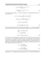
Fig. 27.3. Coordinate system describing the MBR reflection occurring with the
primary reflection
27.3 Calculation
From the geometry shown in Fig. 27.3 it is possible to derive the following
relations
n
αβγ
g
1
= |g
1
|sinθ
n
αβγ
g
hkl
= |g
hkl
|sinψ
n
αβγ
b = |b|cosθ,
(27.1)
where |n
αβγ
| = 1 from the definition and
sin ψ =(d
1
/d
hkl
)sinθ (27.2)
is given from the Bragg condition (d is the lattice spacing). Then, for crystal
slabs used in our experiment we could derive the relations providing Bragg
angles θ of the primary reflection where secondary reflection represented by
the Miller indices h, k, l can participate in the MBR-process.
1. For the crystal slab with the largest surface parallel to (1
10) and the longest
edge parallel to [111]
tan θ =(3/2)
1/2
(−h + k)/[(h
2
+ k
2
+ l
2
)/m − h −k − l]. (27.3)
2. For the crystal slab with the largest surface parallel to (11
2) and the longest
edge parallel to [111]
tan θ =(1/2)
1/2
(−h − k +2l)/[(h
2
+ k
2
+ l
2
)/m − h −k − l]. (27.4)
3. For the crystal slab with the largest surface parallel to (1
10) and the longest
edge parallel to [001]
tan θ =(1/2)
1/2
(−h + k)/[(h
2
+ k
2
+ l
2
)/m − l]. (27.5)
27 Neutron Multiple Reflections Excited in Cylindrically BPC 463
The parameter m in the relations (27.3)–(27.5) means the order of the
primary reflection.
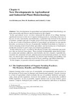
Using the formulae (27.3)–(27.5), in the range of θ − 2θ
D
scans one can
easily identify a lot of secondary and tertiary reflections participating in
MBR-process with respect to a chosen primary reflection. However, when
setting the crystal in the polychromatic incident beam, similarly to a sin-
gle reflection case, the presence of higher (or lower) orders can be found.
For example, if in our case we are interested in MBR studies with respect
to a forbidden primary Si(222) reflection, in many cases one can also find
an accompanied MBR-effect with respect to the primary reflections Si(111),
Si(333), Si(444) etc., simultaneously. In practice, all undesirable higher (or
lower) order contributions can be eliminated, e.g., by a neutron wavelength
selector. Sometimes, the wavelength distribution of neutrons passing through
the neutron guide can be favorable, when undesirable higher order contribu-
tions could be automatically eliminated, because their corresponding shorter
wavelength neutrons are not present in the spectrum. Therefore, in our case
we omitted all MBR-contributions corresponding to the neutron wavelengths
smaller than 0.08 nm. Furthermore, one should consider that the reflection
probability related to individual secondary and tertiary reflections is rather
small for shorter neutron wavelengths [19, 20]. Contrary to the mosaic crys-
tals, in our case of bent crystals for a detailed estimation of the individual
MBR-contributions the value of |g
2,3
·u|/(|u|·|g
2,3
|) plays also an important
role [18].
27.4 Search for Strong Multiple Bragg Reflection Effects
The experimental search of the MBR-effects appearing at different wave-
lengths was done on the two axis POLDI diffractometer installed at the end
of the thermal neutron guide in GKSS Geesthacht. The Si-slab was situated
in the white beam in the place of the monochromator. Having at a disposal
three cylindrically bent Si-crystal slabs of different cut, after setting them for
symmetric transmission, we carried out θ − 2θ
D
scans in the θ-range from
7
◦
to 60
◦
(for one azimuthal position) with the largest surface of the crystal
perpendicular to the primary scattering plane. In such a case the deformation
brought about by bending had no influence on the reflectivity of the primary
reflection but a strong effect on the secondary and tertiary reflections partici-
pating in MBR-process. Figures 27.4–27.6 display parts of the individual scans
where the MBR-effects were strongly excited. For the sake of comparison, the
scans with a flat nonbent crystal as well as the background are also intro-
duced in Fig. 27.4. It should be pointed out that the individual crystal slabs
are of different thickness whose parameter is also very important for a final
estimation of the reflectivity power of the MBR-monochromator. Simply, it
can be said that the intensity of the MBR-effect is linearly proportional to the
crystal thickness. Then, of course, the divergence Δθ and the Δλ spread of the
464 P. Mikula et al.
diffracted beam correspondingly increase. It should be pointed out that before
some practical use of the MBR- monochromator, an optimization procedure
of the curvature with respect to the individual MBR-effects should be carried
out. On the basis of the relations (27.3)–(27.5), we could easily determine the
secondary and tertiary planes contributing to the observed MBR-effects as
well as the corresponding Bragg angles θ. Table 27.1 shows the results corres-
ponding to the first four strongest peaks from the Fig. 27.4 which are related
Table 27.1. Calculated reflections and the Bragg angles of the strongest peaks
Peak N. Primary, secondary, θ/deg Peak N. Primary, secondary, θ/deg
tertiary reflections tertiary reflections
1 111/513/602 11.536 2 111/133/224 13.763
1 111/062
/153 11.536 2 111/151/040 13.763
1 111/5
33/624 11.536 2 111/400/511 13.763
1 111/2
64/353 11.536 2 111/224/313 13.763
1 111/3
13/404 11.536 3 111/153/242 14.705
1 111/044/133
11.536 3 111/422/513 14.705
1 111/3
73/462 11.536 4 222/311/513 29.956
1 111/6
42/733 11.536 4 222/313/511 29.956
1 111/133/022
11.536 4 222/151/133 29.956
1 111/2
02/313 11.536 4 222/153/131 29.956
Fig. 27.4. Part of θ − 2θ
D
scan with the crystal slab (the largest face parallel to
(110)) set for (hhh)
1
reflections in the symmetric transmission geometry