Modern Developments in X-Ray and Neutron Optics Episode 13 doc
Bạn đang xem bản rút gọn của tài liệu. Xem và tải ngay bản đầy đủ của tài liệu tại đây (2 MB, 40 trang )
480 A. Erko et al.
grating can, in general, no longer be described as the superposition of two inde-
pendent diffraction structures but instead by a complex volume interference
phenomena.
Several methods have been developed for the meridional grating cal-
culations. A description in the kinematic approximation, which neglects
interactions between incident and diffracted beams, was used by several
authors [18]. In the calculations [19], rigorous theory based on Maxwell’s
equations which take into account this interaction (dynamical theory) was
used. Computations can be done using a differential method and modal the-
ory [20]. In the modal theory, the solution is sought for the whole structure.
Therefore, structures with any number of layers can be calculated at the same
time. In addition, using this method, one can quickly compute the dispersive
curves in reciprocal space and the Bragg angle scanning of the diffracted
orders. However, this method is valid only for a lamellar grating. It is not
applicable, for example, for a sawtooth profile grating. In the present chapter,
the differential technique, developed in [21], is used for multilayer merid-
ional Bragg–Fresnel grating calculations. These calculations are carried out
layer-by-layer, making the method suitable for any kind of profile. Lamel-
lar gratings have been studied by several authors both theoretically and
experimentally [22–25].
The nature of diffraction on a three-dimensional grating/multilayer struc-
ture strongly depends on the optical properties of the materials and the
characteristic size of a grating period with the ‘lattice parameter’ a
1
and
a multilayer period with the ‘lattice parameter’ a
2
. As a consequence, two
different approximations can be used for different limiting conditions.
Multilayer Etched Meridional Grating
In the first approximation, the ‘double dispersion’ phenomena of multilayer
gratings can be described as a combination of Bragg diffraction on reflecting
layers and surface diffraction on a planar grating. In this simplest case, Bragg
diffraction limits the output energy and the angular spectra of the reflected
beam, and the planar grating produces an additional angular dispersion. The
measurements of meridional gratings with a ‘large’ period, which exceeds cri-
teria described later, show a simple combination of grating and multilayer, as
if they were used separately, one after other, similar to a surface grating. The
detector scan spectrum at the fixed Bragg angle, Θ
B
, shows several diffraction
peaks from the surface grating inside the broad Bragg peak of the multilayer
mirror. The property of the ‘short’ period, etched volume grating is not the
simple ‘overlapping’ of the two independent structures. Instead, one must refer
to the theory of crystal diffraction. The characteristics of a volume grating
can be demonstrated by the dependence of the absolute efficiency of the +1
order on the depth of the grating profile with a lamellar grating period being
taken as the variable parameter. These curves are shown in Fig. 28.5. For
28 Volume Modulated Diffraction X-Ray Optics 481
Fig. 28.5. Maximum efficiency of the +1 diffraction order vs. the number of etched
periods. The W/Si multilayer mirror is performed with 100 bilayers with a period
of 3 nm
the calculations, the same multilayer parameters as used for calculations of a
surface grating were taken by using (28.8).
According to the differential method for relatively large grating periods (in
the range of 200–20 μm), one can observe a peak of efficiency that corresponds
to an appropriate phase condition for both sagittal and meridional gratings.
The value for the optimal depth, obtained using the differential method, agrees
very well with the optimal depth calculated by the analytical formula (28.4)
for a sagittal grating.
The value of the ‘resonance phase’ depends on the mean value of the refrac-
tive index of a multilayer structure,
δ, and corresponds to the extinction depth
in a multilayer. Properties of such gratings are the same as for conventional
reflection phase gratings, except for the Bragg selectivity. For short period
gratings, i.e. with lateral periods of less than 10 μm, the behavior is different.
The aforementioned W/Si multilayer with the spacing of 3 nm is an example.
According to the differential model the ‘phase peak’ of efficiency is shifted into
the depth of the multilayer, and the +1 order intensity continuously increases
with the increasing depth of the grating profile (Fig. 28.5). This phenomenon
cannot be explained without involving volume diffraction effects.
Let us describe a multilayer grating as a two-dimensional crystal with two
different translation vectors, a
1
in the direction along a surface (X) and a
2
in the depth of a multilayer (crystal) (Z). Such a macro-crystal has two main
crystallographic directions along the z and x axes. The multilayer crystal
structure is shown schematically in Fig. 28.6. As in a natural crystal with
two different lattice parameters, one can define crystallographic directions
482 A. Erko et al.
Fig. 28.6. Schematic representation of a ‘multilayer crystal’
corresponding to different translation vectors of the lattice with an absolute
value of ha
1
and ka
2
.
Using crystallographic indexes one can define diffraction parameters d
h,k
for a short period grating (a
2
∼
=
a
1
)as
d
h,k
=
a
1
a
2
(ha
1
)
2
+(ka
2
)
2
. (28.13)
For a long period grating (a
2
<< a
1
) an effective diffraction occurs only
between waves diffracted from the top and the bottom of the grooves. A phase
shift between these waves depends only on the different optical paths in the
multilayer groove and vacuum. Multilayer mirrors act like a monochromatic
reflector with the phase reflecting grating on the top. The properties are the
same as for a sagittal grating with a period of d
h,k
≈ a
1
.Lookingatthe
efficiency dependence vs. the depth of the etched profile (Fig. 28.5), one can
see an increase in the absolute reflectivity up to 0.3, which corresponds to the
phase maximum (π phase shift) between diffracted waves. Diffraction orders
are located inside of a multilayer Bragg peak and cannot be observed without
zero order diffraction.
One can define these two limiting cases even more precisely taking into
account the extinction depth of a multilayer or crystal structure (28.11). As
already mentioned, for a sagittal grating the depth of profile is optimal if it
is equal to the value of extinction depth, t
z
ext
. Extending the definitions, one
can introduce an extinction depth value for the grating along the X direction,
which could be defined as
t
x
ext
≈
t
z
ext
sin(Θ
B
)
··· . (28.14)
The volume properties of a meridional etched grating become essential if the
period of a lateral grating is less than t
x
ext
. For example, a W/Si multilayer
28 Volume Modulated Diffraction X-Ray Optics 483
with a period of 3 nm and γ =0.3 has an extinction depth on the order of
50 nm at 0.154 nm wavelength. The corresponding ‘volume effect’ parameter
has a value of t
x
ext
∼ 1.95 μm. The same parameter for a Si(111) single crystal
reflection is equal to t
x
ext
∼ 5.3 μm.
The meridional multilayer grating properties have been experimentally
measured on lamellar multilayer grating samples having a variable grating
period and etching depth. All experimental measurements were performed in
the two-dimensional (Θ
i
− Θ
d
) scan mode at the energy of 8 keV (Fig. 28.3).
In this mode, the diffracted field was scanned with the detector slit at the
angle Θ
d
for each incident angle, Θ
i
, in order to record the intensity of all
‘n’orders.
The diffracted efficiency distribution in three dimensions vs. incident Θ
i
as well as the diffracted 2Θ
i
angle was measured and plotted. As an example,
Fig. 28.7 represents the results of the grating measurements in the detector
scan mode for the 230 nm profile depth and 4 μm grating period. The angle
of incidence was in the range of 1.5
◦
–1.65
◦
. For each incident angle, Θ
i
,the
diffracted field was scanned with the detector slit in the same range. Using
such a method, diffraction orders −2, −1, 0, +1, +2 can easily be resolved
(see Fig. 28.7).
As can be seen from this plot, the maximum intensity for the minus first
diffraction order corresponds to the minimum of the zero order. A similar
result was described by Neviere [26] for another type of multilayer grating,
one coated on large period blaze echelette grating. In that paper, the structure
Fig. 28.7. Θ
i
− Θ
d
plot in the detector scan mode for the meridional multilayer
grating with a profile depth of 230 nm
484 A. Erko et al.
of the multilayer grating was totally different from our structure, which is a
short period lamellar grating etched in a multilayer.
To measure the depth dependence of the diffraction efficiency, seven points
on the grating with a variable profile have been tested experimentally.
28.3 Dynamic Diffraction Gratings
based on Surface Acoustic Waves
This chapter presents the application of a surface acoustic wave (SAW) of
the Rayleigh type as a diffraction grating for X-ray radiation. Propagation
of SAWs in the crystal leads to the sinusoidal modulation of a crystal lattice
and sinusoidal modulation of a crystal surface. Since the phase velocity of the
SAW (2,000–4,000 m s
−1
) is much lower than the speed of the X-rays, the
acoustic deformation can be considered as quasi-static and characterized by
its wavelength and amplitude. However, the use of an ultrasonic super-lattice
in the X-ray wavelength range has some limitations. First, it is necessary to
apply acoustic waves with a very short wavelength (Λ ∼ 1–10 μm) in order to
produce a large angular dispersion between diffraction satellites [27–32]. This
requirement is related to the large Bragg angles, Θ
B
, for the real piezoelectric
crystals such as quartz, LiNbO
3
, LiTaO
3
, La
3
Ga
5
SiO
14
, La
3
Ga
5.5
Ta
0.5
O
14
,
which lie between 3
◦
and 40
◦
. Therefore, it is attractive to use a multilayer
X-ray mirror under the Bragg angle on the order of 1
◦
[33–36] or in a total
external reflection mode (α
i
∼ 0.1
◦
–0.3
◦
) [37, 38], where the SAW with a
wavelength of Λ = 10–40 μm produces considerable angular dispersion with
X-rays. Total external reflection is interesting for two other reasons. First, a
high reflectivity, typically 90%, is possible. Second is the high efficiency of
scattering by the surface acoustic waves, the amplitude of which is nearly
comparable to the depth of the penetration of the evanescent X-ray wave of
the order of 10 nm.
It is also possible to control both the wavelength and the amplitude of a
dynamic SAW grating by changing the amplitude of the input high-frequency
electric signal and the excitation frequency. These possibilities can be used
to optimize the space–time modulation based on X-ray diffraction by surface
acoustic waves [39, 40].
28.3.1 The SAW Device
Figure 28.8a, b show the SAW device based on a piezoelectric crystal. To excite
a Rayleigh SAW, an interdigital transducer (IDT) is deposited on the crystal
surface by photolithography or e-beam lithography. An IDT transforms the
high-frequency signal into acoustic oscillations of the crystal lattice, which
propagate along the crystal surface. The SAW amplitude on the crystal sur-
face can be changed linearly from zero to several angstroms by varying the
amplitude of the high-frequency electrical voltage supplied by a high-frequency
28 Volume Modulated Diffraction X-Ray Optics 485
(a) (b)
Fig. 28.8. (a)SAWdevice.(b) SAW propagation in the YZ-cut of a LiNbO
3
crystal.
Λ=30μm
generator to the IDT. Figure 28.8b presents the scanning electron microscopy
image of the SAW propagation in the YZ-cut of a LiNbO
3
crystal with the
velocity of V =3,488 m s
−1
. The SAW with wavelength Λ = 30 μmwas
excited at the resonance excitation frequency f = 116.3 MHz. It is seen that
SAW behaves like a strongly periodic sinusoidal diffraction grating.
SAW propagation causes a sinusoidal deformation of the crystal lattice
and crystal surface in the first approximation. A Rayleigh SAW is actually
elliptically polarized, but in the case of a symmetric reflection geometry, in-
plane displacements of the crystal lattice do not influence diffraction. The
deformation involved in the diffraction process can be written as
h = h
0
u
1
sin(Kx), (28.15)
where K =2π/Λ is the SAW wave vector and h
0
is the SAW amplitude on
the crystal surface, which can be controlled by varying the input signal on
the IDT.
28.3.2 Total External Reflection Mirror Modulated by SAW
The diffraction of light by ultrasound has been investigated theoretically
[41,42] and experimentally [43–45]. Theoretical curves (see Figs. 28.10–28.12)
show excellent agreement with experimental results. A detailed description of
the diffraction theory on a surface grating can be found in [38].
Figure 28.9 depicts a double-crystal X-ray diffractometer used to study
X-ray diffraction on the surface of the YZ-cut of a LiNbO
3
crystal mod-
ulated by surface acoustic waves under total external reflection. An X-ray
tube with a rotating copper anode (Cu Kα radiation, λ =0.154 nm, run-
ning at 40 kV and 60 mA) was used as the source of X-ray radiation. A plane
X-ray wave behind a double Si(111) crystal-monochromator was collimated
by a 10 μm slit. For diffraction studies under total external reflection, the
crystal surface was treated by chemical dynamic polishing so that the rough-
ness does not exceed 1 nm. This treatment is very important because the
roughness decreases the value of the critical angle. An IDT with an 8 μm fin-
ger width that corresponds to a Λ = 32 μm SAW was deposited on the surface
486 A. Erko et al.
Fig. 28.9. Diagram of the double-crystal X-ray diffractometer
of the sample so that the SAW propagates along the Z axis with a velocity
V =3.488 km s
−1
. The resonance frequency of the IDT was f
0
= 109 MHz.
For the experiment described here the collimated plane X-ray wave falls on
the crystal surface modulated by the surface acoustic wave at the incident
angle Θ
i
=0.22
◦
, slightly below the experimentally measured critical angle of
the YZ-cut of a LiNbO
3
crystal, α
c
=0.30
◦
. The X-ray plane wave diffracts on
the ultrasonic superlattice so that the angular position of diffraction satellites
can be determined from the grating equation:
k cos Θ
m
= k cos Θ
i
+ mK, (28.16)
where k =2π/λ, K =2π/Λandm is the diffraction order.
According to (28.16), the X-ray radiation is expected to diffract on the
crystal surface modulated by the SAW so that the angular divergence should
be 0.090
◦
and 0.063
◦
for m =0andm =+1(−1), respectively. The diffracted
X-ray radiation is recorded by a scintillation detector behind a 10 μm slit. In
all results, the diffracted X-ray intensity was normalized to the intensity of
the incident beam.
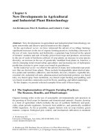
Figure 28.10 shows the experimental (a) and calculated (b) curves of the
diffracted X-ray radiation intensity, I, as a function of the detector scanning
angle, ΔΘ
d
, obtained at the X-ray incident angle ΔΘ
i
=0.22
◦
.Thereso-
nance excitation frequency of the SAW was f
0
= 109 MHz and values of the
amplitude of the input sinusoidal signal on the IDT ranged from U =2–17V.
The sinusoidal amplitude of the SAW, h, is a linear function of the amplitude
of the input signal on the IDT. In the calculated curves, h is assumed to be
between 0.2 and 1.7 nm. In Fig. 28.10, diffraction satellites are observed at the
angles ΔΘ
1
=0.090
◦
and ΔΘ
−1
=0.063
◦
from the intense reflected beam.
These values are in a good agreement with those calculated from expression
(28.15) for the −1 and +1 diffraction orders. The maximum intensity of the
m = −1 diffraction order makes up 10.5% of the intensity of the incident
X-ray beam for an amplitude of the input signal on the IDT U =17V.The
great difference in the diffraction order intensities (E
−1
>E
1
) and angular
28 Volume Modulated Diffraction X-Ray Optics 487
(a) (b)
Fig. 28.10. Experimental (a) and calculated (b) diffracted X-ray intensity I as a
function of the detector scanning angle ΔΘ
d
, obtained at the X-ray incident angle
Θ
i
=0.22
◦
, resonance excitation frequency of the SAW, f
0
= 109 MHz and at different
amplitudes of the SAW: U =2–17V
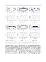
(a) (b)
Fig. 28.11. Experimental (a) and calculated (b) diffracted X-ray radiation intensity,
I, as a function of the detector scanning angle, ΔΘ
d
, obtained at the resonance
excitation frequency of the SAW f
0
= 109 MHz, amplitude of the input signal on
the IDT U = 17 V and at different values of the incident angle Θ
i
=0.15
◦
–0.37
◦
divergences between the diffraction orders (ΔΘ
−1
< ΔΘ
1
) is a consequence of
the small X-ray incident angle ΔΘ
i
=0.22
◦
. It is observed that the linewidth
is larger for the m = +1 peak, which is closer to the surface. This is an effect
of the divergence of the incident beam and can be understood by calculating
dΘ
m
/dΘ
i
from (28.16).
Figure 28.11 shows the experimental (a) and calculated (b) diffracted
X-ray radiation intensity, I, as a function of the detector scanning angle, ΔΘ
d
,
obtained at the resonance excitation frequency of the SAW, f
0
= 109 MHz,
with an amplitude of the input signal on the IDT, U = 17 V, and at differ-
ent values of the X-ray incident angle, ΔΘ
i
=0.15
◦
–0.37
◦
. In the calculated
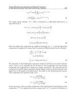
dependence, the sinusoidal amplitude, h, is assumed to be 1.7 nm. Figure 28.12
represents the experimental dependence and theoretical curves (full lines) of
the diffracted X-ray intensity, I, as a function of the incident angle, ΔΘ
i
,
obtained at the resonance excitation frequency of the SAW, f
0
= 109 Hz, and
at an amplitude of the input signal on the IDT, U = 17 V. These dependencies
(Figs. 28.11 and 28.12) demonstrate that the m =+1(−1) diffraction order
488 A. Erko et al.
Fig. 28.12. Diffracted X-ray intensity I as a function of the incident angle obtained
at the resonance excitation frequency of the SAW, f
0
= 109 MHz, and at an ampli-
tude of the input signal on the IDT U = 17 V. The full line shows the calculated
values
Fig. 28.13. Formation of the reflecting pseudo-lattices
has a maximum intensity at an incident angle of the X-ray beam of Θ
i
=0.22
◦
and 0.28
◦
, respectively.
28.3.3 Multilayer Mirror Modulated by SAW
The main restriction of the total external reflection technique is the generally
low efficiency of the diffraction satellites (around 20%) [38]. By using an X-ray
mirror this efficiency can be increased.
The next considerations help to predict which incident angle is likely to
favor a given diffraction order. Because of the presence of the acoustic wave,
the incident angle on the surface varies between ω −ϕ and ω + ϕ (Fig. 28.13).
Therefore, a strong Bragg reflection occurs if the incident angle, Θ, fulfills the
inequality
Θ
B
− ϕ<ω<Θ
B
+ ϕ ··· . (28.17)
This situation is indeed possible, since at an incident angle corresponding
to (28.17), some parts of the acoustic wave form a new family of reflecting
pseudo-planes, for which the Bragg condition is fulfilled (Fig. 28.13)
ω + ϕ =Θ
B
. (28.18)
28 Volume Modulated Diffraction X-Ray Optics 489
The multilayer interference X-ray mirror modulated by SAW thus acts
as a diffraction grating, reflecting the maximum intensity in the direction
determined by the angle β (Fig. 28.13):
β = ω +2ϕ ···. (28.19)
The incident angle, ω, giving a maximum intensity in the mth diffraction
order, can be determined from (28.15).
Solving (28.18) and (28.15), we obtain
cos ω − cos(2Θ
B
− ω)=mλ/Λ (28.20)
or, for small incident angles,
ω ≈ Θ
B
− mλ/2ΛΘ
B
, (28.21)
which is in a good agreement with experimental results. Note that (28.20)
is similar to the equation that gives the position of the peaks of maximum
intensity on the rocking curve.
The propagation of an X-ray wave in a multilayer interference X-ray mirror
modulated by surface acoustic waves can be investigated using the dynamic
diffraction theory in distorted crystals presented in [46–48]. In this case, the
multilayer acts as an artificial crystal. The deformation field in the crystal
(as in the theory of elasticity) is described by the vector u,representingthe
displacement of the atoms from the equilibrium position in the perfect crystal.
This displacement must satisfy some limitations, the same as in the case of
elastic wave propagation in a crystal. The next expression can be used to
describe the polarizability of the distorted crystal [49–51]
χ(r)=χ
∗
(r −u(r)), (28.22)
where χ
∗
is the polarizability of the perfect crystal and r is the radius-
vector [52–54].
TheX-raywavefieldinthecrystalcanbewrittenasasumofmodulated
waves:
E(r)=exp
−i
k
0
r
h
E
h
(r)exp
−i
hr
, (28.23)
where
k
0
is the wave vector of the incident wave and
h is the vector of the
reciprocal lattice.
The distribution of the X-ray wave field in the crystal in the case of two
strong waves is described by the following fundamental equations:
⎧
⎪
⎪
⎨
⎪
⎪
⎩
−
2i
k
0
∂E
0
∂s
0
= χ
00
E
0
+ χ
0h
exp
i
hu
E
h
,
−
2i
k
0
∂E
h
∂s
h
=(χ
00
− α) E
h
+ χ
h0
exp
i
hu
E
0
,
where χ
∗
hh
=
1
V
V
χ
∗
(r)exp
i
h
−
h
r
dr
(28.24)
490 A. Erko et al.
Fig. 28.14. Coordinate system for the calculation of the wave field in the multilayer
Fig. 28.15. Coordinate systems for the determination of the boundary conditions
are the Fourier coefficients of the polarizability; s
0
and s
h
are the unit vec-
tors along the refracted and diffracted waves (Fig. 28.14), α =
k
2
h
− k
2
0
k
2
0
;
and V is the volume of the unit cell. It is necessary to take into account
some boundary conditions: the continuity of the wave on the surface gives
(Fig. 28.15):
E
i
(r
e
)exp
−i
k
i
r
e
+
E
d
(r
e
)exp
−i
k
d
r
e
=
E
0
(r
e
)exp
−i
k
0
r
e
+
E (r
e
)exp
−i
k
h
r
e
,
(28.25)
where indices i,d and 0,h correspond to the incident and the diffracted waves
in the vacuum and in the crystal, respectively and r
e
is the radius-vector of
the input surface. In (28.25) it is also assumed that the incident angle is large
28 Volume Modulated Diffraction X-Ray Optics 491
enough to neglect the reflection. The following two equations are obtained
from (28.25):
⎧
⎨
⎩
E
0
(r
e
)=
E
i
(r
e
)exp
−i
k
i
−
k
0
r
e
E
d
(r
e
)=
E
h
(r
e
)exp
i
k
d
−
k
h
r
e
.
(28.26)
These relations describe the phase shifts that occur on the two inter-
faces: vacuum-crystal and crystal-vacuum. In the case of a non-plane interface,
this phase shift changes from one surface element to another and cannot be
neglected in the case of a multilayer mirror modulated by SAW.
The calculations of the real diffraction pattern are carried out using the
method described in [38]. Thus, we suppose that all the surface elements
on which the plane wave,
E
d
, falls act as secondary sources of spherical
waves:
E(p)=−
i
2λ
S
E
d
exp
−
k
d
r
e
e
ikr
r
cos
n
∧
,
k
d
−
−cos
n
∧
,
r
dS. (28.27)
Using (28.22) and taking into account that we investigate the diffracted
wave in the far field region (1/r ≈ const)
E(p)=−
icosα
λ
S
E
h
exp
−i
k
h
r
e
e
ikr
r
dS
=const
S
E
h
exp {−i[(k
hx
− k cos α) x +(k
hz
− k sin α) z]}dS,
(28.28)
where β is the diffraction angle, k =2π/λ, z = h sin Kx the amplitude of
the modulated surface, h the SAW amplitude, K =2π/Λ,Sthe modulated
surface. The exponential term describes the phase shift due to the refraction
on the crystal–vacuum interface.
The following equation is used to calculate the diffracted X-ray intensity
I = E(p)E
∗
(p) ··· . (28.29)
In the calculated intensities, the sinusoidal amplitude, h, of the SAW is
assumed to be 1.4 nm. Theoretical curves (see Figs. 28.18 and 28.19) show
good agreement with experiments.
The multilayer mirror was deposited on the YZ-cut of a LiNbO
3
crystal
treated initially by chemical dynamic polishing to decrease the roughness to
0.5 nm. The W/C multilayer was produced by magnetron sputtering. It is
made of 60 bilayers of 5.3 nm each. The Bragg angle of this multilayer is
Θ
B
=0.83
◦
.
An IDT for the SAW excitation with a 4 μm finger width corresponding
to Λ = 16 μm SAW wavelength was also deposited on the free surface of the
LiNbO
3
crystal. The SAW propagates along the Z axis with a velocity V =
3.488 km s
−1
. The resonance excitation frequency of the IDT is f
0
= 218 MHz.
492 A. Erko et al.
Fig. 28.16. Diffracted intensity as a function of the detector scanning angle ΔΘ
d
obtained at the Bragg incident angle for different amplitudes of the input signal on
the IDT
The diffracted X-ray intensity is recorded by a scintillation detector with
a10μm input slit.
Figure 28.16 shows the experimental curves of the diffracted X-ray radi-
ation intensity, I, as a function of the detector scanning angle, ΔΘ, where
ΔΘ
B
=0.823
◦
and for different values of the amplitude of the input sinu-
soidal signal on the IDT in the range of 1–17 V. The diffraction satellites are
observed at the angular deviations ΔΘ
+1
=0.039
◦
and ΔΘ
−1
=0.038
◦
from
the intense reflected beam. These values can be precisely predicted from the
grating equation.
The intensities of the m =+1, −1 satellites increase and the zero order
satellite decrease with the SAW amplitude. The maximum intensities of these
diffraction orders make up 7% of the intensity of the diffracted beam with-
out SAW excitation. The difference in the angular deviations between the
diffraction orders ΔΘ
+1
> ΔΘ
−1
is in agreement with (28.10).
Figure 28.17 presents rocking curves obtained with the detector placed in
the Bragg position ΔΘ
B
=0.823
◦
, and for different amplitudes of the input
signal on the IDT. The satellite intensities increase rapidly with the SAW
amplitude while the zero order peak decreases. In the case of U =17V,the
intensities of the +1, −1 satellites become higher than the zero order intensity.
At this voltage, the intensity in the +1 and −1 satellites reaches 68% of the
Bragg peak without SAW excitation.
Figure 28.18 shows the (a) experimental measurements and (b) calcula-
tions based on the model developed below for the diffracted X-ray intensity,
E, as a function of the detector scanning angle, ΔΘ
d
, for different incident
28 Volume Modulated Diffraction X-Ray Optics 493
Fig. 28.17. Rocking curves with the detector in the Bragg position for different
amplitudes of the input signal on the IDT
(a) (b)
Fig. 28.18. Experimental (a) and calculated (b) diffracted intensity as a function
of the detector scanning angle ΔΘ obtained for U =17V(h =1.4 nm) and for
various incident angles Θ between 0.792
◦
and 0.872
◦
angles. The m = ±1 diffraction orders reach a maximum intensity ∼58% for
an incident angle of Θ
i
=0.808
◦
and 0.848
◦
, respectively.
The same phenomena take place for the ±2 order satellites: the maximum
intensity ∼22% was obtained for an incident angles Θ
i
=0.792
◦
and 0.872
◦
.
This means that, to obtain the maximum energy diffracted towards a precise
satellite, it is necessary to lightly shift the incident angle away from the exact
Bragg angle of the multilayer.
In Fig. 28.19 are shown the experimental and calculated maximal intensi-
ties of the ±1 and 0 order peaks for various incident angles, Θ
i
.Themaximum
intensity in the diffraction orders corresponds to the minimum intensity of the
zero order, as was demonstrated previously for the volume gratings, etched in
a multilayer mirror (Fig. 28.7).
494 A. Erko et al.
Fig. 28.19. Maximum diffracted intensity of the +1, 0, −1 peaks as a function of
incident angle Θ
i
,f
0
= 218 MHz,U= 17 V. The solid line shows calculated values
28.3.4 Crystals Modulated by SAW
In contrast to acoustically modulated multilayer mirrors, a crystal, modulated
by SAW, acts much more effectively because, for the crystal, the value of
the SAW amplitude can exceed the interplanar spacing. The same diffraction
efficiency can be obtained with much lower acoustic amplitude than required
for an X-ray mirror. In this section the X-ray diffraction by langasite (LGS)
crystal, (La
3
Ga
5
SiO
14
), excited by SAW is presented.
Figure 28.20 shows the calculated amplitude of the crystal lattice dis-
placements in LGS caused by SAW propagation vs. crystal depth. The
calculation [55] is based on the elastic and piezoelectric properties of the
LGS [56]. It is seen that the SAW penetration depth inside the crystal is
approximately one SAW wavelength (see component u
1
normal to the crystal
surface). The longitudinal component, u
2
, is parallel to the direction of the
SAW propagation. The presence of the transverse displacement component,
u
3
, suggests that the propagation direction of the acoustic energy flow does
not coincide with the SAW wave vector direction.
X-ray diffraction on acoustically modulated atomic planes gives rise to
diffraction satellites on both sides of the Bragg peak. In case of symmet-
ric Bragg reflections, the angular position of diffraction satellites can be
determined from the grating (28.15).
The angle between adjacent satellites measured on a rocking curve can be
deduced from (28.15)
δΘ
mRC
= mλ/2Λ sin Θ
B
= md/Λ, (28.30)
where d is the interplanar spacing.
28 Volume Modulated Diffraction X-Ray Optics 495
Fig. 28.20. Calculated SAW amplitudes vs. crystal depth: normal (u
1
), longitudinal
(u
2
) and transverse components (u
3
)
LGS is a piezoelectric crystal of space group symmetry 32. The crystal
lattice is similar to that of quartz with the parameters a =0.817 nm and
c =0.5095 nm [57].
An X-cut, (110) atomic planes parallel to the crystal surface, of LGS was
used for this experiment. To excite a Rayleigh SAW, IDT was deposited on
the crystal surface by photolithography. At the resonance excitation frequency,
f
0
= 192.5 MHz, the SAW wavelength was λ =12μm and the propagation
velocity was V =2,310 ms
−1
.
Rocking curves were measured at various SAW amplitudes. The X-ray
energy was 11 keV. The interplanar spacing for the (110) reflection in LGS is
d =0.4087 nm. In the kinematic approximation the X-ray penetration depth
inside the crystal depends on the absorption in LGS as a function of energy
given by
μ
−1
z
(E)=sin(Θ
B
(E))/2μ
l
(E), (28.31)
where μ
l
is the linear absorption coefficient and Θ
B
is the Bragg incident
angle. This dependence is shown in Fig. 28.21. The K-edge of Ga at 10.47 keV
causes a drastic change in the absorption coefficient. At the energy of 11 keV,
the X-ray penetration depth reaches only μ
−1
z
=0.48 μm,whichismuchless
than the SAW penetration depth inside the crystal (μ
−1
z
/μ
−1
SAW
< 1).
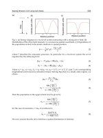
Figure 28.22 shows selected rocking curves for LGS (reflection (110))
excited by a Λ = 12 μm SAW at 11 keV measured at various input volt-
ages (U) supplied to the IDT. The Bragg incident angle is Θ
B
=7.92
◦
.The
FWHM of the Bragg peak without SAW excitation is 3.2 arcsec (Fig. 28.22a).
Figure 28.22 shows that the number of diffraction satellites observed on
the rocking curve increases with the amplitude of the input signal supplied to
the IDT, i.e. with the SAW amplitude.
496 A. Erko et al.
Fig. 28.21. X-ray penetration depth in an LGS crystal for (110) reflection vs.
energy. The black circle shows the energy 11 keV
(a) (b)
(c) (d)
Fig. 28.22. Rocking curves measured for different amplitudes of the input signal
supplied to the IDT: (a) U =0V,(b) U =8.5V, (c) U =14V,(d) U =18V
28 Volume Modulated Diffraction X-Ray Optics 497
Fig. 28.23. Intensities of the diffraction satellites (m =0, 1, 2, 3) vs. amplitude of
the input signal supplied to the IDT. Black circles, squares, triangles and diamonds:
experimental data. Solid lines: calculated data. E =11keV; Λ=12μm; (110)
reflection
The angular divergence between two neighboring diffraction satellites,
δΘ
mRC
, is 6.8 arcsec, which agrees quite well with the value 6.9 arcsec
calculated from (28.30).
Intensities of selected diffraction satellites (m =0, 1, 2, 3) as a function of
the input voltage on the IDT are shown in Fig. 28.23. The intensity of the
diffraction satellites, except for satellite m =0,developsassoonastheacous-
tic amplitude reaches a threshold value, which increases with the diffraction
order. After rapidly reaching a maximum, the satellite intensity decreases
smoothly and oscillates.
It can be seen (Fig. 28.22b) that the intensity of the m = 0 diffraction
satellite is equal to zero for U =8.5 V. For this specific SAW amplitude, the
phase shift of the X-ray radiation diffracting into the zero satellite from the
SAW minima and maxima regions (where the atomic planes are still parallel
to the surface) is equal to π. This phenomenon can be observed only if the
acoustic wave field probed by X-rays is very homogenous in amplitude. This
is, therefore, only possible if the X-ray absorption is strong enough to avoid
any interaction with deep regions of the crystal where the acoustic ampli-
tude is strongly damped. In the case of LiNbO
3
, the absorption is never high
enough to achieve the complete extinction of a satellite except in the case of
an asymmetric reflection for which the incident angle can be very small [29].
For U = 14 V, the extinction of the m =+1(−1) diffraction satellites
is observed and can also be explained by the π-phase shift between crystal
regions diffracting towards this satellite (Fig. 28.22c). The maximum value of
498 A. Erko et al.
the input signal amplitude is U = 18 V. At this amplitude, the intensity of the
m =+2(−2) diffraction satellite decreases, although no complete extinction
of these satellites occurs (Fig. 28.22d).
As calculated in [29], the intensity of the mth diffraction satellite is
proportional to
I
m
∝
∞
0
exp(−μ
z
z) J
m
(h
0
q
z
u
1
(z)) dz
2
, (28.32)
where J
m
is the mth order Bessel function. Figure 28.23 shows diffraction
satellite intensities (solid lines) vs. SAW amplitude calculated by (28.32).
There is good agreement between experimental results and calculations show-
ing that numerical calculations of u
1
based on the elastic and piezoelectric
tensors of the langasite crystal and on the Rayleigh wave characteristics are
correct. These results are much better than those for the case of SAW propaga-
tion in a LiNbO
3
crystal where kinematic simulations were useless especially
at low acoustic amplitudes and for 0 and 1 order satellites [29]. This dif-
ference can be explained by the fact that for the X-ray penetration depth,
being so small in a langasite crystal at 11 keV, the X-rays interact only with
strongly distorted regions of the crystal. If this was not the case, dynami-
cal theory should be necessary to take into account the contribution to the
diffracted intensity coming from deep non-distorted (i.e. perfect) regions of
the crystal [31].
References
1. A. Gupta, C. Meneghini, A. Saraiya, G. Principi, D.K. Avasthi, Nucl. Instrum.
Methods Phys. Res. B212, 458 (2003)
2. T.W. Barbee Jr., SPIE Proc. 911, 169 (1988)
3. V.V. Aristov, S.V. Gaponov, V.M. Genkin, Y.A. Gorbatov, A. Erko V.V.
Martynov, L.A. Matveeva, N.N. Salaschenko, JETPh Lett. 44(4), 265 (1986)
4. A. Erko, in Materials Science Forum, vol. 321–324 (Trans Tech Publications,
Switzerland, 2000), pp. 174–178
5.A.Erko,V.V.Aristov,B.Vidal,Diffraction X-Ray Optics (IOP Publishing,
Bristol, 1996)
6. A. Firsov, A. Svintsov, A. Erko, W. Gudat, S. Kuznetsov, M. Grigoriev, A.
Asryan, M. Ferstl, S. Shapoval, V.V. Aristov, Nucl. Instrum. Methods Phys.
Res. A467–A468, 366 (2001)
7. A.Firsov,A.Svintsov,S.I.Zaitsev,A.Erko,V.V.Aristov,Opt.Commun.202,
55 (2002)
8. A. Erko, A. Firsov, Proc. SPIE 5539, 148 (2004)
9. A.I. Erko, B. Vidal, P. Vincent, Y.A. Agafonov, V.V. Martynov, D.V.
Roschupkin, M. Brunel Nucl. Instrum. Methods Phys. Res. A333, 599 (1993)
10. A. Erko, Y.A. Agafonov, L.A. Panchenko, A. Yuakshin, P. Chevallier, P. Dhez,
F. Legrand, Opt. Commun. 106, 146 (1994)
28 Volume Modulated Diffraction X-Ray Optics 499
11. P. Vincent, in Electromagnetic Theory of Gratings, ed. by R. Petit. Topics
in Current Physics, vol. 22, (Springer, Berlin Heidelberg New York, 1980)
pp. 101–121
12. E. Aristova, Ch. David, A. Freund, Ya. Hartman, B. Kaulich, A. Snigirev, V.
Yunkin, in X-Ray Microscopy IV, ed by V.V. Aristov, A.I. Erko, (Bogorodskii
Pechatnik, 1994) pp. 617–620
13. V.G. Kohn, The Theory of X-Ray Bragg-Fresnel Focusing by Flat and
Elastically Bent Lens, Preprint IAE-5878/9. M., (1995)
14. V.V. Aristov, A.I. Erko, A.Y. Niculin, A.A. Snigirev, Opt. Commun. 58, 300
(1986)
15. Ya. Hartman, A. Freund, A. Snigireva, A. Snigirev, A. Souvorov, Nucl. Instrum.
Methods Phys. Res. A385, 371 (1997)
16. Ya. Hartman, V.A. Yunkin, A. Snigirev, J. X-Ray Sci. Technol. 6, 249 (1996)
17. A. Erko, A. Firsov, Proc. SPIE 5539, 148 (2004)
18. A. Pardo, J M. Andre, A. Sammar, J. Opt. (Paris), 22(3), 141 (1991)
19. A. Sammar, J M. Andre, J. Opt. Commun. 86, 245 (1991)
20. M. Brunel, A.I. Erko, V.V. Martynov, B. Vidal, P. Vincent, A. Yuakshin, D.V.
Roshchoupkin, Nucl. Instrum. Methods Phys. Res. A339, 617 (1994)
21. B. Vidal, P. Vincent, P. Dhez, M. Neviere, Proc. SPIE, 556, 142 (1985)
22. S. Bat, G. Soullie, A. Mirone, M. Idir, P. Gukrin, F R. Ladan, P. Troussel,
R. Barchewitz, B. Vidal, Opt. Commun. 144, 28l (1997)
23. V.A. Chernov, V.I. Erofeev, N.I. Chkhalo, N.V. Kovalenko, S.Y. Mytnichenko,
Nucl. Instrum. Methods Phys. Res. A405, 310 (1998)
24. V.V. Martynov, Yu. Platonov, Rev. Sci. Instrum. 73, 1551 (2002)
25. V.A. Chernov, V.I. Erofeev, N.I. Chkhalo, N.V. Kovalenko, S.Y. Mytnichenko,
Nucl. Instrum. Methods Phys. Res. A359, 138 (1995)
26. M. Neviere, J. Opt. Soc. Am. A8, 1468 (1991)
27. R. Tucoulou, R. Pascal, M. Brunel, O. Mathon, D.V. Roshchupkin, I.A.
Schelokov, E. Cattan, D. Remiens, J. Appl. Crystallogr. 33, 1019 (2000)
28. W. Sauer, M. Streibl, T.H. Metzger, A.G.C. Haubrich, S. Manus, A. Wixforth,
J. Peisl, Appl. Phys. Lett. 75, 1709 (1999)
29. R. Tucoulou, F. de Bergevin, O. Mathon, D. Roshchupkin, Phys. Rev. B64,
134108(9) (2001)
30. D.V. Roshchupkin, D.V. Irzhak, R. Tucoulou, O.A. Buzanov, J. Appl. Phys. 94,
6692 (2003)
31. I.A. Schelokov, D.V. Roshchupkin, D.V. Irzhak, R. Tucoulou, J. Appl.
Crystallogr. 37, 52 (2004)
32. R. Tucoulou, O. Mathon, C. Ferrero, V. Mocella, D.V. Roshchupkin, R.E.
Kumon, J. Appl. Phys. 97, 113505(5) (2005)
33. A.I. Erko, D.V. Roshchupkin, A.A. Snigirev, A.M. Smolovich, A. Yu Nikulin,
G.V. Vereshchagin, Nucl. Instrum. Methods Phys. Res. A282, 634 (1989)
34. D.V. Roshchupkin, I.A. Schelokov, R. Tucoulou, M. Brunel, Nucl. Instrum.
Methods Phys. Res. B129, 414 (1997)
35. R. Tucoulou, D.V. Roshchupkin, I.A. Schelokov, M. Brunel, L. Ortega,
E. Ziegler, M. Lingham, C. Mouget, S. Douillet, Nucl. Instrum. Methods Phys.
Res. B132, 207 (1997)
36. R. Tucoulou, D.V. Roshchupkin, O. Mathon, I.A. Schelokov, M. Brunel,
E. Ziegler, C. Morawe, J. Synch. Radiat. 5, 1357 (1998)
37. D.V. Roshchupkin, M. Brunel, F. de Bergevin, A.I. Erko, Nucl. Instrum.
Methods Phys. Res. B72, 471 (1992)
500 A. Erko et al.
38. D.V. Roshchupkin, I.A. Schelokov, R. Tucoulou, M. Brunel, IEEE Trans.
Ultrason. Ferroelectrics Freq. Contr. 42(1), 127 (1995)
39. D.V. Roshchupkin, M. Brunel, Rev. Sci. Instrum. 64(2), 379 (1993)
40. R. Tucoulou, M. Brunel, D.V. Roshchupkin, I.A. Schelokov, Rev. Sci. Instrum.
69(7), 2704 (1998)
41. J.W.S. Rayleigh, Theory of Sound, vol. 2 (Dover, New York, 1945)
42. A. Yariv, P. Yeh, Optical Waves in Crystals (Wiley, New York, 1984)
43. E. Salzmann, D. Weismann, J. Appl. Phys. 40, 3408 (1969)
44. E.P. Ippen, Proc. IEEE 55, 245 (1967)
45. A. Yariv, Optical Electronics (Holt, Renehart and Winston, New York, 1985)
46. S. Takagi, Acta Cryst. 15, 1131 (1962)
47. S. Takagi, J. Phys. Soc. Jpn. 26, 1239 (1969)
48. A.M. Afanas’ev, V.G. Kohn, Acta Cryst. A27, 421 (1971
49. N. Kato, J. Phys. Soc. Jpn. 18, 1785 (1963)
50. N. Kato, J. Phys. Soc. Jpn. 19, 67 (1963)
51. N. Kato, J. Phys. Soc. Jpn. 19, 971 (1963)
52. N. Kato, J. Phys. Soc. Jpn. 18, 1785 (1963)
53. N. Kato, J. Phys. Soc. Jpn. 19, 67 (1963)
54. N. Kato, J. Phys. Soc. Jpn. 19, 971 (1963)
55. E. Dieulesaint, D. Royer, Ondes Elastique dans les Solids (Masson, Paris, 1974)
56. J. Bohm, E. Chilla, C. Flannery, H J. Fr¨ohlich, T. Hauke, R.B. Heimann,
M.Hengst,U.Straube,J.Cryst.Growth216, 293 (2000)
57. E. Chilla, C.M. Flannery, H J. Fr¨ohlich, U. Straube, J. Appl. Phys. 90, 6084
(2001)
29
High Resolution 1D and 2D Crystal Optics
Based on Asymmetric Diffractors
D. Koryt´ar, C. Ferrari, P. Mikul´ık,F.Germini,P.Vagoviˇc,
and T. Baumbach
Abstract. The development of high resolution X-ray measurements and imaging
in real and reciprocal space is related to the improvement of the optical elements
available for use. Crystal diffractive optics still give the highest resolution in recip-
rocal space and in energy, and progress has also been made in improving resolution
in real space. In this chapter a short introduction to the dynamical theory behind
crystal diffractors and their coupling is given and modern one- and two-dimensional
elements based on symmetric, asymmetric and inclined diffractions are introduced.
The design, the modeling of the output parameters and the experimental results
are presented for a special 2-bounce V-shaped monochromator, for a monolithic
4-bounce monochromator and for a monolithic 2D beam de/magnifier.
29.1 Introduction
The optical scheme of a high-resolution X-ray diffractometer (HRXRD)
includes an X-ray source (laboratory or synchrotron), beam conditioning
optics, sample, analyzer, and detector. A compromise must be found between
high intensity on one side and high resolution in real and reciprocal space
or high energy resolution on the other side. The best resolution in reciprocal
space is achieved with crystal X-ray optics based mainly on Bragg diffraction
from perfect crystals such as silicon and germanium. Si(111) double crystal
monochromators for synchrotron and Ge (220/440) Bartels type monochroma-
tors for laboratory sources are typical examples. High resolution in reciprocal
space is given by the small widths of Bragg diffraction peaks of these crys-
tals, approaching theoretical values in the arcsec range as given by dynamical
theory of X-ray diffraction. The full width at half maximum of these peaks
can be further decreased using asymmetric diffraction in a grazing incidence
setting. This setting is also known as a one-dimensional (1D) beam expander
in real space. Combining two asymmetric diffractors with mutually perpen-
dicular scattering planes a two-dimensional (2D) image magnification can be
obtained.
502 D. Koryt´ar et al.
This chapter gives a short introduction to modern 1D and 2D crystal optics
for high-resolution diffractometry and imaging which are based on asymmetric
diffractors. It describes channel-cut monochromators and monolithic 2D beam
de/magnifiers, the theoretical background used in their design, the modeling
of their parameters using the DuMond diagrams and the spectral functions,
and beam tracing, as well as the experimental results obtained mainly with
monolithic devices.
29.2 Scattering Geometries and Crystal Diffractors
There are various scattering geometries used for the X-ray diffraction char-
acterization of crystals and thin layers. In the elastic scattering process the
incident monochromatic plane wave with wavevector K
0
is elastically scat-
teredintoawavewiththewavevectorK,where|K
0
| = |K| = K =2π/λ,and
λ is the wavelength. This process is characterized by the scattering vector (or
wavevector transfer) Q = K − K
0
.
In a crystal or in a crystal diffractor, which is the physical part of a crystal
characterized by the reciprocal lattice vector H
hkl
and the in-crystal surface
normal n, which is used to diffract the incident X-ray beam with wavevec-
tor K
0
, (see Fig. 29.1), most of the scattered intensity is located in a small
region surrounding the reciprocal lattice point, H. Such lattice points are
characterized by corresponding lattice vectors H = H
hkl
= OH,where
|H
hkl
| =2π/d
hkl
and d
hkl
is the interplanar distance of the lattice planes
(hkl). The structure factor, F
hkl
, determines the amplitude of the scattered
wave. The purpose of reciprocal space mapping is to determine the scattered
(a) (b)
Fig. 29.1. A flat crystal X-ray diffractor in real (a) and reciprocal (b)space
29 High Resolution 1D and 2D Crystal Optics 503
intensity in reciprocal space. The kinematical theory of X-ray diffraction in
an infinite crystal leads to the Bragg law in the vectorial form
K
H
− K
0
= H (29.1)
and implies the concept of Ewald sphere [1]. The scalar Bragg law has the form
2d
hkl
sin θ
B
= λ, (29.2)
where θ
B
is the Bragg angle between the incident or the diffracted beam and
diffracting planes.
If n is the in-crystal surface normal, the plane of incidence (K
0
, n)isgen-
erally not parallel to the dispersion plane (n, H),andwehaveanoncoplanar
geometry.Inthecoplanar geometry,wheretheplane of incidence is paral-
lel to the dispersion plane, the reciprocal space maps of scattered intensity
are functions of Q while in the noncoplanar case this intensity depends on
both vectors K
0
and K
H
independently [7]. In the semiinfinite crystal, due
to the presence of the vacuum-crystal interface, there is additional scatter-
ing from this interface which modifies the vacuum waves K
0
and K
H
into the
in-crystal (refracted)wavesk
0
and k
H
. The requirement of momentum conser-
vation leads to the continuity of the tangential component of the wavevectors
(the in-crystal and vacuum wavevectors differ only by a component along the
surface normal n)
k
0
= K
0
+ κn (29.3)
k
H
= K
H
+ κ
H
n = K
0
+ H + κ
H
n. (29.4)
The quantities κ and κ
H
have a magnitude of about ∼K|χ
0
|/2, where χ
0
is expressed generally by (29.10) (see below). Using (29.3) and (29.4) the
wavevector of the diffracted wave in vacuum can be expressed as
K
H
= K
0
+ H
,whereH
= H + Δ
H
, Δ
H
= Δ
H
n,whereΔ
H
= κ−κ
H
.
The additional momentum transfer, Δ
H
, at the vacuum-crystal interface can
be expressed as
Δ
H
= K
−γ
H
±
γ
2
H
− α
H
, (29.5)
where γ
H
=
(K
0
+ H) · n
K
= γ
0
+
(H · n)
K
,γ
0
=
K
0
·n
K
(29.6)
are the directional cosines of the vector K
0
+ H and K
0
, respectively, with
respect to the inward crystal surface normal, n,and
α
H
=
2K
0
· H + H
2
K
2
. (29.7)
This dimensionless parameter is a function of the magnitude and the direction
of K
0
relative to H. The direction cosine of the diffracted beam K
H
is
γ
H
=
K
H
· n
K
= ±
γ
2
H
− α
H
. (29.8)
504 D. Koryt´ar et al.
The general expressions above can be simplified for special cases such as
symmetrical, asymmetrical, symmetrical inclined, and asymmetrical inclined
cases. Two additional important cases, which are not covered by the usual
approaches, are for a Bragg angle close to 90
◦
and for an extreme asymmetry
with the angle of incidence close to the critical angle. These are described
in [18].
29.3 Basic Results of Dynamical Theory
Historically, several approaches have been taken to solve the problem of the
scattering of an incident X-ray wave by a crystal. One of them is to solve
Maxwell’s equations for a plane monochromatic electromagnetic radiation
wave E(r,t)=E
i
exp[i(K
0
r − ωt)] scattered by a medium with an elec-
tric susceptibility χ(r). The susceptibility is a continuous function with the
periodicity of the crystal lattice
χ(r)=Σχ
H
exp(iHr), (29.9)
where
χ
H
= −
r
e
F
H
πV
λ
2
(29.10)
are its Fourier components (generally complex), r
e
is the classical radius of
electron, F
H
the structure factor of the crystal unit cell and V is the volume
of the unit cell. The solution gives a Bloch wave
D(r)=
H
D
H
e
ik
H
r
(29.11)
inside the crystal, composed of an infinite number of plane waves k
H
= k
0
+H.
The amplitudes of the electric induction vectors D
H
obey the system of
fundamental equations of the dynamical theory
k
2
H
− K
2
K
2
D
H
=
H
χ
H−H
D
H
(29.12)
from which it comes that the only significantly excited component waves
are those for which k
H
∼ K|1+χ
0
|/2, which is called the excitation con-
dition. Single-, two-, three- and multiple- beam diffraction can occur. We will
concentrate on two-beam cases.
For the two-beam case, the condition for the existence of a nonzero solution
(determinant of the system of linear equations (29.12) equal to zero) leads to
the dispersion equation in the form [9]
k
2
0
χ
p
− K
2
k
2
H
χ
p
− K
2
= C
2
k
2
0
k
2
H
χ
H
χ
¯
H
, (29.13)