Applied Radiological Anatomy for Medical Students Applied - part 1 docx
Bạn đang xem bản rút gọn của tài liệu. Xem và tải ngay bản đầy đủ của tài liệu tại đây (294.13 KB, 15 trang )
This page intentionally left blank
Applied Radiological Anatomy for Medical Students
Applied Radiological Anatomy for Medical Students is the definitive atlas of
human anatomy, utilizing the complete range of imaging modalities
to describe normal anatomy and radiological findings.
Initial chapters describe all imaging techniques and introduce the
principles of image interpretation. These are followed by
comprehensive sections on each antomical region.
Hundreds of high-quality radiographs, MRI, CT and ultrasound
images are included, complemented by concise, focused text. Many
images are accompanied by detailed, fully labeled, line illustrations to
aid interpretation.
Written by leading experts and experienced teachers in imaging
and anatomy, Applied Radiological Anatomy for Medical Students is an
invaluable resource for all students of anatomy and radiology.
paul butler is a Consultant Neuroradiologist at The Royal London
Hospital, London.
adam w. m. mitchell is a Consultant Radiologist at Charing Cross
Hospital, London.
harold ellis is a Clinical Anatomist at the University of London.
Applied Radiological
Anatomy for Medical Students
PAUL BUTLER
The Royal London Hospital
Edited by
ADAM W. M. MITCHELL
Charing Cross Hospital
HAROLD ELLIS
University of London
CAMBRIDGE UNIVERSITY PRESS
Cambridge, New York, Melbourne, Madrid, Cape Town, Singapore, São Paulo
Cambridge University Press
The Edinburgh Building, Cambridge CB2 8RU, UK
First published in print format
ISBN-13 978-0-521-81939-8
ISBN-13 978-0-511-36614-7
© Paul Butler, Adam W. M. Mitchell and Harold Ellis 2007
2007
Information on this title: www.cambridge.org/9780521819398
This publication is in copyright. Subject to statutory exception and to the provision of
relevant collective licensing agreements, no reproduction of any part may take place
without the written
p
ermission of Cambrid
g
e University Press.
ISBN-10 0-511-36614-0
ISBN-10 0-521-81939-3
Cambridge University Press has no responsibility for the persistence or accuracy of urls
for external or third-party internet websites referred to in this publication, and does not
g
uarantee that any content on such websites is, or will remain, accurate or a
pp
ro
p
riate.
Published in the United States of America by Cambridge University Press, New York
www.cambridge.org
paperback
eBook (EBL)
eBook (EBL)
paperback
Contents
List of contributors vii
Acknowledgments ix
Section 1 The basics
1 An introduction to the technology of imaging 1
thomas h. bryant and adam d. waldman
2 How to interpret an image 17
adam w. m. mitchell
Section 2 The thorax
3 The chest wall and ribs 23
jonathan d. berry and sujal r. desai
4 The breast 31
stella comitis
Section 3 The abdomen and pelvis
5 The abdomen 36
dominic blunt
6 The renal tract, retroperitoneum and pelvis 47
andrea g. rockall and sarah j. vinnicombe
Section 4 The head, neck, and vertebral column
7 The skull and brain 64
paul butler
8 The eye 81
claudia kirsch
9 The ear 86
claudia kirsch
10 The extracranial head and neck 91
jureerat thammaroj and joti bhattacharya
11 The vertebral column and spinal cord 105
claudia kirsch
Section 5 The limbs
12 The upper limb 113
alex m. barnacle and adam w. m. mitchell
13 The lower limb 129
a. newman sanders
Section 6 Developmental anatomy
14 Obstetric imaging 146
ian suchet and ruth williamson
15 Pediatric imaging 153
ruth williamson
Index 159
v
enough (by at least 1000 volts), X-rays will be produced. Typical mate-
rials used for the anode include tungsten and molybdenum, which
have high atomic numbers, and high melting points (the X-ray tube
gets very hot). Over 90% of the energy supplied is lost as heat.
X-ray photons are produced at the anode when a free electron trav-
elling at high speed interacts with a target atom. Two main interac-
tions occur in the diagnostic X-ray energy range, Bremsstrahlung and
characteristic radiation (Fig. 1.3).
The X-rays then leave the tube through a filter (usually made of
copper or molybdenum), which removes X-ray photons with undesir-
able energies, leaving those in the diagnostic range.
Finally, the X-rays pass through a collimator. X-rays produced at the
anode travel in all directions, although some features of the design
cause them to mainly be directed towards the patient. The collimator
is an aperture (usually made of lead) that can be opened and closed so
that only the part of the patient to be imaged is exposed to the X-ray
beam.
How X-rays produce an image
Production of a radiograph, an X-ray image, is the result of the interac-
tion of X-ray photons with the patient and detection of the remaining
photons.
X-ray interactions
There are two main types of interaction that are important in the
diagnostic X-ray range (Fig. 1.4). Photoelectric absorption is more
important at low energy (low kV) X-ray photon energies and is seen
more with elements with high atomic numbers – such as calcium in
bones. Compton (incoherent) scattering becomes more important for
biological tissues as X-ray photon energies increase (high kV) and is
proportional to tissue density.
Detection of X-rays
Following irradiation of the patient, some of the X-rays are absorbed,
some are scattered (deflected) and some pass through the patient.
These effects depend on the nature and thickness of the tissues in
their path.
X-ray photons are invisible. There are a number of mechanisms
to detect X-ray photons and convert them to a visible image
(Fig. 1.5).
Film
Although photographic film is sensitive to X-rays by itself, fluores-
cent screens are used inside X-ray cassettes that convert X-ray
photons to visible light, decreasing the number of X-ray photons
required to make an image and therefore the radiation dose to the
patient. The light produced then exposes the photographic film by
converting crystals of silver halide into elemental silver. These
initial specks of silver are grown during processing, and appear
black on the film.
An introduction to the technology of imaging thomas h. bryant and adam d. waldman
2
Nucleus
e
–
X-ray
e
–
e
–
X-ray
Fig. 1.3. Diagrams of the
production of X-rays.
(a) Bremsstrahlung or
Braking radiation
occurs when the free
electron is deflected by
the electric field around
the nucleus of a target
atom, shedding energy
in the form of a photon
as the free electron is
slowed.
(a)
(b)
Fig. 1.3. (b) Characteristic
radiation. When a free
electron knocks one of
the “cloud” of orbital
shell electrons out of an
atoms, an electron from
a higher energy (outer)
shell moves to fill the
gap, shedding the
excess energy in the
form of an electromag-
netic photon which will
be an X-ray photon if
the energies are high
enough. These X-rays
have an energy spe-
cific to the transition
between the shells,
and the pattern of
production is therefore
characteristic of the
anode material.
e
–
X-ray
Carbon atom
X-ray
Fig. 1.4. A representation
of the two important
types of X-ray (and
␥
-ray)
interaction with
biological tissue.
(a) Photoelectric
absorption occurs
when an X-ray photon
with sufficient energy
is absorbed, breaking
the bond of an atomic
electron and knocking it
out of the electron shell.
(a)
(b)
Fig. 1.4. (b) Compton
(incoherent) scattering
occurs when the X-ray
photon interacts with
an atomic electron,
resulting in deflection
of the photon with a
transfer of kinetic
energy to the electron.
This is known as
scattering as the X-ray
photon continues in a
different direction
(which can even be the
reverse of the original
direction, in the case of
a head on collision).
Computed radiology (CR)
Special plates are made from europium-activated barium fluoro-
halides. These plates absorb the X-ray photons emerging from the
patient, storing them as a latent image. The plates are then scanned
with a laser, causing emission of light that can be read by a light
detecting photo-multiplier tube connected to a computer on which
the image can be viewed.
Digital radiology (DR)
A number of devices for direct digital acquisition of images exist.
CCD (charged coupled device) technology such as is found in modern
digital cameras can be adapted to detect X-rays by coating the device
with a visible light producing substance such as cesium iodide or by
using a fluorescent screen. TFT (thin film transistor) detectors consist of
arrays of semiconductor detectors, and another method uses a detector
such as amorphous selenium or cesium iodide to capture the photons
with amorphous silicon plates to amplify the signal produced.
Digital and computed radiology techniques are being used increas-
ingly in clinical departments, with a consequent reduction in the use
of photographic film.
Fluoroscopy – image intensifier
Image intensifiers use a fluoroscopic tube to form an image. The input
screen is covered with a material that emits light photons when hit
by X-ray photons. These are then converted to electrons, focused using
an electron lens and accelerated towards an anode where they strike
an output phosphor producing light, that is then viewed by a video
camera and transmitted to viewing screen or film exposure system.
Fluoroscopy allows real-time visualization of moving anatomic struc-
tures and monitoring of radiological procedures such as barium
studies and angiography.
Advantages and limitations of plain X-ray
Plain radiography is readily available in the hospital setting and
is frequently the first line of imaging investigation. It has a higher
spatial resolution than all other imaging modalities. It is most useful
for structures with high-density contrasts between tissue types, partic-
ularly those tissues in which fine detail is important, such as in
viewing bone, and in the chest. Plain radiography is relatively poor
for examining soft tissues, due to its limited contrast resolution.
It is possible to distinguish only four natural densities in diagnostic
radiography: calcium (bone), water (soft tissue), fat, and air. Plain
film radiography provides a two-dimensional representation of three-
dimensional structures; all structures projected in a direct line
between the X-ray tube and the image receptor will overlap. This
can be partially overcome by obtaining views from different angles,
or by turning the patient or the X-ray tube and image intensifier in
fluoroscopy.
An introduction to the technology of imaging thomas h. bryant and adam d. waldman
3
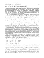
Fig. 1.5. A radiograph (“plain film”) of the chest. This has been acquired on a CR system using an X-ray generation set and europium-activated barium fluorohalide
plate read by a laser. Both PA (postero-anterior) and lateral views are shown. The views are named from the direction the X-rays pass through the patient and the
location of the detector: in the case of the PA film the X-ray tube is behind the patient and the detector plate in front so the X-rays pass from posterior to anterior.
(a)
(b)
An introduction to the technology of imaging thomas h. bryant and adam d. waldman
4
Conventional tomography
Simultaneously moving both the X-ray tube and the film about a pivot
point causes blurring of structures above and below the focal plane.
Objects within the focal plane show increased detail because of the
blurring of surrounding structures, providing an image of a slice of
the patient (Fig. 1.6). Movements of the X-ray tube and film can be
linear, elliptical, spiral, or hypocycloidal. With the advent of cross-
sectional imaging techniques such as CT and MRI, most imaging
departments now only use linear tomography, as part of an intra-
venous urogram (see below).
Contrast enhancing agents
To allow visualization of specific structures using X-rays, a number
of contrast agents have been used. A good contrast agent should
increase contrast resolution of organs under examination without poi-
soning or otherwise damaging the patient. The best contrast agents
for use with X-rays have a high atomic weight as these have a high
proportion of photoelectric absorption in the diagnostic X-ray range.
Unfortunately, most molecules that contain these atoms are very
toxic. Iodine (atomic weight 127) is the only element that has proved
satisfactory for general intravascular use; extensive research and
development has resulted in complex iodinated molecules that are
non-toxic, hypoallergenic and do not carry too great osmotic load. The
normal physiological turnover of iodine in the body is 0.0001 g per
day, while for typical imaging applications 15 g to 150 g or 150 000–1
500 000 times as much may be required. Barium sulphate (atomic
weight 137), and iodinated compounds are the only agents in regular
use as extravascular agents.
Barium studies
Barium is only used in a modern X-ray department for studies of the
gastrointestinal tract. These are usually based on a fluoroscopic
image intensifier on which a moving image can be seen. Studies can
be performed of the swallowing mechanism and esophagus (barium
swallow), the stomach and duodenum (barium meal), the small bowel
(small bowel follow through or small bowel enema) and the colon
(barium enema). Studies of the stomach and large bowel are usually
“double contrast” which allows better visualization of surface detail.
Air or carbon dioxide can be introduced into the large bowel and
gas-forming granules (usually a combination of calcium carbonate
and citric acid) can be swallowed for imaging the stomach, resulting
in a thin barium coating of the bowel mucosa (Fig. 1.7).
Intravenous urography
The kidneys rapidly excrete Iodinated contrast agents. Plain radi-
ographs taken from just a few seconds after a contrast injection into
a peripheral vein show the passage of contrast through the kidney,
into the ureters and to the bladder (Fig. 1.8).
Angiography
A specially shaped, thin catheter (tube) can be introduced into the
arterial or venous system and manipulated using fluoroscopy to
almost any blood vessel large enough to have been named. Contrast
introduced through these catheters by hand or mechanical injection
will be carried in the bloodstream and allows very detailed imaging
of the vascular system. The arterial system is usually accessed via
puncture of the femoral artery in the groin, although arteries of the
upper limb may occasionally be used. Digital subtraction angiography
(DSA) is most commonly performed – an initial (“mask”) image is
taken before the contrast agent is administered and is “subtracted”
from later images. This removes the image of the tissues, leaving
the contrast-filled structures. Any movement after the mask image
is taken destroys the subtracted image. Because angiography is
potentially hazardous, the balance between the potential benefit and
the risk of the procedure (damage to vessels and other structures,
bleeding) must be evaluated with particular care before undertaking
the procedure (Fig. 1.9).
Radiation dose
All ionizing radiation exposure is associated with a small risk. A small
proportion of the genetic mutations and cancers occurring in the pop-
ulation can be attributed to natural background radiation. Diagnostic
Fig. 1.7. Barium enema. Barium sulphate has been introduced into the large
bowel by a tube placed in the rectum and carbon dioxide gas is then used to
expand the bowel, leaving a thin coating of barium on its inside surface. X-ray
images are used to examine the lining of the bowel for abnormal growths and
other abnormalities.
X-ray tube
Focal plane
X-ray table
Film
Fig. 1.6. Conventional tomography. The X-ray tube and film move simultaneously
about a pivot point at the level of the focal plane, blurring structures outside
the focal plane, and emphasizing the structure of interest.
medical exposures (using X-rays or
␥
-rays, see Nuclear Medicine below)
are the largest source of man-made radiation exposure to the general
population and add about one-sixth to the population dose from back-
ground radiation. The dose is calculated as “effective dose,” which is
a weighted figure depending on the sensitivity of the body tissues
involved to radiation induced cancer or genetic effects. Typical doses
are given in Fig. 1.10. Children and the developing fetus are particu-
larly susceptible to radiation damage. As with all medical investiga-
tions and procedures, the relative risks and potential benefits must be
considered carefully, and the clinician directing the procedure (usually
the radiologist) is accountable in law for any radiation exposure.
Ultrasound
General principles
Ultrasound is sound of very high frequency. In most diagnostic appli-
cations frequencies between two million and twenty million cycles
per second are used, 100–1000 times higher than audible sound.
An introduction to the technology of imaging thomas h. bryant and adam d. waldman
5
Fig. 1.8. Intravenous urogram showing (a) standard view of the kidneys and upper part of the urinary collecting system and (b) linear tomogram of the intrarenal
collecting system. This blurs out the overlying structures, giving a clearer image of the collecting system and renal outline. An injection of 50 ml of iodine-
based contrast medium has been given and these radiographs have been obtained 10–15 minutes later after it has passed through the kidneys and into the
renal collecting system.
(a)
(a)
(b)
(b)
Fig. 1.9. Renal angiogram. (a) A catheter has been inserted through the right femoral artery into the aorta, (b) iodinated contrast medium has been injected through it,
and a rapid sequence of radiographs taken. Digital subtraction of the background shows the passage of contrast medium through the arteries supplying both kidneys.
Higher frequencies have shorter wavelengths, allowing greater spatial
resolution of structures being studied. An example of an ultrasound
machine is shown in Fig. 1.11.
Ultrasound transducers
Ultrasound is generated by piezoelectric materials, such as lead zir-
conate titanate (PZT). These have the property of changing in thick-
ness when a voltage is applied across them. When an electrical pulse
is applied, the piezoelectric crystal produces sound at its resonant
frequency. These crystals also generate a voltage when struck by an
ultrasound wave, so are also used as the receiver. A modern ultra-
sound probe contains an array of several hundred tiny piezoelectric
crystals with metal electrodes on their two surfaces, the sound lenses
and matching layers required to form the beam shape and electronics.
Piezoelectric crystals can also be found in the speakers inside in-ear
headsets, quartz watches, and camera auto-focus mechanisms.
Image formation
Ultrasound travels at near constant speed in soft tissues and this
allows the depth of reflectors to be calculated by measuring the delay
between transmission of the pulse and return of the echoes.
Attenuation
The tissues absorb ultrasound when the orderly vibration of the sound
wave becomes disordered in the presence of large molecules. When
this happens, sound energy is converted to heat energy. Absorption
depends on the molecular size, which correlates with viscosity of the
tissue, and with the frequency. Higher frequencies are more strongly
absorbed, so less depth of scanning comes with the improvement in
resolution that higher frequencies allow. Ultrasound energy is also
lost to the transducer if it is reflected or refracted away.
Reflection
Some of the ultrasound beam is reflected whenever it crosses an inter-
face where the transmission properties change. This is directly related
to the physical structure of the tissues on either side of the interface.
Tissue harmonics
Ultrasound is generally considered to be conducted in a linear fashion
with no change in the waveform of the pulse as it travels through the
tissues. In fact, the wave originating from the transducer becomes
distorted as the speed of sound conduction changes with the density
of the conducting materials allowing some parts of the wave to travel
faster than others. The wave comes to contain higher frequency
components, called harmonics, which are much weaker in the parts of
the sound beam away from the central echoes. Scanners can transmit
at one frequency, receive at a higher frequency and use filters to select
out the harmonics in the returning echoes, improving the image
resolution and increasing the contrast.
Image display
Gray-scale or B-Mode (B for brightness) is a two-dimensional real
time image formed by sweeping the beam through the tissue. The
echogenicity of the reflectors is displayed as shades of gray and is the
main mode used for ultrasound imaging (Fig. 1.12). Modern ultrasound
machines operate at a sufficient speed to produce real-time images
of moving patient tissue such as the heart in echocardiography and
the moving fetus.
Doppler ultrasound
If a sound wave reflects from a moving target, there is a change in the
frequency of the returning sound wave proportional to the velocity
of the reflecting target. This is known as the Doppler effect and the
changes in frequency can be used to calculate the velocity of the
moving target usually flowing blood. The Doppler signal is within
the audible range, so can be heard by sending the signal to a loud-
speaker. Most commonly used in clinical practice is color flow imaging
(color Doppler) where flow information is shown as an overlay on the
gray-scale image with the color and shading indicating the direction
An introduction to the technology of imaging thomas h. bryant and adam d. waldman
6
Fig. 1.11. A diagnostic ultrasound machine.
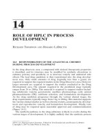
Procedure Typical effective Equivalent Equivalent period of
dose (mSv) number natural background
of chest X-rays radiation
Limbs and joints Ͻ0.01 Ͻ0.5 Ͻ1.5 days
Chest 0.02 1 3 days
Lumbar spine 1.3657months
Pelvis 0.7354months
Abdomen 1.0506months
IVU 2.5 125 14 months
Barium enema 7 350 3.2 years
CT head 2.3 115 1 year
CT chest 8 400 3.6 years
CT abdomen 10 500 4.5 years
or pelvis
Bone scan 4 200 1.8 years
PET head (FDG) 5 250 2.3 years
Fig. 1.10. Typical effective doses for some of the commonly performed Imaging
investigations. The typical United Kingdom background radiation dose is
2.2 mSv/year (ranges from 1.5 to 7.5 mSv/year depending on geographical
location). It has been estimated that the additional lifetime risk of a fatal cancer
from an abdominal CT scan could be as much as 1 in 2000 (although the overall
lifetime risk of cancer for the whole population is 1 in 3).