Applied Radiological Anatomy for Medical Students Applied - part 3 doc
Bạn đang xem bản rút gọn của tài liệu. Xem và tải ngay bản đầy đủ của tài liệu tại đây (662.4 KB, 18 trang )
will not be seen on chest radiograph. However, because of the supe-
rior contrast resolution, the normal pleura may be visualized on CT
images (Fig. 3.4).
The trachea is a vertically orientated tube (measuring approxi-
mately 13 cm in length), which commences below the cricoid cartilage
and extends to the approximate level of the sternal angle where is
bifurcates. In cross-section the outline of the trachea may vary from
being oval to a D-shape, depending on the phase of breathing cycle.
Anteriorly and laterally, the trachea is bounded by hoops of hyaline
cartilage but posteriorly there is a relatively pliable membrane. On a
chest radiograph, the trachea is seen as a tubular region of lucency in
the midline, as it passes through the thoracic inlet (Fig. 3.5). At the
level of the aortic arch, there may be slight (but entirely normal) devi-
ation of the trachea to the right. At the level of the carina, the trachea
divides into right and left main bronchi; the former is shorter, wider
and more vertically oriented than its counterpart on the left (Fig. 3.6).
Each main bronchus gives rise to lobar bronchi, which divide to
supply the bronchopulmonary segments in each lobe. Individual bron-
chopulmonary segments are not readily identified (on chest radiogra-
phy or CT) but it is worth revising the anatomy because segmental
airways and arteries can be seen particularly well on CT images and
such information may be important to clinicians. On the right, there
are ten segments (three in the upper lobe, two in the middle and five
in the lower lobe), whereas on the left there are nine (three in upper
lobe, two in the lingula and four in the lower lobe (Fig. 3.7).
The mediastinum
For descriptive purposes, the mediastinum has always been thought
of in terms of its arbitrary compartments. Thus, the superior medi-
astinum is considered to lie above a horizontal line drawn from the
lower border of the manubrium, the sternal angle or angle of Louis,
to the lower border of T4 and below the thoracic inlet (Fig. 3.8). The
inferior compartment, lying below this imaginary line (and above the
hemidiaphragm) is further subdivided: the anterior mediastinum lies
in front of the pericardium and root of the aorta. The middle medis-
tinum comprises the heart and pericardium together with hilar struc-
tures, whereas the posterior mediastinum lies between the posterior
aspect of the pericardium and the spine. Whilst the above division is
entirely arbitrary, the validity of remembering such a scheme is that
the differential diagnosis of mediastinal masses is refined by consider-
ing the localization of a mass in a particulary mediastinal compart-
ment. The main contents of the different mediastinal compartments
are listed in Table 3.1. Some of the important components of the medi-
astinum are discussed below:
The esophagus
The esophagus extends from the pharynx (opposite the C6 vertebral
body) through the diaphragm (at the level of T10) to the gastro-
esophageal junction and measures approximately 25 cm in length.
In its intrathoracic course the esophagus is a predominantly a left-
sided structure, a feature which is readily appreciated on CT images
(Fig. 3.9). By contrast, the esophagus is normally not visible on a
standard PA radiograph, and radiographic examination requires
the patient to drink a radioopaque liquid (i.e., a barium
suspension).
The thymus
The thymus is a bilobed structure, which is posititoned in the space
between the great vessels (arising from the aorta) and the anterior
The chest wall and ribs jonathan d. berry and sujal r. desai
25
Fig. 3.4. Targeted view of the left lower zone on CT showing normal thin pleura
(arrow).
AA
AA
Fig. 3.5. PA chest
showing the
characteristic tubular
lucency of the trachea
(arrowheads). The
normal and minimal
deviation of the trachea
to the right is noted at
the level of the aortic
arch (AA).
*
Fig. 3.6. Targeted and
magnified view of the
tracheal carina (asterisk).
The right main bronchus
(thin arrows) is shorther
and more vertically
orientated than the left
(thick arrows).
The chest wall and ribs jonathan d. berry and sujal r. desai
26
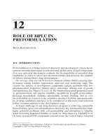
Fig. 3.7. Schematic diagram illustrating the segmental anatomy of the bronchial tree (reproduced with
permission from Applied Radiological Anatomy, 1st edn, Chapter 6, The chest, p. 129, Fig. 11(f), ed. P.
Butler; Cambridge University Press).
Right upper
lobe bronchus
Right apical
bronchus
Right posterior
bronchus
Right anterior
bronchus
Right middle
lobe bronchus
Lateral bronchus of
right middle lobe
Medial bronchus of
right middle lobe
Right lateral
basal brochus
Right posterior
basal bronchus
Right anterior
basal bronchus
Medial basal
(cardiac)
bronchus
Apical
bronchus
of lower
lobe
Lingular
brochus
Left lateral
basal bronchus
Left anterior
basal bronchus
Inferior lingular
bronchus
Superior lingular
bronchus
Left anterior
bronchus
Left posterior
bronchus
Left apical bronchus
Apicoposterior
bronchus
Left upper
lobe bronchus
Left posterior
basal bronchus
R
LLL
BI
RUL
3
2
4
ML
RLL
5
6
7
8
9
10
4
17
18
19
20
17
16
15
14
LUL
13
12
11
L
1
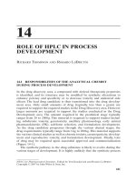
Fig. 3.8. Lateral
radiograph
demonstrating the
anterior (A), middle (M),
posterior (P) and
superior (S) mediastinal
compartments.
table 3. 1. American Thoracic Society definitions of regional nodal
stations
X Supraclavicular nodes
2R Right upper paratracheal nodes: nodes to the right of the midline of
the trachea, between the intersection of the caudal margin of the
innominate artery with the trachea and the apex of the lung
2L Left upper paratracheal nodes: nodes to the left of the midline of the
trachea, between the top of the aortic arch and the apex of the lung
4R Right lower paratracheal nodes: nodes to the right of the midline of
the trachea, between the cephalic border of the azygos vein and the
intersection of the caudal margin of the brachiocephalic artery with
the right side of the trachea
4L Left lower paratracheal nodes: nodes to the left of the midline of the
trachea, between the top of the aortic arch and the level of the carina,
medial to the ligamentum arteriosum
5 Aortopulmonary nodes: subaortic and paraaortic nodes, lateral to the
ligamentum arteriosum or the aorta or left pulmonary artery,
proximal to the first branch of the left pulmonary artery
6 Anterior mediastinal nodes: nodes anterior to the ascending aorta or
the innominate artery
7 Subcarinal nodes: nodes arising caudal to the carina of the trachea but
not associated with the lower lobe bronchi or arteries within the lung
8 Paraesophageal nodes: nodes dorsal to the posterior wall of the
trachea and to the right or left of the midline of the esophagus
9 Right or left pulmonary ligament nodes: nodes within the right or left
pulmonary ligament
10R Right tracheobronchial nodes: nodes to the right of the midline of the
trachea, from the level of the cephalic border of the azygos vein to the
origin of the right upper lobe bronchus
10L Left tracheobronchial nodes: nodes to the left of the midline of the
trachea, between the carina and the left upper lobe bronchus, medial
to the ligamentum arteriosum
11 Intrapulmonary nodes: nodes removed in the right or left lung specimen,
plus those distal to the main-stem bronchi or secondary carina
From Glazer et al. (1985).
chest wall. The volume of the thymus normally changes with age: in
the newborn, for example, the thymus may occupy the entire volume
of the mediastinum anterior to the great vessels (Fig. 3.10). With age,
the thymus initially hypertrophies, but after puberty there is progres-
sive atrophy, such that in normal adults, the normal thymus is barely
discernible.
The hilum
The hilum can be considered to be the region at which pulmonary
vessels and airways enter or exit the lungs. The main components of
each hilum are the pulmonary artery, bronchus, veins, and lymph
nodes. On a frontal radiograph, the right hilum may be identified as a
broad V-shaped structure; the left hilum is often more difficult to
identify confidently (Fig. 3.11). A useful landmark for the radiologist,
primitive aortae; with subsequent septation and coiling, the character-
istic asymmetric configuration of the adult heart is attained. The peri-
cardium, which like the pleura is a two-layered membrane, encases
the heart; the inner (or visceral) pericardium is applied directly to the
myocardium except for a region that reflects around the pulmonary
veins. The outer (parietal) pericardium is continuous with the adventi-
tial fibrous covering of the great vessels. Inferiorly, the parietal peri-
cardium blends with the central tendon of the diaphragm. As with the
pleura, the potential space between the visceral and parietal peri-
cardium (the pericardial sac) is not normally visible on plain radi-
ographs. Again, because of the superior contrast resolution of CT, the
normal pericardial lining may be identified on axial images.
In normal subjects there are four cardiac chambers (the paired atria
and ventricles). Deoxygenated blood is normally delivered to the right
atrium via the superior vena cava (from the upper limbs, thorax, via the
azygos sytem, and the head and neck), the inferior vena cava (from the
lower limbs and abdomen), and the coronary sinus (from the
myocardium). The right atrium is separated from its counterpart on the
left by the inter-atrial septum which, with the changes in pressure that
occur at or soon after birth, normally seals; a depression in the intera-
trial septum marks the site of the foramen ovale in the fetal heart. The
right atrium is a “border-forming” structure on a PA radiograph that is
immediately adjacent to the medial segment of the right middle lobe, a
feature that is readily appreciated on CT images (Fig. 3.12). The right
ventricle communicates with the atrium via the tricuspid valve.
Deoxygenated blood leaves the right ventricle through the pulmonary
valve and enters the pulmonary arterial tree. Because the right ventricle
is an anterior chamber, it does not form a border on the standard PA
radiograph but the outline of the chamber is visible on a lateral radi-
ograph. The left atrium is a smooth-walled chamber and is posteriorly
positioned. Oxygenated blood enters the atrium from the paired pul-
monary veins on each side and exits via the mitral valve to the left ven-
tricle from where blood is delivered into the systemic circulation. As on
the right, there is a left atrial appendage (sometimes referred to as the
auricular appendage), which may be the only part of the normal atrium
that is seen on the frontal radiograph; conversely, the wall of the left
atrium is easily identified on a lateral radiograph.
The left ventricle is the most muscular cardiac chamber and is a
roughly cone-shaped structure whose axis is oriented along the left
anterior oblique plane. On a frontal chest radiograph, the left ventricle
accounts for most of the left heart border. It is worth mentioning at this
point that the widest transverse diameter of the heart (extending from
the right (formed by the right atrium) to the left margin) is an impor-
tant measurement on the frontal radiograph: as a general rule, the
transverse diameter should be less than half the maximal diameter of
the chest (this measurement is called the cardiothoracic ratio).
The chest wall and ribs jonathan d. berry and sujal r. desai
27
*
Fig. 3.9. Axial CT image on soft tissue window settings at the level of the great
vessels. The oesophagus (arrow) can seen lying just to the left of the midline
and posterior to the trachea (asterisk).
Fig. 3.10. CT of the
normal thymus in an
infant. There is a well-
defined mass (thin
arrows) in the superior
mediastinum. Note how
the mass conforms to
the outline of some the
major vessels (the aorta
[thick arrow] and
superior vena cava
(arrowhead)) in the
mediastinum, and does
not displace them.
Fig. 3.11. Targeted and magnified view from PA chest radiograph clearly shows
the hilar vessels. The right and left hilar points (where the upper lober veins
apparently “cross” the lower lobe artery) are indicated (arrows).
RA
Fig. 3.12. Axial CT image
on lung parenchymal
window settings
showing the relationship
of the middle lobe (lying
anterior to the horizontal
fissure [arrows]),
particularly its medial
segment and the right
atrium (RA).
on the PA radiograph, is the so-called “hilar point” which, whilst not
being a true anatomical structure, is the apparent region where the
upper lobe pulmonary veins meet the lower pulmonary artery. In
normal subjects, the hilar point is sited roughly between the apex and
the base of the hemithorax: in some patients, significant elevation or
depression of the hilar point will be the only clue to the presence of
volume loss in the lungs.
The heart
In the embryo, the heart is one of the earliest organs to develop,
following fusion of two parallel tubular structures known as the
Oxygenated blood normally enters the ventricle from the left
atrium via the mitral valve and is pumped into the systemic circula-
tion through the aortic valve. Just above the aortic valve there are
three focal dilatations, called the sinuses of Valsalva. The right coro-
nary artery originates from the anterior sinus, whilst the left posterior
sinus gives rise to the left coronary artery; the coronary circulation is
described as either right (the most common arrangement) or left
dominant depending on which vessel supplies the posterior diaphrag-
matic region of the interventricular septum and diaphragmatic
surface of the left ventricle. The right coronary artery usually runs
forward between the pulmonary trunk and right auricle. As it
descends in the atrioventricular groove, branches arise to supply the
right atrium and ventricle. At the inferior border of the heart, it con-
tinues and ultimately unites with the left coronary artery. The larger
left coronary artery descends between the pulmonary trunk and left
auricle, and runs in the left atrioventricular groove for about 1 cm
before dividing into the left anterior descending (interventricular)
artery and the circumflex arteries. In around one-third of normal sub-
jects, the left coronary artery will trifurcate and in such cases there is
a “ramus medianus” or “intermediate” artery between the left ante-
rior descending and circumflex arteries supplying the anterior left
ventricular wall. The venous drainage of the heart is via the coronary
sinus (which enters the right atrium) and receives four main tribu-
taries: the great cardiac vein, middle cardiac vein, small cardiac vein,
and left posterior ventricular vein. A smaller proportion of the venous
drainage is directly into the right atrium via the anterior cardiac veins
that enter the anterior surface of the right atrium. As might be imag-
ined, the normal cardiac circulation is not seen on standard radi-
ographic examinations. However, the injection of intravenous contrast
via a coronary artery catheter (inserted retrogradely via the femoral
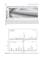
artery) will render the vessels visible (Fig. 3.13). An alternative
approach (which has only become possible since the advent of “fast”
CT scanning machines) is for the cardiac circulation to be imaged fol-
lowing a peripheral injection of contrast. More recently, there has
been considerable interest in the imaging of the heart and its circula-
tion using magnetic resonance imaging.
The aorta
The intrathoracic aorta can conveniently be considered in four parts:
the root, the ascending aorta, the arch, and the descending aorta.
The root comprising the initial few centimeters, is invested by
pericardium and includes three focal dilatations, the sinuses of
Valsalva (described above) above the aortic valve leaflets. The ascend-
ing aorta continues upward and to the right for approximately 5 cm to
the level of the sternal angle. The arch lies inferior to the manubrium
sterni and is directed upward, inferiorly, and to the left. The arch ini-
tally lies anterior to the trachea and esophagus, but then extends to
the bifurcation of the pulmonary trunk. The three important branches
of the aortic arch are the brachiocephalic artery, the left common
carotid artery, and the left subclavian artery, all of which are readily
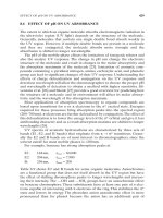
visible on angiographic studies and CT (Fig. 3.14). Variations to this
normal pattern of branching occur in approximately one-third of sub-
jects; the most common variant is that in which the left common
carotid arises from the brachiocephalic artery.
By convention, the descending aorta begins at the point of attach-
ment of the ligamentum arteriosum to the left pulmonary artery
(roughly at the level of T4). The descending aorta passes downward in
the posterior mediastinum on the left to the level of T12, where it
passes through the diaphragm and into the abdomen. Within the
thorax, the descending aorta gives rise to the intercostal, subcostal
arteries, bronchial, esophageal, spinal, and superior phrenic arteries.
Pulmonary arteries
At its origin from the right ventricle, the pulmonary conus or trunk is
invested by a pericardial reflection. The main divisions of trunk are
the left and right pulmonary arteries. The right pulmonary artery
passes in front of the right main bronchus and behind the ascending
aorta. Anteriorly, the right superior pulmonary vein crosses the right
The chest wall and ribs jonathan d. berry and sujal r. desai
28
Catheter
Atrial branch
Inferior L
V
free wall
branches
Posterior descending artery
RV free
wall branch
Catheter
Conus branch
RV free wall branches
Superimposed posterior
descending and
LV free wall branches
Atrial
branch
AA DA
B
RS
RCC
LCC
LSC
RCC
RS
LCC
LSC
(a) (b)
Fig. 3.13 (a), (b). Coronary angiogram demonstrating the left and right coronary arteries (reproduced with permission from Applied Radiological Anatomy, 1st edn,
Chapter 7, The heart and great vessels, p. 165, Figs. 24 and 25; ed. P. Butler, Cambridge University Press).
Fig. 3.14. Digital
subtraction angiogram
showing the ascending
(AA) and descending
(DA) aorta. Note that the
brachiocephalic artery
(B) bifurcates into the
right subclavian (RS) and
right common carotid
(RCC) arteries; the left
common carotid (LCC)
and left subclavian (LSC)
also arise from the
aortic arch.
main artery (Fig. 3.15). At the hilum, the artery divides into the upper
and lower divisions, from which the lobar and segmental branches
orginate; It is important to remember that arterial branching (unlike
the pulmonary veins) closely follows the branching of the airways.
The left main pulmonary artery passes posteriorly from the pul-
monary trunk and then arches over the left main bronchus. As with
the coronary arteries, the pulmonary circulation is visualized opti-
mally after the injection of intravenous contrast, as in conventional
pulmonary angiography (a technique seldom performed in modern
radiology departments) or on CT images. The venous drainage of the
lungs is via the left and right pulmonary veins, two on each side,
which enter the left atrium beneath the level of the pulmonary arter-
ies. Occasionally, the veins can be seen to unite prior to their entry
into the left atrium.
It should be remembered that, in addition to the main pulmonary
arterial supply, there is a bronchial circulation originating from the
systemic circulation. The most common arrangement is of a single
right bronchial artery (usually arising from the third posterior inter-
costal) and two left bronchial arteries (originating from the descend-
ing thoracic aorta). However, there is considerable normal variation.
There are two groups of bronchial veins: the deep veins taking blood
from the lung parenchyma and draining into the pulmonary veins.
The superficial bronchial veins receive blood from the extrapul-
monary bronchi, visceral pleura, and hilar lymph nodes, both drain-
ing into the pulmonary veins. The bronchial vessels, although small,
are of great clinical importance. They maintain perfusion of the
lung after a pulmonary embolism so that, if the patient recovers,
the affected lung returns to normal.
The thoracic duct
The thoracic duct is the main channel by which lymph is returned to
the circulation. The thoracic duct begins within the abdomen as a
dilated sac known as the cistrna chyla and ascends through the
diaphragm on the right of the aorta. At the level of the sixth thoracic
vertebral body, the thoracic duct crosses to the left of the spine and
passes upwards to arch over the subclavian artery. The duct drains
lymph into a large central vein, which is close to the union of the left
internal jugular and subclavian veins. The diameter of the thoracic
duct may vary between 2 and 8 mm and, although usually single, mul-
tiple channels may exist. In normal subjects, the thoracic duct is col-
lapsed and, as such, cannot be visualized on imaging studies. A
variation on the normal is for a right-sided lymphatic duct, which
drains lymph from the right side of the thorax, the right upper limb,
and right head and neck into the right brachiocephalic vein.
The thoracic cage
Ribs, sternum and vertebrae
The thorax is roughly cylindrical in shape and shielded by the ribs,
thoracic vertebrae, and the sternum. All 12 pairs of ribs are attached
posteriorly to their respective vertebral bodies. In addition, the upper
seven pairs attach anteriorly to the sternum via individual costal carti-
lages. The eighth, ninth and tenth ribs effectively are attached to each
other and also the seventh rib by means of a “common” costal carti-
lage. With age, the costal cartilages may calcify and are then readily
visible on a frontal radiograph. The two lowermost ribs (the 11th and
12th) are described as “floating” since they have no anterior attach-
ment. An interesting variation to the normal arrangement (occuring
in around 6% of the population) is the so-called “cervical” rib, which
articulates with a cervical, instead of a throracic vertebral body
(Fig. 3.16). Cervical ribs may be uni- or bilateral. Occasionally, there
will simply be a fibrous band but, when calcified, the appearance of a
“true rib” will be seen. Some cervical ribs are symptomatic because of
the potential for compression of the subclavian artery and first tho-
racic nerve root.
The sternum can be considered to comprise three components: the
manubrium sterni, the body of the sternum, and the xiphoid process
(or xiphisternum). The manubrium is the uppermost and widest
portion, which articulates laterally with the clavicles and also the first
and upper part of the second costal cartilages; inferiorly, the
manubrium articulates with the body of the sternum. On a conven-
tional frontal chest radiograph, the bulk of the manubrium is gener-
ally not visible. However, the articulation of the manubrium with the
clavicles (the manubrio-clavicular joint) can be seen. By contrast, on a
lateral radiograph the manubrium can be clearly identified. The body
of the sternum is a roughly rectangular structure which has a notched
lateral margin, where it articulates with the costal cartilages of the
third to seventh ribs. The xiphoid is the most inferior portion of the
sternum and prinicipally consists of hyaline cartilage that may
become ossified in later life.
The thoracic vertebrae provide structural support to the thorax in
both the axial (vertical) and, through the attachment with ribs and
muscles, the coronal and sagittal planes. Whilst individual vertebrae
are rigid, their articulations mean there is considerable potential
mobility in terms of flexion, extension, and rotational movements
over the length of the twelve vertebrae. There is a progressive increase
in the height of thoracic vertebrae bodies from T1 to T12 and these
vertebrae can be distinguished by the presence of lateral facets, which
articulate with the heads of the ribs. Facet joints for articulation with
the tubercles of the ribs are also present on the transverse processes
of T1 to T10. Furthermore, when viewed in the sagittal plane, each
The chest wall and ribs jonathan d. berry and sujal r. desai
29
AAo
DAo
PT
RtPA
LtPA
*
PT
AAo
RtPA
DAo
LtPA
Fig. 3.15
.
CT image just
below the level of the
tracheal carina. The right
main pulmonary artery
(RtPA) passes in front of
the right main bronchus
(arrow). The left
pulmonary artery arches
over the left main
bronchus (asterisk).
AAo ϭ ascending aorta;
PT ϭ pulmonary trunk;
LtPA ϭ left basal
pulmonary artery.
Fig. 3.16. Targeted view
from a PA chest
radiograph
demonstrating a
unilateral left sided
calcified cervical rib
(arrows).
vertebrae can be seen to possess a long spinous process; with the
exception of T1 (whose spinous process is almost horizontal), the
spinous processes all point downward.
Initial analysis of the thoracic vertebrae is still best done with a suit-
ably penetrated plane film. However, in the presence of complex
trauma or where the contents of the spinal canal need to be visual-
ized, CT and MRI are being employed increasingly.
Muscles of the chest wall
There is a complex arrangement of muscles around the chest which,
in addition to the vital act of breating, help to maintain stability.
Outermost and anteriorly are the pectoralis (major and minor)
muscles; serratus anterior is situated laterally, and posterolaterally are
the muscles of the shoulder girdle. Posteriorly and adjacent to the ver-
tebrae are erector spinae and trapezius. These muscle groups are
readily depicted on axial (CT and MRI) images (Fig. 3.17). The deeper
muscles of the chest include the intercostal muscles (external, inter-
nal, and innermost), which are situated between the ribs. Elsewhere,
the subcostal muscles span several ribs and further muscles attach the
ribs to the sternum and vertebrae. All these muscles may be visualized
accurately with MR.
Each intercostal space is supplied by a single large posterior inter-
costal artery and paired anterior intercostal arteries. Incidentally, each
posterior intercostal artery also gives off a spinal branch, which sup-
plies the vertebrae and spinal cord. The venous drainage is via the
posterior intercostal veins running backward to drain into the azygos
(or hemi-azygos) and the anterior intercostal veins into the internal
thoracic and musculophrenic veins.
Nerve supply of the chest wall
The innervation of the chest wall is via 12 paired thoracic nerves.
The 11 pairs of intercostal nerves run between the ribs while the
twelfth pair (the subcostal nerves) runs below the twelfth rib in
the anterior abdominal wall. The intercostal nerves are the anterior
rami of the first 11 thoracic spinal nerves, which enter the inter-
costal space between the parietal pleura and posterior intercostal
membrane to run in the subcostal groove of the corresponding
ribs and below the intercostal artery and vein. It is for this reason
that, whenever possible, needle aspiration or pleural drainage should
be performed by entering the pleural space immediately above.
In addition to the peripheral nervous system, the sympathetic chain
is also found within the thorax. There are either 11 or 12 sympathetic
The chest wall and ribs jonathan d. berry and sujal r. desai
30
ganglia within the thorax. The first ganglia is frequently fused with
the inferior cervical ganglia to form the cervicothoracic or “stellate”
ganglia. The remaining ganglia are simply numbered so that they cor-
respond to the adjacent segmental structures. A number of plexi are
formed through the fusion of different ganglia, for example, the
cardiac plexus and aortic plexus.
The diaphragm
The diaphragm is the domed structure, which serves to separate the
contents of the thorax from those of the abdomen and plays a vital
role in breathing. The components of the diaphragm are a peripheral
muscular portion and a central tendon. The diaphragm is fixed to the
chest wall at three main points: the vertebral attachment (via the
crura which extend down to the level of the lumbar vertebrae), the
costal component (comprising slips of muscle attached to the the deep
part of the six lowermost ribs), and finally the sternal component
(consisting of slips of muscle arising from the posterior aspect of the
xiphoid process). At three points, roughly in the midline, the central
tendon transmits (and is pierced) by the esophagus, descending aorta,
and inferior vena cava.
The normal diapragm is easily visualized on both frontal and lateral
radiographs as a smooth but curved structure. Laterally, on the frontal
radiograph, the diaphragm appears to make contact with the chest
wall. At the apparent point of contact (called the costophrenic recess)
the angle subtended to the chest wall is acute and well defined. This
is of practical value since even small collections of fluid (pleural
effusions) will lead to a blunting of the costophrenic recess.
*
Fig. 3.17. Coronal
magnetic resonance
image of the posterior
aspect of the thorax at
the level of the
acromion process of the
scapula (arrow) showing
the erector spinae
muscles (asterisk).
Breast cancer is the commonest malignancy in women in Europe and
the United States. In recent years, physicians and the media have
encouraged women to practice self-examination, to have regular evalua-
tion by a medical practitioner, and to participate in breast screening
programs. This has resulted in the general population developing a
heightened awareness of breast cancer and in turn presenting to the
general practitioner with a variety of breast complaints. In order to
evaluate properly such symptoms, there must be an understanding
of the normal breast. This chapter serves to describe normal breast
anatomy and the role of imaging techniques used to evaluate the
breast.
Embryology
During the fourth gestational week, paired ectodermal thickenings
called mammary ridges (milk lines) develop along the ventral surface
of the embryo from the base of the forelimb buds to the hindlimb
buds. In the human, only the mammary ridges at the fourth inter-
costal space will proliferate and form the primary mammary bud,
which will branch further into the secondary buds, develop lumina
and coalesce to form lactiferous ducts. By term, there are 15–20 lobes
of glandular tissue, each with a lactiferous duct. The lactiferous ducts
open onto the areola, which develops from the ectodermal layer. The
supporting fibrous connective tissue, Cooper’s ligaments, and fat in
the breast develop from surrounding mesoderm.
At birth, the mammary glands are identical in males and females and
remain quiescent until puberty, when ductal growth occurs in females
under the influence of estrogens, growth hormones and prolactin.
When pregnancy occurs, the glands complete their differentiation by
eventually forming secretory alveoli. After the menopause, decreased
hormone levels lead to a senescent phase with involution of the glandu-
lar component and replacement with connective tissue and fat.
Congenital breast malformations fall into two categories: the pres-
ence of supernumerary tissue, or the underdevelopment of breast
tissue. If the milk line fails to involute, it results in supernumerary
breast tissue. The commonest form, found in 2–5% of the population,
is polythelia, which is the presence of two or more nipples along the
chest wall in the plane of the embryonic milk line. The absence or
underdevelopment of breast tissue is less common. The severity
ranges from amastia, the complete absence of glandular tissue, nipple
and areola, to hypoplasia, the presence of rudimentary breasts.
Breast anatomy
The adult breast lies on the anterior chest wall between the second
rib above and the sixth rib inferiorly, and from the sternal edge medi-
ally to the mid-axillary line laterally. Breast tissue also projects into
the axilla as the axillary tail of Spence. The breasts lie on the pectoral
fascia, covering the pectoralis major and minor muscles medially and
serratus anterior and external oblique muscles laterally. The breasts
are contained within a fascial sac, which forms when the superficial
pectoral fascia splits into anterior (superficial) and posterior (deep)
layers. The suspensory Cooper’s ligaments are projections of the
superficial fascia that run through the breast tissue and connect to
subcutaneous tissues and skin.
The nipple is found centrally on each breast and has abundant
sensory nerve endings. The lactiferous ducts each open separately
on the nipple. Surrounding the nipple is the areola, which is pigmented
and measures 15–60 mm. Near the periphery of the areola are eleva-
tions (tubercles of Morgagni) formed by the openings of modified seba-
ceous glands, whose secretion protect the nipple during breastfeeding.
The human breast contains 15–20 lobes. Each of these lobes has
a major duct, which connects to, and opens on, the nipple. Each lobe
consists of numerous lobules, which in turn are made of numerous
acini (or ductules). This forms the basis of the terminal ductal lobular
unit (TDLU), which is a histological descriptive term. The TDLU is an
important structure, as it is postulated that most cancers arise in the
terminal duct, either inside or just proximal to the lobule. The ducts
are named according to their position along the branching structure.
The acini drain into the intralobular ducts which drain into the extralob-
ular ducts and eventually into the main duct, which opens on the
nipple. The acini and ducts structures form the glandular breast
parenchyma, which is surrounded by fatty tissue and fibrous connec-
tive tissue, which forms the stroma.
The glandular breast parenchyma predominates in the anterior
third and upper quadrant of the breast. Between the glandular
31
Section 2 The thorax
Chapter 4 The breast
STELLA COMITIS
Applied Radiological Anatomy for Medical Students. Paul Butler, Adam Mitchell, and Harold Ellis (eds.) Published by Cambridge University Press. © P. Butler,
A. Mitchell, and H. Ellis 2007.
parenchyma and the pectoral muscle, there is predominantly fatty
tissue named the retroglandular tissue.
The relative amounts of glandular breast tissue and stroma alter over
the normal lifespan. Younger women have more glandular breast tissue
and, with increasing age, this is replaced with fibrofatty tissue, particu-
larly after the menopause. Women who take hormone replacement
therapy preserve the glandular breast tissue for a longer period. With
pregnancy, the number of acini is increased and this persists in the lac-
tation period. After pregnancy, the acini decrease in number and the
breast will be less dense than prior to pregnancy. There is, however,
great variation in the composition of breast tissue with some women
having fatty breasts throughout their lives and others with extremely
dense glandular and fibrous tissue.
Arterial supply
The arterial supply of the breast is derived from branches of the inter-
nal thoracic artery, lateral thoracic artery, and posterior intercostal
arteries. Venous drainage is primarily into the axillary vein but also
into the internal thoracic vein, subclavian vein, and azygos vein.
Nerve supply
Innervation of the breasts is primarily via the anterior and lateral
cutaneous branches of the upper six thoracic intercostal nerves.
Lymphatics
Understanding the lymphatic drainage of the breast is vital because of
its importance in the spread of malignant disease. The majority (97%)
of the lymph from the breast drains to axillary nodes, and approxi-
mately 3% drains to the internal thoracic nodes. For surgical purposes,
to plan the removal of pathological nodes, the axilla is divided into
three arbitrary levels. Level I nodes (low axilla) lie lateral to the lateral
border of the pectoralis minor muscle, level II nodes (mid axilla) lie
behind the muscle, and the level III nodes (apical axilla) are located
medial to the medial border of the pectoralis minor muscle.
The concept of a sentinel node, which is defined as the first node that
drains a cancer, was first described in relation to melanoma and subse-
quently adapted to breast tumors. A blue dye (or more recently in
combination with a radiolabeled colloid), is injected into the tumor
and the identification of this dye in the sentinel node will predict the
status of the remaining nodes (95% accuracy).
Normal axillary lymph nodes can be demonstrated on both mam-
mography and ultrasound. On mammography, nodes are oval struc-
tures with a lucent centre due to the fatty hilum and should measure
less than 2 cm. On ultrasound, normal nodes are oval with a hypoe-
choic rim and a bright center (Figs. 4.1, 4.2). Arterial and venous
supply is seen entering and leaving from the hilum, which can be
notched with the result that the lymph node will have a bean-shape.
Imaging
Mammography allows excellent characterization of breast tissue.
Special mammography units use low dose radiation to image the
breast tissue. Mammography is most suitable for women over the age
of 40, as at a younger age the glandular tissue is very dense and differ-
entiation of the tissues is difficult. Mammography can be performed
with the patient seated or standing. To maximize the tissue imaged,
the breast needs to be pulled away from the chest wall and com-
pressed. Compression creates a uniform thickness through which the
X-ray beam penetrates so that a uniform exposure can be obtained.
Compression also reduces motion artifact by holding the breast still
and by separating overlapping structures.
Two views of each breast are obtained in the first instance: a medio-
lateral-oblique (MLO) view and a cranio-caudal (CC) view. The MLO
view allows the breast to be viewed in profile, ideally from high in the
axilla to the inframammary fold (Fig. 4.3). In the CC projection the
breast is viewed as if looking from above the breast downwards. In an
adequate CC projection, the nipple is seen in profile and the retroglan-
dular fat should be visible. Generally, more tissue can be projected on
The breast stella comitis
32
Normal axillary
lymph nodes
Glandular tissue
Fatty tissue
Bright fatty hilum
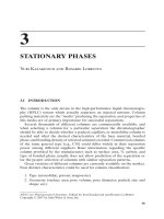
Fig. 4.1. Mammogram in the mediolateral oblique (MLO) projection,
demonstrates normal sized axillary lymph nodes with notched hilum. Note
the normal calcified vessels bilaterally.
Fig. 4.2. Ultrasound of the axillary tail demonstrating a normal axillary lymph
node with central fatty hilum.
Pectoralis major muscle
Retroglandular fat
Glandular tissue
Nipple in profile
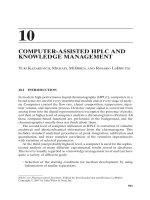
Fig. 4.3. Mammogram in the mediolateral oblique (MLO) projection. The
pectoralis major muscle projects to the level of the nipple and the retroareolar
fat is well seen. The nipple is visualized in profile.
The breast stella comitis
33
Calcified cyst
Retroglandular fat tissue
Glandular tissue
Pectoralis major muscle
Fig. 4.4. Mammogram in the cranio-caudal (CC) projection. The retroglandular
tissue is seen but the pectoral muscle is only visible in 30–40% of CC projection
mammograms.
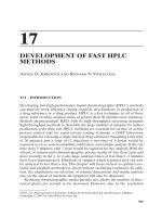
(a) (b)
Fig. 4.5. Wolfe
classification of breast
parenchymal patterns
(a) N1 predominantly
fatty tissue (b) P1 is less
than 25% nodular tissue
(c) P2 is greater than
25% nodular tissue
(d) DY pattern is
uniformly extremely
dense breast tissue.
the MLO projection than on the CC projection because of the slope
and curve of the chest wall. The pectoralis major muscle is visualized
in only 30–40% of women on a normal CC view (Fig. 4.4).
Normal mammographic patterns
Patterns of normal breast parenchyma vary greatly (Fig. 4.5). The most
widely accepted classification of breast patterns is that of Wolfe,
which consists of four groups.
Pattern type Description
N1 Predominantly fatty parenchyma
P115–25% nodular densities
P2 Ͼ35% nodular densities
DY pattern Extreme nodularity and density
(c)
(d)
The breast stella comitis
34
Skin
Fat lobule
Pectoralis
major muscle
Rib
Chest cavity
Nipple
Glandular tissue
Fat
Pectoralis major
muscle
Prominent ducts
Leading to nipple
system
Fat lobule
Fibrous septa
Pectoralis major
muscle
Rib casting
posterior
shadow due to
calcification
Pleura with
chest cavity
below
Fig. 4.7. Ultrasound axial image of axillary tail demonstrates normal breast tissue
and the underlying chest wall structures.
Viewing a mammogram
As with all imaging, abnormalities on mammogram are seen as a dis-
ruption in the normal anatomical pattern. Mammograms should be
viewed back-to-back as mirror images of each other. The breast
parenchyma should be symmetrical. Any areas of asymmetry, dif-
fering density between the breasts or architectural distortion, should
be viewed with suspicion. A magnifying glass should be used to assess
areas of microcalcification.
Ultrasound
Since the 1980s, high resolution probes perform “real-time” examina-
tion of breast tissue. Breast ultrasound is now seen as the most impor-
tant adjunct to assessing breast tissue. It is, however, not used alone
for routine screening for breast disease. The advantages of ultrasound
in imaging the breast include reproducible size evaluation of lesions,
differentiation of solid from cystic structures and evaluation and
biopsy of abnormalities close to the chest wall and in the periphery
of the breast.
The following tissue layers can be differentiated with ultrasound:
skin and nipple, subcutaneous fat, glandular tissue and surrounding
fibrous tissue, fat lobules, breast ducts, pectoralis major muscle, ribs
and intercostal muscle layer. Deep to the ribs, the pleura is identified
as a thin, very bright, echogenic layer (Figs. 4.6, 4.7, 4.8). Lymph nodes
in the breast and axilla are identifiable as oval structures with low
density periphery, a notched hilum, and an echogenic centre.
Magnetic resonance imaging (Fig. 4.9)
Although mammography has revolutionized imaging of the breasts,
there are still a number of instances where suboptimal imaging is
obtained with mammography. In some breasts, X-rays are severely
attenuated, which results in poor penetration and suboptimal visual-
ization of masses. These problems are seen in women with mammo-
graphically dense breasts, in the presence of breast prostheses, and
in scar tissue.
Magnetic resonance imaging is therefore most useful to assess
the integrity of breast implants and normal tissue around the
implants, to assess postoperative breast tissue as it allows differen-
tiation of tumour recurrence from scar tissue, and to look for
multifocal disease in dense breasts. While MRI is highly sensitive
for detection of focal lesions, its specificity for lesion characterization
is not as high, and so it should not be used as a solitary
imaging modality, but rather as an adjunct to mammography
and ultrasound.
Fig. 4.8. Ultrasound of the retroareolar region demonstrating prominent breast
ducts joining to form a single duct which opens on the nipple.
Fig. 4.9. Axial MRI of the breast tissue demonstrates predominantly fatty breast
parenchyma with a little residual glandular tissue in the retroareolar regions.
Fig. 4.6. Ultrasound transverse image demonstrating normal breast parenchyma
with lobules of fat interspersed with bright bands of fibrous septa.
Further reading
1 Friederich, M. and Sickles, E. A. (2000). Radiological Diagnosis of Breast Diseases.
Berlin:Springer Verlag.
2 Kopans, D. B. (1998). Breast Imaging. 2nd edn. Philadelphia: Lippincott-Raven.
3 Gray, H. (1999). Gray’s Anatomy. Courage Books.
4 Husband, J. E. S. and Reznek, R. H. (1998). Imaging in Oncology. Oxford: Isis Medical
Media.
5 Harris, J. R., Lippman, M. E., Morrow, M., and Osborne, C. K. (2000). Diseases of the
Breast. 2nd edn. Philadelphia: Lippincott, Williams & Wilkins.
6 Jackson, V. P., Hendrick, R. E., Feig, S. A., and Kopans, D. B. (1993). Imaging of the
radiographically dense breast. Radiology, 188, 297–301.
7 Wolfe, J. N. (1976). Breast parenchymal patterns and their changes with age.
Radiology, 121, 545–552.
8 Tanis, P. J., Nieweg, O. E., Valdes, Olmos, R. A., Kroon, B. B. (2001). Anatomy and
physiology of lymphatic drainage of the breast from the perspective of sentinel
node biopsy, J. Am. Coll. Surg. 193(4), 462–465.
9 Tabar, L. and Dean, P. B. (2001). Teaching Atlas of Mammography.Thième Medical
Publishers.
The breast stella comitis
35
36
The anterior abdominal wall comprises a number of layers. From
superficial to deep these are: the skin and superficial fascia layers, sub-
cutaneous fat, muscles and their aponeuroses, extraperitoneal fat, and
the peritoneum itself. These layers extend from the xiphoid, lower
costal cartilages and ribs to the bones of the pelvic brim inferiorly.
The lower ribs and chest wall overlie many structures in the upper
abdominal cavity.
The superficial fascia is subdivided into layers and contains predom-
inantly fat, with lymphatics, nerves, and vessels. The fat within it is
the most conspicuous component on imaging and the thin fascial
layers are continuous with layers of superficial fascia over the thighs
and external genitalia inferiorly, and the chest wall superiorly.
The muscles comprise three sheet-like layers (the external oblique,
the internal oblique and the transversalis muscles). These become thin
aponeuroses medially. Medially are the paired band-like rectus abdo-
minis muscles. Fat and connective tissue can be seen between these
layers on imaging (Fig. 5.1).
The superficial muscle layer is the external oblique and its aponeu-
rosis. This originates from the outer aspects of the lower ribs and the
muscular slips unite to run inferomedially, continuing as an aponeu-
rosis inserting in the midline into the linea alba (a tough band of con-
nective tissue) where it joins the aponeuroses of the other two
sheet-like muscles. Inferiorly, it inserts into the anterior half of the
iliac crest and the pubic tubercle, the inferior part of the aponeurosis
forming the inguinal ligament, stretching from the anterior superior
iliac spine to the pubic tubercle.
The internal oblique originates from the inguinal ligament, the iliac
crest, and thoracolumbar fascia. It runs in a broad fan superomedially
and its aponeurosis inserts into the lower ribs, the linea alba, and
pubis.
The third layer is the transversus abdominis, which runs trans-
versely from the internal aspect of the lower ribs, the thoracolumbar
fascia, the iliac crest, and inguinal ligament. Its aponeurosis inserts
into the linea alba and inferiorly into the pubic tubercle.
Medially, the common aponeurosis of these three muscles forms the
rectus sheath, which in the upper abdomen forms layers anterior and
posterior to the rectus muscle; in the lower abdomen the sheath runs
only anterior to it.
The inguinal canal runs between layers of the aponeuroses in the
line of the inguinal ligament and marks the line of descent of the
testis in the male. The sites where this enters and exits the canal com-
prise deficiencies in the abdominal wall through which a hernia may
protrude.
The rectus abdominis muscles originate from the pubic bone inferi-
orly and insert into the xiphoid and medial costal cartilages.
Deep to these muscles and aponeuroses lies extraperitoneal fat and
the peritoneum itself.
The layers are well seen with ultrasound, CT and MRI but are
seldom imaged specifically other than in relation to intra-abdominal
or pelvic pathology. Clinically, they are clearly important in abdomi-
nal and pelvic surgical practice, when the method for dividing them
and repairing them is dictated by the access needed and the anatomy.
Section 3 The abdomen and pelvis
Chapter 5 The abdomen
DOMINIC BLUNT
Applied Radiological Anatomy for Medical Students. Paul Butler, Adam Mitchell, and Harold Ellis (eds.) Published by Cambridge University Press. © P. Butler,
A. Mitchell, and H. Ellis 2007.
Transversalis
muscle
Internal
oblique
muscle
External
oblique muscle
Fig. 5.1. Axial CT image at the level of the lower pole of the kidneys. Note the
rectus abdominis muscles joined in the midline, and laterally the three layers
(external oblique, internal oblique and thin transversalis), whose fascia can be
seen passing deep to the rectus muscle.
The abdomen dominic blunt
37
The gastrointestinal tract
The gastrointestinal tract is a long tubular structure extending from
the pharynx to the anal canal. There are many ways in which this can
be imaged. Gas within bowel is visible on plain radiographs, while
examinations using a suspension of barium sulfate to coat or fill the
lumen demonstrate the anatomy and details of the bowel wall. CT and
MRI can be used to study the cross-sectional anatomy and the sur-
rounding anatomical structures. Less commonly, nuclear medicine
techniques investigate functional anatomy, and, particularly in the
infant, ultrasound has a role in studying the gut. Endoluminal ultra-
sound shows detailed wall structure and is used particularly in the
assessment of tumors.
Esophagus
The esophagus is a muscular tube, around 23 cm long in the adult,
extending from the level of C6 where it begins below the pharynx,
to the gastro-esophageal junction at around T10. The majority of its
course is within the thorax.
At its origin it is a flattened tube lying slightly to the left of the
midline behind the trachea, with the prevertebral muscles posteriorly.
Anterolaterally are the thyroid lobes and carotid arteries, and internal
jugular veins, as well as the vagus nerves. The recurrent laryngeal
nerves lie between it and the trachea.
Throughout the thoracic course of the esophagus, the vertebral
column forms the major posterior relation, with the azygos and hemi-
azygos venous systems to the right and left posteriorly and the thoracic
duct between it and the azygos vein. The pleura lies close to it laterally
on the right, other than where the azygos vein arches anteriorly to join
the superior vena cava. On the left, the left subclavian artery and tho-
racic duct pass between it and the pleura in the superior mediastinum,
and below this the aortic arch and descending thoracic aorta make up
its main relations. From superior to inferior its anterior relations are
the trachea, left main bronchus, and lymph nodes. Below this lie the
pericardium and the left atrium and inferiorly the diaphragm.
It enters the abdomen between the left crus of the diaphragm and
the left lobe of the liver and passes to the left of the midline towards
the gastro-esophageal junction.
The blood supply of the esophagus derives from the inferior thyroid
arteries in the neck, via small branches directly from the aorta in the
thorax and from the celiac artery via the left gastric in its lower third.
Its lymphatic drainage is to local nodes along its length, which drain
superiorly into the deep cervical nodes and inferiorly towards the
celiac axis group.
The muscular wall is skeletal muscle in the upper third with transi-
tion into smooth muscle in the lower third.
When distended with barium, the anterior wall of the oesophagus is
indented by the arch of the aorta and inferiorly the left main
bronchus. In the lower thorax the left atrium makes a long shallow
anterior indentation in it (Fig. 5.2). Using barium and gas distension
(“double contrast”) the mucosa of the esophagus is demonstrated, and
liquid and solid swallows allow dynamic assessment of motility.
Motility is frequently studied with video series in the upper esophagus
with the patient erect, whereas the lower esophagus is best assessed
with the patient prone. CT and MRI allow visualization of the wall of
the esophagus and the surrounding structures (Fig. 5.3). Endoscopic
ultrasound gives very detailed information of the esophageal wall as
well as of surrounding structures particularly local lymph nodes. This
technique is almost exclusively used in the assessment of esophageal
tumors and their local spread.
Stomach
The stomach is a wide muscular bag and represents the widest part
of the gut. It has a variable shape and lie depending on the build of
the subject. As well as having a roughly “J” shape in the erect position,
its proximal part lies posteriorly, with the distal stomach curving
anteriorly as it passes downwards and to the right. In the empty state
it is flattened antero-posteriorly. The inferior edge is referred to as
the greater curve, and the superior edge is the lesser curve. Inferiorly
on the lesser curve is a variably defined notch called the incisura
angularis.
Indentation
from aortic arch
Indentation
from left main
bronchus
Indentation
from left atrium
Fig. 5.2. Barium swallow image taken in an oblique projection. The esophagus is
outlined by barium and distended with air. Note shallow indentations form the
arch of the aorta, the left main bronchus and, inferiorly, the left atrium.
Eesophagus
Azygos
vein
Aorta
Left
main
bronchus
Fig. 5.3. CT image to demonstrate the relations of the oesophagus in the
mediastinum. Note the left main bronchus anteriorly and the aorta and azygous
vein posteriorly. The pleura and lungs are the lateral relations.
The abdomen dominic blunt
38
Gastric
fundus
First part
of the
duodenum
Lesser
curve
of stomach
Fig. 5.4. Stomach on barium meal, in supine position. The stomach mucosa is
coated with barium and distended with air. The posteriorly-lying fundus
contains dense barium. The first part of the duodenum is distended with air,
while the descending second part contains barium.
Left lobe
of liver
Gastric
rugae
Spleen
Fig. 5.5. Axial CT image through the upper abdomen. The gastric rugae are well
demonstrated (compare with the barium meal image). Note the position of the
stomach, passing anteriorly below the left lobe of the liver, and on the
anteromedial side of the spleen. Fat lying between these structures appears
black on CT.
The stomach is divided into a number of areas for the purposes of
description, although these anatomical divisions are not strictly
defined by changes in structure or function.
Proximally, the gastro-esophageal junction opens at the cardia into
the fundus. This is the superior part and lies beneath the left hemidi-
aphragm. It also represents the most posterior part of the stomach.
The body of the stomach extends from the fundus to the incisura
where it then becomes the antrum. The pylorus or pyloric canal
represents the outlet of the stomach into the duodenum and lies to
the right of the midline at a variable level depending on gastric filling
and position of the subject.
The wall of the stomach contains layered smooth muscle, while
the mucosal surface contains large longitudinal mucosal folds called
rugae. These become less prominent when the stomach is distended.
The anatomical relations of the stomach are anteriorly, the left
lobe of the liver above and the abdominal wall inferiorly. Posterior to
the stomach is a blind ended peritoneal recess called the lesser sac
(see section on peritoneal anatomy) which lies between it and its
posterior relations. These are the fibers of the left hemidiapragm
arching upwards towards the dome of the diaphragm, the spleen,
and splenic artery, the left adrenal and upper pole of the left kidney
and, inferiorly the body and tail of pancreas overlaid by the transverse
mesocolon.
The stomach is invested in peritoneum. This is in contact above the
stomach to form the lesser omentum and, inferiorly, meets further
folds of peritoneum from around the transverse colon to form the
greater omentum, which often contains prominent fatty tissue and
spreads inferiorly as an apron-like fold and is the first structure seen
on opening the peritoneum anteriorly.
The blood supply is from branches of the celiac artery. The major
branches run along the greater and lesser curves, small branches radi-
ating from these over the anterior and posterior surface of the
stomach.
The lymphatics correspond to the arterial branches, most draining
to celiac axis groups.
The modalities used to image the stomach are as for the esophagus.
Gas frequently makes the fundus particularly visible on the erect
chest radiograph, while the body is often seen on the supine abdomi-
nal image. Double contrast barium techniques show the rugae and
mucosa (Fig. 5.4), although the barium meal examination has been
superseded in much clinical practice by endoscopy. In the infant, the
pylorus may be evaluated by ultrasound in the diagnosis of infantile
hypertrophic pyloric stenosis. Gastric emptying can be evaluated in
a quantitative functional manner with isotope studies. CT is used in
the evaluation of gastric malignancies, and the stomach’s relations are
well demonstrated on this and MRI (Fig. 5.5).
Duodenum
The duodenum is a roughly C-shaped tube, which runs from the
pyloric canal to the jejunum. For most of its curved course it has
the pancreas on its inner margin. For descriptive purposes it is
divided into four parts, although there is no structural change
between each part.
The first part of the duodenum passes posterosuperiorly from the
pylorus. It is partly within the peritoneum but distally becomes
retroperitoneal as is the rest of the duodenum. It is distensible on
barium studies and is known as the duodenal cap. It has the poste-
rior surface of the liver and the gall bladder as anterior and superior
relations. Posteriorly are the portal vein and bile duct, and the inferior
vena cava. The gastroduodenal branch of the hepatic artery also lies
posterior to it. On its inferior surface lies the pancreatic head.
The second part runs in a vertical orientation. On its medial surface
lies the head of the pancreas and it is into it that the common bile
duct and pancreatic duct open, usually together at the ampulla of
Vater, but with common anatomical variations. Posteriorly lie the
right renal vessels, renal pelvis, and part of the kidney itself.
Anteriorly and laterally lie parts of the colon (the hepatic flexure and
proximal transverse colon) and part of the right lobe of the liver.
The third part of the duodenum is the longest and most posterior.
It lies horizontally and crosses the midline from right to left. The
pancreas is superior to it. It passes behind the superior mesenteric
The abdomen dominic blunt
39
vessels and anterior to the aorta and inferior vena cava. The superior
mesenteric vessels enter the root of the small bowel mesentery which
passes across its anterior surface.
The shortest part of the duodenum is the fourth part which passes
superiorly and to the left. It lies on the psoas muscle and left side of the
aorta and loops of small bowel lie anterior to it. It becomes jejunum
where it emerges from the retroperitoneum at the level of L2.
The duodenum receives its blood supply from branches of the
celiac artery, mainly via the gastroduodenal branch, and from
branches of the superior mesenteric artery. These arteries give rise to
a network of small vessels supplying the duodenum and pancreas.
Barium studies (Fig. 5.6) and cross sectional imaging (Fig. 5.7) are
the main radiological tools used for studying the duodenum.
Endoscopy has replaced barium for much of its investigation.
Jejunum and ileum
The jejunum and ileum comprise the most important part of the
alimentary tract for absorption of nutrients and form the longest
section. The transition from jejunum to ileum is a gradual one, the
jejunum being the initial two-fifths of this length of bowel. There
are differences in the arterial anatomy from jejunum to ileum, and
differences in the appearance of the mucosal fold pattern. The
mucosal folds (valvulae conniventes) are more prominent in the
jejunum becoming less visible or even absent towards the distal
ileum. The jejunum is slightly wider than the ileum (2.5 cm vs. 2 cm).
The loops are convoluted and coiled within the peritoneal cavity and
anchored by the small bowel mesentery to the posterior abdominal
wall. The root of this mesentery runs inferiorly and across the midline
from the duodenojejunal flexure on the left side, to the right lower
part of the posterior abdominal wall overlying the right sacroiliac
joint. This mesentery consists of two layers of peritoneum within
which run the vessels supplying the small and much of the large
bowel and lymphatics as well as some fat. As the small intestine is so
convoluted, this fan-like mesentery has a similarly folded appearance.
The blood supply is via the superior mesenteric artery, the branches
of which radiate out within the mesentery. The venous drainage and
lymphatic drainage is within the mesentery also.
The anterior relation is the transverse colon and the greater
omentum. The posterior relation is peritoneum overlying the struc-
tures within the retroperitoneum.
Radiologically, as with the rest of the gut, barium studies are com-
monly used to investigate the small bowel (Fig. 5.8). This can be drunk
by the patient as a barium follow-through, or introduced via a nasojeju-
nal tube as a small bowel enema (enteroclysis). Particularly in cases of
bowel obstruction, gas is seen within the small intestine on plain radi-
ographs of the abdomen. CT and MRI investigate the small bowel and
its relationship to other organs (Fig. 5.9), and both of these cross-
sectional techniques can be employed with contrast in the bowel lumen
to produce cross-sectional images.
Ultrasound may show small bowel pathology particularly when
there is an obstruction or free peritoneal fluid, and radionuclide scans
are also used to assess inflammation in inflammatory bowel disease,
or ectopic gastric mucosa in a Meckel’s diverticulum (an embryologi-
cal remnant) which may produce bleeding into the gut.
First
Second
Third
Part of
duodenum
Gastric antrum
Pyloric canal
Fig. 5.6. Duodenum on barium meal. Barium coats the mucosa with its
characteristic mucosal folds, and it is partly distended with gas. The short
pyloric canal accounts for the constriction between the gastric antrum and the
well-distended first part of the duodenum.
Portal vein
Pancreatic head
Duodenum
Ascending colon
Jejunum
Liver
Fig. 5.7. The second, third, and fourth part of the duodenum are seen here on a
coronal reconstruction from an axial CT scan. Lying on the inside of the curve
formed by the duodenum is the pancreatic head and the portal vein passes
obliquely towards the liver.
Jejunum
Ileum
Fig. 5.8. Small intestine on barium follow-through. Barium remains in the
stomach.
The abdomen dominic blunt
40
Superior
mesenteric vein
Part of
superior
mesenteric artery
Ileum
Jejunum
Fig. 5.9. Small intestine on a coronal CT reformat. Note the similarity with the
small bowel barium study. Some of the mesenteric vessels passing in the
mesentery (fat within mesentery here is black) are well shown (compare these
with the angiographic images elsewhere in this book).
Transverse
colon
Descending
colon
Ascending
colon
Sigmoid
colon
Cecum
Tube in
rectum
Fig. 5.10. Whole colon demonstrated on barium enema. White barium coats the
mucosa and the lumen is distended with gas. This image is taken with the
patient lying on the left side, accounting for the fluid levels. There is variation in
the length of the colon and the configuration of the non fixed parts (transverse
and sigmoid colon).
Liver
Stomach
Transverse
colon
Small
bowel
Fig. 5.11. Coronal reformat CT showing the transverse colon. Note the stomach
and liver superiorly and small bowel loops inferiorly.
Colon (including rectum)
The large bowel connects the terminal ileum to the anal canal. It con-
sists of the cecum, in the right iliac fossa, the ascending colon, the
transverse colon extending from the hepatic flexure on the right to
the splenic flexure in the left upper quadrant. From the left upper
quadrant, the descending colon passes inferiorly to the sigmoid colon,
thence the rectum and anal canal (Fig. 5.10).
The cecum is that portion of the right side of the colon inferior to
the ileocecal valve where the terminal ileum enters the large bowel.
It is a blind-ended sac, which is the widest part of the large bowel and
into it enters the vermiform appendix. The cecum is a variable length
and is usually covered anteriorly and on each side by peritoneum, but
this does not completely surround it. There is some variability in this
and the cecum may be long and completely intraperitoneal. The
appendix has its own mesentery (the meso-appendix) in which runs its
own artery. The length and position of the appendix is quite variable;
it may be retrocaecal and pass superiorly, or extend inferiorly into the
true pelvis. The ileocecal valve is variable in its appearance and may
protrude into the lumen of the cecum or be flat.
The ascending colon extends superiorly to the hepatic flexure. It is
retroperitoneal, the peritoneal reflection on its lateral side forming
a shallow potential channel called the right paracolic gutter. The
hepatic flexure usually lies below the right lobe of the liver.
The transverse colon (Fig. 5.11) is invested by layers of peritoneum
and is bowed anteriorly and inferiorly. In some subjects it may have a
long inferior loop extending into the pelvis. The peritoneal surfaces
around the transverse colon anchor it to the posterior abdominal wall
as the transverse mesocolon. The peritoneum surrounding the
stomach and first part of the duodenum extends inferiorly to join that
around the transverse colon and together these form the greater
omentum (described above).
The splenic flexure is where the colon once more becomes
retroperitoneal. From the phrenicocolic ligament beneath the left
hemidiaphragm, the descending colon passes inferiorly. At the pelvic
brim it becomes the sigmoid colon, a variable length of colon, which
is once more intraperitoneal, with its own mesocolon, the root of
which lies over the left sacroiliac joint and sacrum in an inverted
V-shape. As this becomes the rectum, the peritoneum is confined to its
anterior and lateral surfaces in the upper third, over some of its ante-
rior surface in the mid rectum. Inferiorly it is below the peritoneal
cavity. It joins the anal canal at the floor of the true pelvis.
The cecum, ascending and descending colon lie anterior and lateral
to their respective psoas muscles and femoral nerves as well as to the
muscles of the posterior abdominal wall. Laterally lie the iliolumbar
ligaments and origins of the transversus abdominis muscles. More
The abdomen dominic blunt
41
inferiorly, the colon lies anterior to the iliac bones and the iliacus
muscles. The anterior relations of each side are similar, being mainly
loops of small bowel and the lateral part of the anterior abdominal
wall. The splenic flexure lies inferior to the spleen and lower slips of
the left hemidiaphragm, the hepatic flexure is usually beneath the
right lobe of the liver, although it may interpose between this and the
right hemidiaphragm.
The transverse colon is the first structure encountered with the
greater omentum on opening the peritoneum. Posterior to it lie small
bowel loops, and the second part of the duodenum, and a part of the
pancreatic head.
The sigmoid colon is variable in length (Fig. 5.12) and the relations
will be dictated by this and the state of bladder filling. The bladder
and uterus in the female lie inferiorly and anteriorly to it and, for the
most part elsewhere, it is bordered by loops of ileum. Posteriorly lies
its mesentery, the sacrum and rectum.
The rectum is bordered posteriorly by the sacrum and coccyx, the
origins of muscles of the pelvic floor, and sympathetic nerves.
Anteriorly lie the peritoneal reflection and small bowel and sigmoid
colon superiorly, then the seminal vesicles, vas deferens, bladder, and
prostate in the male, and the vagina, cervix, and uterus in the female.
The blood supply of the large bowel is derived from the superior
mesenteric artery as far as the distal transverse colon and thereafter
via branches of the inferior mesenteric artery. These are discussed
elsewhere. Lymphatics drain along the lines of the arteries.
Gas in the colon is usually appreciated on a plain abdominal radi-
ograph. It can be imaged with barium and air in a double contrast
barium enema to give mucosal detail after strong purgative laxatives
have emptied it of stool (Figs. 5.10, 5.12), or with a water-soluble single
contrast enema simply to demonstrate a level if obstruction is sus-
pected. During a barium enema, the patient is moved on the examina-
tion couch to allow coating of the entire colon and optimal
demonstration of the length of the colon in different projections to
separate overlapping loops (although in a long tortuous bowel this
may be difficult). On a barium enema, the folds of the colon wall
(haustra) are demonstrated readily. These are sometimes less promi-
nent within the lower descending colon and sigmoid.
The ileocecal valve is usually identifiable as a filling defect on the
posteromedial wall of the cecum. The appendix often fills with barium
or air.
When insufflated with air, a CT scan can give detail of the bowel
wall also (CT pneumocolon) and both CT and MRI may allow assess-
ment of the wall and the relationship of pathology to surrounding
structures (Fig. 5.11).
In cases of colonic bleeding, angiography may be used to assess
for a bleeding point, or radionuclide scans may be used if the bleed-
ing is less acute. Ultrasound may be used to assess for suspected
appendicitis and occasionally is used to observe sites of bowel wall
thickening.
The rectum being relatively fixed is well evaluated with MRI
(Fig. 5.13) particularly to investigate rectal tumors.
Anal canal
The anal canal (Fig. 5.14) represents the final part of the alimentary
tract. It is a short (around 3 cm) tubular canal surrounded by the inter-
nal and external anal sphincter. At its junction with the rectum, the
puborectalis muscle loops posteriorly around it making the anorectal
junction of around 90 degrees. From this point, the anal canal runs
posteriorly and inferiorly to the anal verge.
The internal sphincter is continuous with the circular muscle of the
rectum, while the external sphincter superiorly is continuous with
the levator ani muscles of the pelvic floor. More inferiorly, it com-
prises a muscle sling, that runs from the perineal body to the tip of
the coccyx, and below this circular fibers completely surround the
canal. These three components of the sphincter are often not sepa-
rated clearly from each other, and are under voluntary control. The
arterial supply to the anal canal is from the superior rectal artery and
inferiorly from the inferior rectal artery. The lymphatic drainage is
important. Superiorly, the lymphatic channels drain to internal iliac
nodes, while the lower anal canal drains to the inguinal nodes. This
division is a function of the anal canal marking the junction between
the embryonic hindgut and the skin surface of the perineum.
Rectum
Sigmoid
colon
Fig. 5.12. Barium enema image of the rectum and sigmoid colon. Note the tube in
the rectum. This view is taken obliquely.
Bladder
Sacrum
Seminal
vesicle
Rectum
Prostate
gland
Fig. 5.13. Sagittal MRI image to show the rectum surrounded by fat (white on
this sequence) and small vessels anteriorly to the sacrum and posterior to the
seminal vesicles, bladder and prostate in this male patient. Note also the angle
at the ano-rectal junction.
The abdomen dominic blunt
42
External anal
sphincter
Internal anal
sphincter
Fig. 5.14. Oblique Coronal MRI image through the anal canal. The thin external
sphincter muscle laterally surrounds thicker internal sphincter. Laterally lies the
ischio-anal fat, superiorly is the prostate gland and bladder.
Below the pelvic floor muscles, the anal canal is surrounded by fat.
The pyramidal-shaped fat deposits on each side are called ischiorectal
fossae.
Imaging of the anal canal itself is not commonly performed as it can
be viewed directly from the mucosal surface. Imaging is used in the
investigation of sphincter damage (most commonly following birth
trauma) when MRI or endoluminal ultrasound are used most com-
monly, and in the investigation of perianal abscesses and fistulae to
plan the surgery needed to drain these effectively. CT is employed to
assess spread of anal tumors and MRI can also be used for this.
Liver
The liver is the largest solid organ and has complex anatomy. It is very
commonly the subject of imaging investigations as it is affected by
spread of tumors, as well as having its own range of diseases.
Ultrasound is usually the initial investigation (Fig. 5.15) and is useful
to categorize liver disease, suspected on blood tests, into disease
affecting the drainage of bile from the liver via the bile ducts, or
disease affecting the liver parenchyma itself. If disease is obstructing
the bile ducts, further investigations may involve injecting iodinated
contrast agents into the biliary tree. This can be performed via an
endoscope in the duodenum, with access to the biliary tree via the
ampulla of Vater (endoscopic retrograde cholangiopancreatogram
(ERCP)), or alternatively the bile ducts within the liver can be punc-
tured through the wall of the abdomen and the liver tissue (percuta-
neous transhepatic cholangiogram (PTC)). Magnetic resonance
imaging can also be used to show the ducts and this is less invasive
than the other techniques. Oral or intravenous agents which are
excreted into the bile have been used to show these on CT or plain
radiographs, but this is largely superseded by newer techniques.
To investigate the liver tissue itself, CT (Fig. 5.16) or MRI are fre-
quently used, and these will show focal abnormalities against the
background of the normal liver tissue. Injections of contrast agents
into the bloodstream are commonly used to accentuate the differ-
ences between the normal and abnormal liver tissue. Some of these
demonstrate differences in the blood supply to the different tissues,
while some are taken up within liver tissue or tumor and therefore
allow differentiation of normal from abnormal areas. Ultrasound has
also been used recently with contrast agents with similar aims.
Liver diseases often produce variations in the flow of blood into or
out of the liver and can be imaged with arteriography or hepatic
venography. Much of this information can now be shown with CT or
MRI. Information on flow and its direction and velocity can be shown
with doppler ultrasound, and during operations on the liver, the ultra-
sound probe may be placed directly onto the surface of the liver.
Nuclear medicine techniques also exist for evaluating the functional
anatomy of the liver using agents excreted into the bile or taken up
by the liver tissue.
Anatomy
The liver has a smooth anterior and superior surface, which has a rela-
tively straight lower border from deep to the lower left costal margin
across the midline running inferiorly and to the right deep to the right
costal margin to the lateral abdominal wall. Most of it is therefore deep
Hepatic
flexure of
colon
Gall
bladder
Right lobe
of liver
Inferior vena
cava
Second part
of duodenum
Head of
pancreas
Splenic vein
Fig. 5.15. Axial CT image through the right lobe of the liver at the level of the gall
bladder. At this level also lies much of the head and body of the pancreas and
the spleen. The splenic vein is well seen posterior to the tail of pancreas.
Hepatic
veins
Diaphragm
Inferior vena
cava
Fig. 5.16. Ultrasound image through the liver superiorly. The hepatic veins are
seen as black tubular structures converging on the inferior vena cava. The heart
lies to the right of the image.