Database Design Using Entity-Relationship Diagrams phần 3 ppsx
Bạn đang xem bản rút gọn của tài liệu. Xem và tải ngay bản đầy đủ của tài liệu tại đây (456.49 KB, 33 trang )
We can see that MALL has a multi-valued attribute, store_names. This does
not make the above table a relational table because store_names is not
atomic — it is multi-valued. For multi-valued attributes, the mapping rule is:
M1c. For multi-valued attributes, form a separate table for
the multi-valued attribute. Record a row for each value of
the multivalued attribute together with the key from the
original table. Remove the multi-valued attribute from the
original table.
Using this mapping rule, the above data would be mapped to two relations: a
relation with the multi-valued attribute and a relation with the multi-valued
attribute excised.
Relation with the Multi-Valued Attribute:
Relation with the Multi-Valued Attribute Excised
MALL–Store
name store_name
West Florida Mall Penney's
West Florida Mall Sears
West Florida Mall Dollar Store
West Florida Mall Rex
Cordova Mall Dillards
Cordova Mall Parisian
Cordova Mall Circuit City
Cordova Mall Radio Shack
Navy Mall Belks
Navy Mall Wards
Navy Mall Pearle Vision
MALL–Store
name store_name
Navy Mall McRaes
Navy Mall Sears
BelAir Mall Dillards
BelAir Mall Sears
BelAir Mall Penney's
BelAir Mall Best Buy
Bel Air Mall Pizza Hut
MALL
Our relational database maps to:
[
Note:
The primary keys are underlined.]
MALL–Store
MALL
This case study will be continued at the end of Chapter 3
.
name address
West Florida Mall N Davis Hwy, Pensacola, FL
Cordova Mall
9
th
Avenue, Pensacola, FL
Navy Mall Navy Blvd, Pensacola, FL
BelAir Mall
10
th
Avenue, Mobile, AL
name store_name
name address
Chapter 3: Beyond the First Entity
Diagram
Overview
Now that we have devised a method for drawing, interpreting, and refining
one primary entity, we need to move to more complex databases. To
progress from here, we continue with our primary entity and look for other
information that would be associated with (related to) that entity.
The first technique employed in this chapter is methodical; we test our
primary entity to see whether or not our "attributes" should be entities
themselves. We will then look for other pieces of information in our
description, add them to (1) an existing entity and examine the existing ER
diagram, or (2) create a new entity directly. After creating the new entities,
we look to see what kind of relationships exist between the two entities. This
chapter develops steps 3, 4, and 5 of the ER design methodology presented
in this book. Step 3 examines the attributes of the primary entity, step 4
discusses what to do if another entity is needed, and step 5 discusses
developing the relationship between the two entities.
Although the concept of relationships is introduced in this chapter, we do not
include any new mapping rules in this chapter because mapping rules can
be better understood after the development of structural constraints on
relationships, which is discussed in Chapter 4
. At the end of this chapter, we
continue with the case study that began in Chapter 2
.
Examining an Entity — Changing an Attribute to an
Entity
Consider Figure 3.1. In this figure, we have a student with the following
attributes: name (a composite attribute), student number (an atomic attribute
and key), schools (a multi-valued attribute). Suppose that during our first
session with the user, we show the diagram, the English, and the sample
data, and the user says, "Wait, I want to record all schools that a student
attended and I want to record not only the name of the school, but also the
location (city and state) and school type (community college, university, high
school, etc.)."
Figure 3.1:
A STUDENT Entity with a Multi-Valued
Attribute
What the user just told us was that the attribute, schools, should really be an
entity. Remember that the definition of entity was something about which we
wanted to record information. Our original thought was that we were
recording schools attended, but now we are told that we want to record
information about the schools. The first indicator that an attribute should be
considered an entity is that we need to store information about the attribute.
What we do then is migrate from Figure 3.1
to Figure 3.2. In Figure 3.2,
SCHOOL is now an entity all by itself, so now we have two separate entities:
SCHOOL and STUDENT. The next step is to define a relationship between
the two entities. We assume school-name to be unique and choose the
name of the school as the key for the entity, SCHOOL.
Figure 3.2:
Two ER Diagrams: One of STUDENT and One of
SCHOOL
Defining a Relationship for Our New Entity
Databases are designed to store related data. For example, it would
ordinarily make no sense to record data about students and foreign
currencies or about airline flights and employees at a tennis ball factory in
the same database. These concepts are not related. In a database we
should be creating a collection of related data. Following our method, we
clearly have a situation in which an attribute was part of an entity (school
was considered "part of" student), but now school has become an entity all
by itself. What we have to do now is relate the SCHOOL entity to the
STUDENT entity.
In Figure 3.2
, we have two entities but they appear as though they are
independent. To make the SCHOOL entity and the STUDENT entity function
as a database, we have to add something — the relationship that the entity
SCHOOL has to the entity STUDENT.
A relationship in an ER diagram is a connection between two or more
entities, or between one entity and itself. The latter kind of relationship,
between one entity and itself, is known as a
recursive
relationship, which we
will discuss later (in Chapter 6
). A relationship name is usually a verb or verb
phrase that denotes the connection between entities. Once we understand
how the relationship is denoted, we will have a "tool" to draw a database
description in the form of an ER diagram.
In the Chen-like model, a relationship is depicted by a diamond on the line
that joins the two entities together, as shown in Figure 3.3
.
Figure 3.3:
The STUDENT Entity with a Relationship to the SCHOOL
Entity
In Figure 3.3
, the relationship is depicted as attend. The sense of the
relationship is that of a verb connecting two nouns (entities). All relationships
are two-way. As we will see, it is necessary to state all relationships from
both directions. For example, in the Chen-like model, we would informally
say, "STUDENTS attend SCHOOLS" or "SCHOOLS are attended by
STUDENTS."
The degree of a relationship refers to the number of entities that participate
in the relationship. In Figure 3.3
, two entities are participating in the
relationship attend, so this is called a binary relationship.
We now have a tool to "draw" a database description in the form of an ER
(entity relationship) diagram. The sense of our diagrams is that we record
information about x and about y (x and y are entities) and then tell what the
relationship of x to y is.
Our growing and amended methodology is now this:
ER Design Methodology
Step 1: Select one, primary entity from the database requirements
description and show attributes to be recorded for that entity. Label
keys if appropropriate and show some sample data.
Step 2: Use structured English for entities, attributes, and keys to
describe the database that has been elicited.
Step 3: Examine attributes in the primary entity (possibly with user
assistance) to find out if information about one of the entities is to be
recorded.
Step 3a: If information about an attribute is needed, then make the
attribute an entity, and then
Step 3b: Define the relationship back to the original entity.
Step 4: Show some sample data.
A Preliminary Grammar for the ER Diagrams
Chapter 2 outlined a grammar to describe an entity. Now that we have
added a relationship to our diagram, we need to embellish our English
description of the proposed database. We also want to show the user some
sample data to solidify the understanding of the path we are taking. We want
to add the following to our list of grammatical expressions.
For each relationship, we add the following comment (in loose English [for
now]):
A(n) Entity1 Relationship Entity2 (active voice) and a(n) Entity2
Relationship Entity1 (passive voice).
Here, we would say (in addition to the entity/attribute descriptions from
Chapter 2
):
The Relation
STUDENTS attend SCHOOLS and SCHOOLS are attended by
STUDENTS.
Sometimes a singular description will fit the problem better and, if so, you
may use it:
A STUDENT attends SCHOOLS and a SCHOOL is attended
by STUDENTS.
The user may be the ultimate judge of the appropriateness of the expression
we use, but we will be adding to this grammar soon. As an exercise, you will
be asked to provide complete descriptions of the ER diagrams in Figure 3.3
,
with all entities, attributes, keys, and relationships.
Defining a Second Entity
Having examined the original primary entity for suspicious attributes, we can
now begin to add more data. Let us look at different database information
from the user. Let us suppose this time that we have the following additional
description. We want to record information about students — their name and
student numbers. In addition to information about students, we want to
record information about their automobiles. We want to record the vehicle
identification number, the make of the car, body style, color, and the year of
the model.
Let us further suppose that we made the decision to choose student as the
primary entity and we want to add the automobile information.
The automobile is clearly an entity in that it is something about which we
want to record information. If we add the automobile into the database, we
could have included it as in step 1 of our methodology by adding an attribute
called automobile, only later to perform step 3 of the methodology and
migrate it and school to the status of entities. The depiction of automobile as
an attribute of the student entity is shown in Figure 3.4
(in the Chen-like
model). [We ignore the SCHOOL entity for the moment].
Figure 3.4:
A STUDENT Entity with an Attribute Called
AUTOMOBILE
If we added the attribute, automobile, to the entity, STUDENT, and then
recognized that automobile should have been an entity, we would create the
AUTOMOBILE entity and then add the relationship to the model. (Note that
Figure 3.4
would actually be sufficient if the user did not want to store
information about the automobiles themselves.)
Of course, we could have recognized that the automobile attribute was going
to be an entity all along, and simply recorded it as such in our diagram in the
first place. By recognizing AUTOMOBILE as an entity, we would draw the
two entities, STUDENT and AUTOMOBILE, and then look for a relationship
between the two. Either way, we would end up with Figure 3.5
, with two
entities, STUDENT and AUTOMOBILE, and some relationship between the
two.
Figure 3.5:
An ER Diagram of the STUDENT–AUTOMOBILE
Database
In the Chen-like notation, we now choose some verb to describe the
relationship between the two entities (STUDENT and AUTOMOBILE) — in
this case, we choose drive (shown in the diamond). Note that later the user
may choose to identify the relationship as something else; but with no other
information, we assume the user means that students drive automobiles.
Other candidates for a relationship between the STUDENT and
AUTOMOBILE entities might be "register," "own," etc. This relationship
between two entities is known as a binary relationship.
Relationships in ER diagrams are usually given names that depict how the
entities are related. Sometimes, a relationship is difficult to describe (or
unknown), and in this case a two-letter code for the relationship is used. This
two-letter relationship is shown in Figure 3.6
where we have given the
relationship the name "SA" to indicate that we understand that a relationship
exists, but we are not clear on exactly what to call it (SA = STUDENT–
AUTOMOBILE). Of course, if we were confident of "drive" as the
relationship, we would use "drive."
Figure 3.6:
An ER Diagram of the STUDENT–AUTOMOBILE Database
with an "Unknown," "Yet-To-Be-Determined"
Relationship
The English description of the entities and relationships implies that entities
are nouns and relationships are verbs. Using the drive relationship (as
shown in Figure 3.6
), Students (N) drive (V) automobiles (N). If the
"unknown" relationship is really unknown, we might say that Students (N) are
related to (V) automobiles (N). Chapter 4
develops this English description
as well as the relationship part of the diagram more fully.
Checkpoint 3.1
1. Can the nature of an entity change over time? Explain.
2. What is a relationship?
3. What are the differences between an entity and a relationship?
4. When would it be preferable to consider an attribute an entity? Why or
why not?
5. Does it make sense to have an entity with one attribute?
Does a Relationship Exist?
Some situations may unfold where a relationship might be unclear. For
example, consider this user description of a desired database:
Create a database for CUSTOMERS and SUPPLIERS.
CUSTOMERS will have a name, address, phone number, and
customer number. SUPPLIERS will have a supplier number,
name, and address.
In this database, we clearly have two entities — CUSTOMER and
SUPPLIER. We want to store information about customers (their name,
address, etc.) and suppliers (supplier number, name, etc.). But what is the
connection between the two?
What we have here is an incomplete, vague user description from which to
design our database. The connection for the company that wants the
database is that it has both customers and suppliers; however, what the
company may not realize is that the relationship from CUSTOMER to
SUPPLIER is via a COMPANY or a VENDOR, and not a direct relationship.
So, what we have so far in this description is two different parts of a
company database, one for customers and one for suppliers. If we later have
some other entity such as "inventory" or "vendor" that is related to customers
and to suppliers, there may be linking entities and relationships. For now
with just two unrelated ideas — customer and supplier — there is no
apparent relationship, so the thing to do would be to leave any relationship
off of the overall diagram until more information is elicited from the user. It
may even be that two unrelated databases need to be developed.
Attribute or Relationship?
Sometimes it may be unclear as to whether something is an attribute or a
relationship. Both attributes and relationships express something about an
entity. An entity's attributes express qualities in terms of properties or
characteristics. Relationships express associations with other entities.
Suppose we are constructing a library database. Suppose further that we
create another primary entity BOOK that has an attribute, borrower. In some
cases, an attribute construct is likely to be inappropriate for expressing an
optional association that really ought to be a relationship between two
entities. As a side issue, borrower would require the use of a null value for
those BOOK entities that were not loaned out. In reality, only a very small
fraction of a library's books are on loan at any given time. Thus, the
"borrower" attribute would be null for most of the BOOK entities. This
recurrence of many nulls might indicate that the attribute borrower_name
could be an entity. If a BORROWER entity were created, and the association
between the entities BOOK and BORROWER was explicitly stated as a
relationship, the database designer would likely be closer to putting
attributes and entities in their correct places. It is important to understand the
distinction between the types of information that can be expressed as
attributes and those that should be treated as relationships and entities.
Checkpoint 3.2
1. Are relationships between two entities permanent, or can the nature
of this relationship change over time?
2. Are attributes of an entity permanent?
3. Does there always exist a relationship between two entities?
4. What is a binary relationship?
Our ER elicitation and design methodology is now this:
ER Design Methodology
Step 1: Select one, primary entity from the database requirements
description and show attributes to be recorded for that entity. Label
keys if appropriate and show some sample data.
Step 2: Use structured English for entities, attributes, and keys to
describe the database that has been elicited.
Step 3: Examine attributes in the primary entity (possibly with user
assistance) to find out if information about one of the attributes is to be
recorded.
Step 3a: If information about an attribute is needed, make the attribute
an entity, and then
Step 3b: Define the relationship back to the original entity.
Step 4: If another entity is appropriate, draw the second entity with its
attributes. Repeat step 2 to see if this entity should be further split into
more entities.
Step 5: Connect entities with relationships if relationships exist.
Step 6: Show some sample data.
Chapter Summary
Entities, attributes, and relationships were defined in Chapter 2. However, in
real life, while trying to design databases, it is often difficult to determine
whether something should be an attribute, entity, or a relationship. This
chapter discussed ways (techniques) to determine whether something
should be an entity, attribute, or a relationship.
This chapter also introduced the concept of binary relationships. Real-life
databases will have more than one entity, so this chapter developed the ER
diagram from a one-entity diagram to a two-entity diagram, and showed how
to determine and depict binary relationships between the two entities using
the Chen-like model. Because the concept of relationships was only
introduced, and structural constraints of relationships have not yet been
discussed, we have not included mapping rules in this chapter.
Chapter 3 Exercises
Exercise 3.1
Draw an ER diagram (using the Chen-like model) for an entity called HOTEL
and include no fewer than five attributes for the entity. Of the five attributes,
include at least one composite attribute and one multi-valued attribute.
Exercise 3.2
Let us suppose that we reconsider our STUDENT example and the only
attributes of STUDENT are student number and name. Let us suppose that
we have another entity called HIGH SCHOOL, which is going to be the high
school from which the student graduated. For the HIGH SCHOOL entity, we
will record the high school name and the location (meaning, city and state).
Draw the ER diagram using the concise form (as Figure 2.1
, bottom). What
would you name the relationship here? Write out the grammar for the
relationship between the two entities.
Exercise 3.3
Suppose that a college had one dormitory with many rooms. The
DORMITORY entity, which is actually a "dormitory room" entity because
there is only one dorm, has the attributes room number and single/double
(meaning that there are private rooms and double rooms). Let us suppose
that the STUDENT entity in this case contains the attributes student number,
student name, and home telephone number. Draw the ER diagram in the
Chen-like model linking up the two entities. Name your relationships. Write
out the grammar for the relationship between the two entities.
Exercise 3.4
We have two entities, a PLANE and a PILOT, and describe the relationship
between the two entities as "A PILOT
flies
a PLANE." What should the
relationship read from the other entity's side?
Exercise 3.5
Complete the methodology by adding sample data to Figures 3.3, 3.5, as
well as to Exercises 1, 2, 3, and 4.
References
Atzeni, P., Ceri, S., Paraboschi, S., and Torlone, R.,
Database Systems
,
McGraw-Hill, New York, 1999.
Elmasri, R. and Navathe, S.B.,
Fundamentals of Database Systems
, 3rd
ed., Addison-Wesley, Reading, MA, 2000.
Lochovsky, F.H., Ed.,
Entity-Relationship Approach to Database Design
and Querying
, Elsevier Science, New York, 1990.
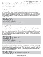
Case Study: West Florida Mall (continued)
In Chapter 2 we chose our primary entity, MALL, and used structured
English to describe it, its attributes and keys, and then we mapped MALL to
a relational database (with some sample data). In this chapter we continue to
develop this case study by looking at steps 3, 4, and 5, of the ER design
methodology, and then mapping the entities that are developed into a
relational database with some sample data.
Step 3 says:
Step 3: Examine attributes in the primary entity (with user assistance)
to find out if information about one of the entities is to be recorded.
Upon reexamining the attributes of the primary entity, MALL, it appears that
we need to store information about the attribute, store. So we look at Step
3a, which says:
Step 3a: If information about an attribute is needed, then make the
attribute an entity, and then Step 3b.
So, turning the attribute, store, into an entity we have (repeating step 2):
The Entity
This database records data about a STORE. For each STORE
in the database, we record a store name (sname), a store
number (snum), a store location (sloc), and departments
(dept).
The Attributes for STORE
For each STORE, there will always be one and only one
sname (store name). The value for sname will not be
subdivided.
For each STORE, there will always be one and only one snum
(store number). The value for snum will be unique, and not be
subdivided.
For each STORE, we will record a sloc (store location). There
will be one sloc recorded for each STORE. The value for sloc
will not be subdivided.
For each STORE, we will record depts (departments). There
will be more than one depts recorded for each STORE. The
value for depts will not be subdivided.
The Keys
For each STORE, we will assume that the snum will be unique.
Note: Once STORE is made into an entity, the attribute, store, is removed
from the entity MALL, as shown in Figure 3.7
.
Figure 3.7:
An ER Diagram of the Mall Database Thus
Far
Having defined STORE, we now need to follow Step 3b, which says:
Step 3b: Define the relationship back to the original entity.
There is a relationship, located_in, between STORE and MALL. This is
shown in Figure 3.7
.
Next, Step 4 says:
Step 4: If another entity is appropriate, draw the second entity with its
attributes. Repeat Step 2 to see if this entity should be further split into
more entities.
We will select another entity, STORE_MANAGER. Now, repeating step 2 for
STORE_MANAGER:
The Entity
This database records data about a STORE_MANAGER.
For each STORE_MANAGER in the database, we record a
store manager name (sm_name), store manager social
security number (sm_ssn), and store manager salary
(sm_salary).
The Attributes for STORE_MANAGER
For each STORE_MANAGER, there will always be one and
only one sm_name (store manager name). The value for
sm_name will not be subdivided.
For each STORE_MANAGER, there will always be one and
only one sm_ssn (store manager ssn). The value for sm_ssn
will be unique, and not be subdivided.
For each STORE_MANAGER, we will record a sm_salary
(store manager salary). There will be one and only one
sm_salary recorded for each STORE_MANAGER. The value
for sm_salary will not be subdivided.
The Keys
For each STORE_MANAGER, we will assume that the sm_ssn
will be unique.
Having defined STORE_MANAGER, we now follow Step 5, which says:
Step 5: Connect entities with relationships if relationships exist.
There is a relationship, manages, between STORE and
STORE_MANAGER. This is shown in Figure 3.8
.
Figure 3.8:
An ER Diagram of West Florida Mall Database
Developing
Then we select our next primary entity, STORE_OWNER. Now, repeating
step 2 for STORE_OWNER:
The Entity
This database records data about a STORE_OWNER. For
each STORE_OWNER in the database, we record a store
owner name (so_name), store owner social security number
(so_ssn), store owner's office phone (so_off_phone), and store
owner address (so_address).
The Attributes for STORE_OWNER
For each STORE_OWNER, there will always be one and only
one so_name (store owner name). The value for so_name will
not be subdivided.
For each STORE_OWNER, there will always be one and only
one so_ssn (store owner ssn). The value for so_ssn will be
unique, and will not be subdivided.
For each STORE_OWNER, there will always be one and only
one so_off_phone (store owner office phone). The value for
so_off_phone will be unique, and will not be subdivided.
For each STORE_OWNER, we will record a so_address (store
owner address). There will be one and only one so_address
recorded for each STORE_OWNER. The value for so_address
will not be subdivided.
The Keys
For each STORE_OWNER, we will assume that the so_ssn
will be unique. Having defined STORE_OWNER, we now
follow Step 5, which says:
Step 5: Connect entities with relationships if relationships exist.
There is a relationship, owns, between STORE and OWNER. This is shown
in Figure 3.9
.
Figure 3.9:
An ER Diagram of West Florida Mall with Four
Entities
Mapping the Entity to a Relational Database
Having described the entities, attributes, and keys, the next step would be to
map the entities to a relational database. We will also show some data for
the entities developed, in this part of the case study (the mappings of the
relationships will be shown at the end of Chapter 4
).
Relations for the MALL Entity
The first two relations, MALL–Store and MALL are the same as they were in
Chapter 2
:
Relations for the STORE Entity
The entity, STORE, has a multi-valued attribute, depts, so we will again have
to use mapping rule M1 and M1c (as stated in Chapter 2
) to map this entity.
First, we will show the relation with the multi-valued attribute excised, and
then we will show the relation with the multi-valued attribute. (Note: We are
developing this database for the West Florida Mall, so we will map only its
stores.)
Relation with the Multi-Valued Attribute Excised
Relation with the Multi-Valued Attribute
MALL–Store
name store_name
West Florida Mall Penney's
West Florida Mall Sears
West Florida Mall Dollar Store
West Florida Mall Rex
Cordova Mall Dillards
.
.
.
MALL
name address
West Florida Mall N Davis Hwy, Pensacola, FL
Cordova Mall 9th Avenue, Pensacola, FL
Navy Mall Navy Blvd, Pensacola, FL
BelAir Mall 10th Avenue, Mobile, AL
STORE
sloc sname snum
Rm 101 Penney's 1
Rm 102 Sears 2
Rm 109 Dollar Store 3
Rm 110 Rex 4
Relation for the STORE MANAGER Entity (using mapping
rule M1 and M1a)
Relation for the OWNER Entity (using mapping rule M1 and
M1a)
STORE–dept
snum depts
1 Tall men's clothing
1 Women's clothing
1 Children's clothing
1 Men's clothing
.
2 Men's clothing
2 Women's clothing
2 Children's clothing
2 Hardware
.
.
.
STORE MANAGER
sm_ssn sm_name sm_salary
234–987–0988 Saha 45,900
456–098–0987 Becker 43,989
928–982–9882 Ford 44,000
283–972–0927 Raja 38,988
OWNER
so_ssn so_name so_off_phone so_address
879–987–
0987
Earp (850)474–2093 1195 Gulf Breeze Pkwy,
Pensacola, FL
826–098–
0877
Sardar (850)474–9873 109 Navy Blvd,
Pensacola, FL
928–088–
7654
Bagui (850)474–9382
89
Highland Heights,
Tampa, FL
982–876–
8766
Bush (850)474–9283 987 Middle Tree,
Mobile, AL
So far our relational database has developed into (without the data):
[Note:
The primary keys are underlined.]
MALL-Store
MALL
STORE
STORE-dept
OWNER
STORE MANAGER
This case study will be continued at the end of Chapter 4
.
name store_name
name address
sloc sname snum
snum depts
so_ssn so_name so_off_phone so_address
sm_ssn sm_name sm_salary