WINDOWS 2000 TROUBLE SHOOTING TCP/I P phần 9 pot
Bạn đang xem bản rút gọn của tài liệu. Xem và tải ngay bản đầy đủ của tài liệu tại đây (453.41 KB, 74 trang )
566 Chapter 11 • Troubleshooting Windows 2000 Connectivity Problems at the Internetwork Level
networks (such as ATM or X.25). OSPF has different protocols for broad-
cast and multicast network types.
OSPF uses the Dijkstra algorithm, which comes from the branch of
mathematics known as graph theory, to calculate the lowest-cost path to a
destination from a given source.
OSPF on a Broadcast Network
On a broadcast network, OSPF uses a packet called a Hello protocol mes-
sage, which is a broadcast message by which routers locate one another.
A router is selected to be the Designated Router (DR), and all the other
routers exchange routing information with the DR. Then, the DR updates
neighboring routers.
The DR is elected by an exchange of Hello packets. Each packet
includes the current DR, the sending router’s router ID, and its router
priority (which can be set during configuration of OSPF). The router with
the highest priority is selected to be the DR. If more than one router has
the same priority, the one that has the highest router ID will become the
DR.
A backup DR is also elected for multiaccess networks, so if the DR
becomes unavailable, connectivity will not be lost.
Configuring an OSPF router with a priority of 0 means it cannot become a
DR. There must be at least one router on the multiaccess network that has
a priority of 1 or above. Otherwise, no router can become DR and the link
state database cannot be synchronized, resulting in no traffic being passed
across that network.
OSPF on a Nonbroadcast Network
On a network using a nonbroadcast architecture, such as ATM, OSPF has
to be initially configured manually with the addresses of neighboring
routers. A DR is also used, but rather than sending the routing informa-
tion via broadcast or multicast, it is sent point to point, between the DR
and the other routers. This means a greater number of virtual
NOTE
WARNING
91_tcpip_11.qx 2/25/00 11:17 AM Page 566
Troubleshooting Windows 2000 Connectivity Problems at the Internetwork Level • Chapter 11 567
connections are required for complete connectivity, making it more com-
plex and more resource-intensive than a broadcast network implementa-
tion.
OSPF on a Point-to-Point Network
OSPF can also be used on a dedicated point-to-point network such as T-1
leased lines, connecting only two routers. IP multicast addresses are used
for the OSPF messages.
OSPF’s Hierarchical Routing Structure
The routing tables used by a distance vector protocol like RIP have a flat
structure, and every RIP router on the internetwork must contain an
entry for every network. The networks are not divided into areas or
groups; all are seen as individual entities—thus the “flat” description.
Link state protocols like OSPF create a hierarchical structure by dividing
the internetwork into areas. Every OSPF router belongs to an area, identi-
fied by a 32-bit number, expressed in dotted decimal called the area num-
ber. This greatly reduces the size of the routing table for each router,
since it only has to keep entries for its area.
Although the area address is in the same format as an IP address, it is an
entirely different number, assigned by the administrator. It has no
relationship to the network ID, although if the networks in an area are all in
one subnetted network ID, you could, for convenience, use the network ID
as the Area ID. Windows 2000 allows you to configure up to 16 areas for
an interface.
There is also a backbone area designated as area 0.0.0.0. The router
that connects an area to the backbone area is called an Area Border
Router (ABR). This router is a member of its area and contains routing
information for that area, but also is a member of area 0.0.0.0 and can
route between the two areas. See Figure 11.12 for an illustration of this.
The ABR has a separate link state database for each area to which it
belongs, and SPF calculations are performed independently for each area.
NOTE
91_tcpip_11.qx 2/25/00 11:17 AM Page 567
568 Chapter 11 • Troubleshooting Windows 2000 Connectivity Problems at the Internetwork Level
OSPF Areas
An area can consist of one or more networks or subnets. The advantage
of splitting the internetwork into areas is that you reduce the bandwidth
used for routing so that it is proportionate to the size of the area rather
than the size of the internetwork as a whole.
ABRs can summarize the routes within their areas. Route summariza-
tion means that each ABR communicates a single route for its area to the
backbone router. Thus, the Area 0.0.0.0 routing table contains only the
number of routes that correspond to the number of areas, rather than all
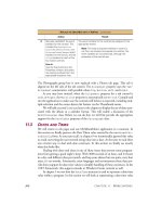
routes for each area. In Figure 11.12, Area 0.0.0.0’s database would be
required to contain only four routes, regardless of how many routers and
routes exist within each of the four areas.
Route summarization also decreases recalculations of routes.
Whenever a network is added or removed, each OSPF router must recal-
culate the database. By using areas, if a new network is added to Area
0.0.1.1, the routers in other areas will not be required to recalculate since
the summarized route is still valid.
Figure 11.12 The hierarchical structure of OSPF routing architecture.
Area 0.0.1.1
Area 0.0 0.1 Area 0.0.1.0
Area 0.1.0.0
Area 0.0.0.0
(The backbone
area)
ABRRouter ABR
ABR ABR
Router Router
Router
Router
Router Router Router
Router
Router
Router Router
91_tcpip_11.qx 2/25/00 11:17 AM Page 568
Troubleshooting Windows 2000 Connectivity Problems at the Internetwork Level • Chapter 11 569
OSPF Router Classifications
OSPF routers on the internetwork are designed as one of the following:
■
ABR Area Border Router (routes between the area to which it
belongs and the backbone area).
■
IR Internal Router (routes within its area).
■
BR Backbone Router (Area 0.0.0.0 router).
■
ASBR Autonomous System Border Router (used on global
internetworks, such as the Internet, to add another layer of the
hierarchy. An Autonomous System, or AS, represents an entire
enterprise network within the global internetwork).
AS numbers are allocated by the Internet Assigned Numbers Authority
(IANA), as they must be globally-unique.
OSPF uses 32-bit router identification numbers (router IDs) rather
than the routers’ IP addresses to keep track of individual routers on the
internetwork. This is because each router will have more than one IP
address.
The administrator assigns the router ID. It is common practice, although in
no way required, to use the router’s lowest IP address for its router ID.
The Protocols Used by OSPF
The following protocols are used within OSPF:
Common header protocol. The common header used for OSPF
messages includes the version number, type, packet length, the
router ID, Area ID, a checksum, and an authentication field
(messages can be sent with password authentication or no
authentication).
Hello protocol. The Hello protocol is used on broadcast networks
to discover the identities and routes of neighboring routers.
NOTE
TIP
91_tcpip_11.qx 2/25/00 11:17 AM Page 569
570 Chapter 11 • Troubleshooting Windows 2000 Connectivity Problems at the Internetwork Level
Exchange protocol. The Exchange protocol uses database
description packets in a master-slave relationship. The master
sends the database description packets, and the slave sends an
acknowledgment.
Flooding protocol. The Flooding protocol is used when a link
changes state, as when the link between two routers goes down.
The router that is responsible for the changed link issues the new
link state information, and the updated information is sent in
regular intervals until an acknowledgment is received.
Aging Link State Records protocol. The Aging Link State Records
protocol is used to remove old, outdated records from the
database. When the record is originally issued, its age is set as 0.
It is incremented by 1 every second and on each hop, and when its
age matches the designated maximum, the router removes it and
informs neighboring routers of the change.
Advantages of OSPF
Despite the fact that it is much more complex and requires more techni-
cal expertise to implement properly, OSPF has many advantages over RIP
and other distance vector protocols:
■
More efficient calculation of routes
■
Faster convergence
■
Support for load balancing
■
Low bandwidth utilization
■
No routing loops or count-to-infinity problems
■
Hierarchical structure isolates instability within an area
■
More scalability, appropriate for larger networks
■
Secure password authenticated transmission of update
messages
Windows 2000 as an IP Router
A Windows 2000 multihomed host computer is configured as an IP router
to provide packet forwarding for other TCP/IP computers by enabling the
RRAS service and setting up a routed IP network. This can be a static
routed network, a RIP for IP routed internetwork, or an OSPF routed
internetwork. For more information about installing RRAS, see Chapter 9,
“Troubleshooting Remote Access in a Windows 2000 TCP/IP Network.”
The Windows 2000 router supports both RIP (versions 1 and 2) and
OSPF dynamic routing protocols.
91_tcpip_11.qx 2/25/00 11:17 AM Page 570
Troubleshooting Windows 2000 Connectivity Problems at the Internetwork Level • Chapter 11 571
Installing Routing Protocols
The Windows 2000 router supports dynamic routing, using RIP or OSPF.
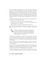
To install the RIP or OSPF protocol, open the RRAS management console.
In the left console pane, expand the name of the RRAS server, expand IP
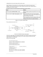
Routing, and right-click General. Select New Routing Protocol, as shown
in Figure 11.13.
Figure 11.13 Adding a dynamic routing protocol to the Windows 2000 router.
You will be given a choice to select either RIP or OSPF. Make the
appropriate choice, and the protocol will be added. You can now configure
it by right-clicking on its name, which will show up in the left console
pane under IP Routing.
91_tcpip_11.qx 2/25/00 11:17 AM Page 571
572 Chapter 11 • Troubleshooting Windows 2000 Connectivity Problems at the Internetwork Level
Windows 2000 Router Management Tools
Windows 2000 provides built-in router management tools for the adminis-
tration of the static, RIP, or OSPF router. A Windows 2000 router can be
administered locally or remotely from another Windows 2000 computer
running RRAS.
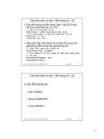
Remote Router Administration
Windows 2000 allows you to administer a remote Windows 2000 router
via the RRAS management console. To do so, open the RRAS MMC, and
in the left pane of the console tree, right-click Server Status, then Add
Server. A dialog box as shown in Figure 11.14 will appear.
Figure 11.14 Use the Add Server dialog box to select the computer(s) to
administer remotely.
As you can see, you can select “The following computer:” and type in
the name of the Windows 2000 router computer, you can select to admin-
ister all RRAS computers in a designated domain, or you can browse the
Active Directory to find the computer to be administered.
If you choose to browse the Directory, you will see a dialog box like
the one displayed in Figure 11.15.
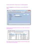
If you elect to administer all RRAS servers in the domain, the names
of all Windows 2000 computers in the domain running RRAS will be dis-
played in the left console of the MMC, as shown in Figure 11.16.
You may notice in Figure 11.16 that there are three Windows 2000
computers running RRAS in the tacteam domain. One of them, DS2000,
is marked with a red and white “X” to indicate that this computer is not a
router or RRAS server and cannot be administered remotely (DS2000 is a
Windows 2000 Professional workstation).
91_tcpip_11.qx 2/25/00 11:17 AM Page 572
Troubleshooting Windows 2000 Connectivity Problems at the Internetwork Level • Chapter 11 573
You can now add new interfaces and routing protocols, and manage
the routing components on the remote Windows 2000 router computer
just as you could locally.
Figure 11.15 You can browse the Directory to find Windows 2000 routers or
RAS servers.
Figure 11.16 Windows 2000 RRAS computers that can be remotely
administered are displayed.
91_tcpip_11.qx 2/25/00 11:17 AM Page 573
574 Chapter 11 • Troubleshooting Windows 2000 Connectivity Problems at the Internetwork Level
Using ICMP Router Discovery
You can use the Internet Control Message Protocol (ICMP), a TCP/IP utili-
ty, to configure IP host computers with the IP addresses of local routers
(and establish a method for the hosts to detect that a router is down). To
do so, implement router solicitation and advertisement.
ICMP router discovery messages are discussed in RFC 1256.
Here’s how it works:
1. Host computers send router solicitation messages to discover
the routers on their networks.
2. Routers send router advertisement messages in response to the
solicitations. The routers also send advertisements on a regular
basis (unsolicited) to inform the host computers that the routers
are still up and available.
To enable ICMP router discovery, open the RRAS console, and in the
left pane of the console tree, under the Windows 2000 router on which
you wish to enable discovery messages, click General under IP Routing.
In the right console pane, right-click the name of the router interface you
wish to enable for ICMP, then click Properties. Select the General tab, as
shown in Figure 11.17, and check the “Enable router discovery advertise-
ments” check box.
Here, you can set the lifetime of the advertisement (the time after
which a router will be considered to be down or unavailable) in minutes.
You can also set the minimum and maximum rates for sending of ICMP
advertisements by the router. “Level of preference” refers to the level of
preference for this Windows 2000 router to be the default gateway for
host computers on the network.
Using the Netshell Utility (NETSH)
NETSH is a command-line utility included with Windows 2000, with
which you can configure routes, interfaces, and routing protocols on
Windows 2000 RRAS routers. The NETSH utility will allow you to display
the configuration of routers that are running on Windows 2000 RRAS
computers, and supports scripting so that you can run commands as
batch files for a particular router.
NOTE
91_tcpip_11.qx 2/25/00 11:17 AM Page 574
Troubleshooting Windows 2000 Connectivity Problems at the Internetwork Level • Chapter 11 575
NETSH is used for management of other services, such as DHCP and
WINS. To change the NETSH context to routing, use the routing com-
mand within NETSH, as shown in Figure 11.18.
Figure 11.17 Enabling router discovery advertisement messages.
Figure 11.18 Use the NETSH command to display routing information.
91_tcpip_11.qx 2/25/00 11:17 AM Page 575
576 Chapter 11 • Troubleshooting Windows 2000 Connectivity Problems at the Internetwork Level
Table 11.3 lists some of the commands available in the IP routing con-
text.
Table 11.3 Netshell IP Routing Commands
Command Description
add Adds a configuration entry to a table
delete Deletes a configuration entry from a table
dump Dumps a configuration script
igmp Changes to 'routing ip igmp' context
nat Changes to 'routing ip nat' context
ospf Changes to 'routing ip ospf' context
relay Changes to 'routing ip relay' context
reset Resets IP routing to clean state
rip Changes to 'routing ip rip' context
routerdiscovery Changes to 'routing ip routerdiscovery' context
set Sets configuration information
show Displays information
Update Updates autostatic routes on an interface
? Displays help
Standard TCP/IP tools, such as PING, TRACERT, and PATHPING, are
the common starting point for troubleshooting an IP routing problem. See
Chapter 4, “Windows 2000 TCP/IP Internals,” for more information on
how to use these command-line utilities.
Router Configuration
Proper configuration of the router(s) will prevent many problems.
Configuring Windows 2000 as an IP router, for either static routing or
using RIP or OSPF, is a relatively painless procedure, but it is important
that you follow the steps exactly and don’t change settings unless you
know what effect it will have.
Preconfiguration Check List
Remember that before installing and configuring IP routing, you must
ensure that the following have been done:
91_tcpip_11.qx 2/25/00 11:17 AM Page 576
Troubleshooting Windows 2000 Connectivity Problems at the Internetwork Level • Chapter 11 577
■
Install the proper hardware (the Windows 2000 computer acting
as a router must have two network interfaces) and the drivers
for the hardware. Check the Windows 2000 HCL to ensure
compatibility of the hardware.
■
TCP/IP must, of course, be installed and configured.
■
The RRAS service must also be enabled and configured (see
Chapter 9 for more information on proper installation of RRAS).
■
Determine whether you will set up the Windows 2000 router for
static or dynamic routing.
■
Determine which routing protocols will be used on the network.
Configuring Windows 2000 Static IP Routing
Deployment of static routing on a Windows 2000 router is relatively sim-
ple. You should first analyze the internetwork topology, to determine
where each network is and where routers and TCP/IP host computers are
located on the networks. Then, a unique network ID is assigned to each
IP network, and IP addresses are assigned to each router interface.
Common practice is to give the lowest IP addresses for the network ID to
the routers. Thus, for network 192.168.1.0 (a class C network defined by a
subnet mask of 255.255.255.0), the router (default gateway) address that
would be assigned is 192.168.1.1. This is not required, but is an industry
tradition.
Default routes can be configured on peripheral routers, although this
is not required. A default route is used for sending packets to a destina-
tion for which there is no route available in the routing table.
Nonperipheral routers (internal routers) should have routes to remote
networks added to their routing tables as static routes. Each route should
include the following:
■
Destination network ID
■
Subnet mask
■
Gateway address
■
Metric (number of hops required to get to the destination
network)
■
Interface that is to be used to send data to the destination
network
TIP
91_tcpip_11.qx 2/25/00 11:17 AM Page 577
578 Chapter 11 • Troubleshooting Windows 2000 Connectivity Problems at the Internetwork Level
These static routes should be entered in the routing tables of each
nonperipheral router.
Routes are added using the command-line ROUTE utility. To make a route
persistent across system reboots, use the –p option.
Troubleshooting Static Routing Configuration
If the router is not forwarding data properly in a static routing environ-
ment, you should do the following:
1. First, confirm that IP routing is enabled on the Windows 2000
router, by checking the RRAS management console.
2. Use IPCONFIG at the command line to ensure that the TCP/IP
configuration for the interface is correct. Use standard TCP/IP
tools such as PING to verify connection to hosts on the network
segment.
3. Ensure that the default route is configured correctly. The default
route is used for sending packets to destinations that are
unknown to the router. Be sure that the route set as the
gateway for the route is reachable and is on the same network
as the interface.
Routers should be configured to use a static IP address, instead of getting
an IP address via DHCP.
Configuring RIP for IP
Remember that RIP is most appropriately used for medium-sized internet-
works (those consisting of 10 to 50 networks). RIP can be used with mul-
tipath networks, where there is more than one pathway a packet could
take between two endpoints on the network. RIP will also work in an envi-
ronment where the network topology changes, and networks are added
and removed.
TIP
NOTE
91_tcpip_11.qx 2/25/00 11:17 AM Page 578
Troubleshooting Windows 2000 Connectivity Problems at the Internetwork Level • Chapter 11 579
In designing the RIP network, keep in mind the maximum hop count
limitation of 15. This limits the number of routers through which a pack-
et must go to reach any destination from any source, for practical pur-
poses, to 14 (called the maximum physical router diameter).
As in deploying static routing, you should first analyze the internet-
work, assign network IDs, and assign IP addresses, following the same
basic rules discussed earlier. Then, decide whether to use RIPv1 or RIPv2
on each Windows 2000 computer functioning as a router. Add the appro-
priate RIP protocol to each Windows 2000 router interface, as shown in
Figure 11.19.
Figure 11.19 Adding the RIP protocol to a router interface.
Once the protocol has been added, right-click the Interface name in
the right console pane of the MMC, and select Properties to configure it
(see Figure 11.20).
To configure RIPv2, do the following:
1. In Outgoing Packet Protocol on the General tab of the Properties
sheet: a) select RIPv2 broadcast if there are version 1 RIP
91_tcpip_11.qx 2/25/00 11:17 AM Page 579
580 Chapter 11 • Troubleshooting Windows 2000 Connectivity Problems at the Internetwork Level
routers on this network, or b) select RIPv2 multicast if all RIP
routers on the network are version 2 routers.
2. In Incoming Packet Protocol, select RIP, version 1 and 2 if it is a
mixed RIP environment, and RIP, version 2 only if there are only
RIPv2 routers on this network.
Figure 11.20 RIP Properties dialog box.
Troubleshooting RIP Configuration
Some of the more common RIP configuration problems include incorrect
routes in the mixed RIP (version 1 and 2) environment, silent hosts not
getting route updates, auto-static updates not working properly, and host
routes and/or default routes not being propagated to other routers.
Problems with Mixed RIP Versions
When a network includes some routers running RIPv1 and others run-
ning RIPv2, the version 2 routers must be configured to send broadcasts
if you want the version 1 routers to receive their announcements. If you
have this problem, ensure that your RIPv2 router interfaces are all set to
broadcast their announcements, not multicast.
91_tcpip_11.qx 2/25/00 11:17 AM Page 580
Troubleshooting Windows 2000 Connectivity Problems at the Internetwork Level • Chapter 11 581
Problems with Silent Hosts
RIP listeners (silent hosts) cannot receive multicast announcements. If
you have silent RIP hosts that fail to receive announcements, confirm that
the silent hosts are using RIPv1 and that the RIPv2 routers on the net-
work are set to send broadcast, not multicast, announcements.
Problems with Autostatic Updates
If you have demand-dial routing interfaces using auto-static updates (see
Chapter 9 for more information about RRAS demand dial), the demand-
dial interfaces need to be set to broadcast announcement messages
instead of multicasting.
Autostatic updates are used with demand-dial routing over a remote
access link. The “auto” in the term refers to the automatic adding of the
requested routes as static routes in the routing table upon an explicit
request via RRAS or the NETSH utility. The demand-dial link must be
connected.
If an autostatic request is made, existing autostatic routes that are in
the table are deleted. Then, the update is requested from other routers.
This can lead to problems: If other routers don’t response to the update
request, the router cannot replace the routes it has deleted. This could
cause loss of connectivity to remote networks.
Problems with Propagation of Host and Default Routes
RIP does not propagate host and default routes by default. You must
specifically enable propagation, which can be done by right-clicking the
Interface name in the right console pane of the RRAS MMC, selecting
Properties, and then selecting Advanced. See Figure 11.21.
The RIP Properties box is also used to set Security on the update
announcement messages and to specify RIP neighbors and determine the
router’s behavior in regard to those neighbors.
Configuring OSPF
The OSPF dynamic routing protocol is installed similarly to RIP, via the
New Protocol selection, when you right-click the General tab under IP
Routing in the RRAS management console.
Once the protocol is enabled, configure it by following these steps:
1. Click on OSPF in the left pane console tree.
2. In the right pane, right-click the interface you want to configure,
and choose Properties.
91_tcpip_11.qx 2/25/00 11:17 AM Page 581
582 Chapter 11 • Troubleshooting Windows 2000 Connectivity Problems at the Internetwork Level
3. Select the “Enable OSPF for this address” check box on the
General tab. Where it says Area ID, click the ID of the area to
which this interface belongs.
4. Set the priority of the router over the interface in “Router
priority.”
5. Use the scroll arrows to set the cost of sending a packet over the
interface under Cost.
6. Type in a password, if password protection is enabled for that
area.
7. Select the OSPF interface type under Network type.
If this interface has more than one IP address configured, select the IP
Address box on the General tab and configure OSPF for each address.
The OSPF Interface Properties dialog box appears in Figure 11.22.
Figure 11.21 Setting RIP to propagate host and default routes in the Advanced
Properties box.
TIP
91_tcpip_11.qx 2/25/00 11:17 AM Page 582
Troubleshooting Windows 2000 Connectivity Problems at the Internetwork Level • Chapter 11 583
OSPF Password Protection
All OSPF routers in the Area must use the same password. To set the
password, click OSPF in the left pane of the console tree, and select
Properties. On the General tab, type the correct password in the
Password box. Remember that OSPF passwords are case-sensitive.
Windows 2000 Router Logging
You can enable router logging for the Windows 2000 router to assist you
in troubleshooting routing problems. You can either enable event logging,
to log router events in the system log in Event Viewer, or enable trace log-
ging, which will log information to a file (or you can do both).
Using Event Logging
You can enable event logging on the Event Logging tab on the Properties
sheet of a remote access server. Choose the RRAS server, right-click and
select Properties, then select the Event Logging tab, as shown in Figure
11.23.
Figure 11.22 The OSPF Interface dialog box showing the contents of the
General tab.
91_tcpip_11.qx 2/25/00 11:17 AM Page 583
584 Chapter 11 • Troubleshooting Windows 2000 Connectivity Problems at the Internetwork Level
You can choose the level of information you wish to be logged to the
system log. There are four levels: logging of errors only, logging of errors
and warning messages, logging of the maximum possible amount of infor-
mation, or no logging (disabled).
The default setting is logging of errors and warning messages.
Remember that logging uses a great deal of system resources and
should be used only when necessary and disabled when the problem has
been addressed.
Using the Tracing Function
The Windows 2000 router supports tracing, a feature that can be used for
troubleshooting complex network routing problems. When you enable tracing
in Windows 2000 Server, the tracing information will be logged to files.
Figure 11.23 You can select from four levels of event logging in the RRAS
server Properties sheet.
NOTE
91_tcpip_11.qx 2/25/00 11:17 AM Page 584
Troubleshooting Windows 2000 Connectivity Problems at the Internetwork Level • Chapter 11 585
To enable the tracing feature, it is necessary to edit the Windows 2000
Registry.
Editing the Windows 2000 Registry incorrectly can cause serious damage to
the operating system, including making your computer unbootable. Always
back up important data before you make changes to the Registry.
To enable tracing, open the following Registry key:
HKEY_LOCAL_MACHINE\SOFTWARE\Microsoft\Tracing
Tracing is enabled separately for each routing protocol, by setting the
appropriate Registry values. Each of the routing protocols appears as a
subkey in the Registry, under the Tracing key. Select the protocol for
which you wish to enable tracing (for example, OSPF).
Tracing can be enabled or disabled while the router is running.
Configure the following Registry value entries for each protocol key to
enable tracing for that protocol:
■
EnableFileTracing (value type is REG_DWORD) Set
EnableFileTracing to 1 (the default value is 0) to enable logging
tracing information to a file.
■
FileDirectory (value type is REG_EXPAND_SZ ) To change the
default location of the tracing files, set the FileDirectory value to
the desired path. The filename for the log file is the name of the
component for which tracing is enabled. Tracomg log files are
placed in the systemroot\Tracing folder by default.
■
FileTracingMask (value type is REG_DWORD) This setting
indicates how much tracing information is logged to the file.
■
MaxFileSize (value type is REG_DWORD) Set this value to
change the size of the log file. The default value is 10000 (64K).
WARNING
TIP
91_tcpip_11.qx 2/25/00 11:17 AM Page 585
586 Chapter 11 • Troubleshooting Windows 2000 Connectivity Problems at the Internetwork Level
Tracing uses a significant amount of system resources. Use it sparingly for
identification of network problems. After you capture the trace, disable
tracing. Never leave tracing enabled on multiprocessor systems.
Troubleshooting Common Windows 2000
Routing Problems
Now that we have discussed how IP routing works in a static, RIP, or
OSPF environment, let’s look at some of the common problems that arise
with Windows 2000 computers configured to perform IP routing.
Troubleshooting Static Routing
Because static routing is much less complex than dynamic routing, trou-
bleshooting is in some ways simplified. The standard TCP/IP command-
line utilities can be used for many troubleshooting tasks. Remember that
static routing is appropriate for small, simple internetworks (no more
than 10 subnetworks). For best results, there should be only one path
available between any two endpoints, and the internetwork topology
should not change often.
Using PING and TRACERT
Test connectivity between the host computers using the TCP/IP utilities
PING and TRACERT (as discussed in Chapter 4, “Windows 2000 TCP/IP
Internals”) to ensure that routing paths are accessible.
Using the ROUTE Command
As discussed earlier, static entries are made to the routing table using the
ROUTE command and its options. You can also modify or delete routes,
and make routes persistent over reboots.
Static Routing and Routing Loops
A problem that can occur in a network using static routing happens when
you configure two routers with default routes that point to one another. A
default route is used for data packets addressed to destinations that
reside on remote networks (networks not directly connected to the router).
If two neighboring routers have default routes that point to one another,
TIP
91_tcpip_11.qx 2/25/00 11:17 AM Page 586
Troubleshooting Windows 2000 Connectivity Problems at the Internetwork Level • Chapter 11 587
this can create a routing loop when packets are sent to unreachable des-
tinations. To prevent this problem, don’t configure neighboring routers
with default routes pointing to each other.
The following shows what a router loop might look like after doing a
tracert:
C:\>tracert 199.70.51.234
Tracing route to 199.70.51.234 over a maximum of 30 hops
1 <10 ms <10 ms <10 ms starblazer.tacteam.net [192.168.1.16]
2 441 ms 561 ms 330 ms tnt-dal.dallas.net [209.44.40.10]
3 180 ms 741 ms 561 ms grf-dal-ge002.dallas.net [209.44.40.9]
4 311 ms 711 ms 681 ms atm9-0-04.CR-1.DllsTX.savvis.net [209.44.32.9]
5 691 ms 551 ms 331 ms sl-gw13-fw-10-0-T3.sprintlink.net [144.228.137.5
]
6 471 ms 711 ms 540 ms sl-bb11-fw-2-2.sprintlink.net [144.232.11.65]
7 691 ms 551 ms 340 ms sl-gw17-fw-4-0-0.sprintlink.net [144.232.11.106]
8 521 ms 391 ms 671 ms sl-att-5-0-0-T3.sprintlink.net [144.232.193.70]
9 721 ms 531 ms 340 ms gbr2-a90s6.dlstx.ip.att.net [12.123.16.22]
10 661 ms 341 ms 701 ms gbr2-p40.attga.ip.att.net [12.122.2.90]
11 481 ms 681 ms 541 ms gbr2-p40.wswdc.ip.att.net [12.122.3.238]
12 351 ms 621 ms 560 ms br2-a340s8.wswdc.ip.att.net [12.127.7.190]
13 370 ms 511 ms 330 ms dc2-h110.mdtva.ip.att.net [12.127.15.5]
14 501 ms 391 ms 671 ms 12.127.11.238
15 501 ms 801 ms 541 ms dc2-a350s1.mdtva.ip.att.net [12.127.11.237]
16 701 ms 801 ms 671 ms 12.127.11.238
17 571 ms 391 ms 550 ms dc2-a350s1.mdtva.ip.att.net [12.127.11.237]
18 581 ms 671 ms 551 ms 12.127.11.238
19 791 ms 541 ms 471 ms dc2-a350s1.mdtva.ip.att.net [12.127.11.237]
20 741 ms 661 ms 390 ms 12.127.11.238
21 711 ms 560 ms 391 ms dc2-a350s1.mdtva.ip.att.net [12.127.11.237]
22 591 ms 380 ms 761 ms 12.127.11.238
23 540 ms 661 ms 571 ms dc2-a350s1.mdtva.ip.att.net [12.127.11.237]
24 721 ms 801 ms 551 ms 12.127.11.238
25 691 ms 842 ms 520 ms dc2-a350s1.mdtva.ip.att.net [12.127.11.237]
26 731 ms 751 ms 791 ms 12.127.11.238
27 561 ms 711 ms 541 ms dc2-a350s1.mdtva.ip.att.net [12.127.11.237]
28 611 ms 781 ms 802 ms 12.127.11.238
29 621 ms 811 ms 841 ms dc2-a350s1.mdtva.ip.att.net [12.127.11.237]
30 580 ms 842 ms 751 ms 12.127.11.238
91_tcpip_11.qx 2/25/00 11:17 AM Page 587
588 Chapter 11 • Troubleshooting Windows 2000 Connectivity Problems at the Internetwork Level
Troubleshooting RIP for IP
Testing and troubleshooting a RIP network can be done using tools that
are built into Windows 2000. Proper planning and multiphased deploy-
ment that includes testing of each added feature will make problem isola-
tion and solutions easier.
Viewing RIP Neighbors
The ability to view the Windows 2000 router’s RIP neighbors is useful for
verifying that the router is receiving RIP announcements from all of its
neighboring RIP routers. To view RIP neighbors, open the RRAS manage-
ment console, and in the left pane of the console tree, right-click RIP and
select Show Neighbors, as shown in Figure 11.24.
Figure 11.24 To view the neighboring RIP routers, right-click RIP and select
Show Neighbors.
This will allow you to see the IP address of RIP neighbors, the RIP ver-
sion each is using, and bad packets and bad routes for each.
91_tcpip_11.qx 2/25/00 11:17 AM Page 588
Troubleshooting Windows 2000 Connectivity Problems at the Internetwork Level • Chapter 11 589
Viewing the Routing Table
The Windows 2000 routing table can be viewed either via the command-
line utility ROUTE PRINT or through the RRAS graphical interface, as dis-
cussed earlier in this chapter. Examine the routing table and confirm that
all routes that should be learned from RIP are entered in the table.
Summary: Common RIP Problems
Following are some tips for troubleshooting problems that commonly
occur when using RIP routing.
RIP Router Does Not Receive Routes Properly
If a Windows 2000 router that is using RIP does not receive the expected
routes, it can be because of the way in which your network is subnetted.
Variable-length subnet masking, or using supernetting in a network
where RIP, version 1 is deployed, can result in routes not being propagat-
ed properly. This is because RIP, version 1 does not support variable-
length subnet masking; however, RIP, version 2 does support it.
The solutions to this problem are:
■
Don’t use variable-length subnetting or supernetting, or deploy
RIP, version 2 only on the network.
■
If you are using authentication, ensure that all network
interfaces are using the same password (passwords are case-
sensitive).
■
Ensure that RIP route filtering, if enabled, is configured
properly.
■
If you have configured RIP neighbors, ensure that the correct IP
addresses are entered for unicast announcements.
■
Ensure that packet filtering is not filtering out RIP
announcements.
When password protection is enabled on a RIPv2 router, the password is
sent in plain text format. This means any user with network sniffer
software, such as the Microsoft Network Monitor, can capture the RIPv2
announcements and view the password.
WARNING
91_tcpip_11.qx 2/25/00 11:17 AM Page 589
590 Chapter 11 • Troubleshooting Windows 2000 Connectivity Problems at the Internetwork Level
Troubleshooting OSPF
OSPF routing problems are often caused by improper configuration pre-
venting adjacencies from forming properly. Adjacencies are the relation-
ships between adjacent OSPF routers. When the protocol is configured
properly, all OSPF routers will learn the lowest-cost routes from their
adjacent OSPF routers after convergence takes place. If the adjacencies
don’t form, the link state database can’t be updated and synchronized. If
you find that the databases for the DR and BDR are not synchronized,
verify that the adjacencies have formed, as discussed in the next section.
Adjacency Problems
Some factors to consider if the proper adjacencies don’t form are:
■
Ping the neighboring router to be sure you have an IP
connection.
■
Use TRACERT to determine the route to the neighboring router.
■
Ensure that there are no routers between neighboring routers.
■
Enable OSPF logging and check the log file for errors.
■
Ensure that if authentication is enabled, the same password is
being used by both routers.
■
Ensure that the Hello interval and Dead interval are set to the
same value for both routers.
■
Ensure that the neighboring routers both have the same Area
ID.
■
Ensure that packet filtering isn’t set to filter out OSPF messages.
Windows 2000 routers running OSPF have authentication enabled by
default. The default password is 12345678, but can (and should) be
changed.
Problems with Bad OSPF Routes or No Routes
If no summarized OSPF routes are being received for an area, be sure
that the Area Border Router is properly configured, with the correct net-
work ID and subnet mask.
Be sure that all ABRs are connected to the backbone area (Area
0.0.0.0) physically or logically through a virtual link. Make sure there are
not any routers that connect two areas without going through the back-
bone area to do so.
NOTE
91_tcpip_11.qx 2/25/00 11:17 AM Page 590