wireless hacking projects for wifi enthusiasts phần 5 pps
Bạn đang xem bản rút gọn của tài liệu. Xem và tải ngay bản đầy đủ của tài liệu tại đây (2.17 MB, 37 trang )
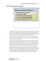
Step by Step Using the ISO Recorder Power Toy
Perform the following:
1. Locate the file you downloaded. It will have a name similar to cdrom-1.1b9.iso.
2. Place a blank CD in your CD burner, and then right-click the file and choose Copy
Image To CD from the menu, as shown in Figure 6.1.
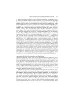
This will start the wizard. It verifies the source file and the destination CD burner, as shown in
Figure 6.2.
124 Chapter 6 • Wireless Operating Systems
Figure 6.1 Create a CD from an ISO Image Using the ISO Recorder Power Toy
Figure 6.2 ISO Recording Wizard Confirmation
www.syngress.com
308_Wi_Hack_06.qxd 9/30/04 3:49 PM Page 124
If you don’t have a blank CD in the burner, it won’t let you continue and you’ll need to cancel
the wizard and start over.The Recorder Properties should be set correctly, but if you have trouble
making a usable CD, you can use the settings to write the CD more slowly.
The CD writing process should be fast, even for a slow CD writer, as less than 10MB are written
to the 650MB capacity of the CD. Once the CD is finished, you’re ready to boot m0n0wall!
Creating a Compact Flash (CF) Card from Windows
To create a compact flash card version of m0n0wall, you’ll need the appropriate image file for your
target machine, as shown in Table 6.5.
WARNING: HARDWARE HARM
It’s vital to verify which device corresponds to your CF card, because you can easily overwrite
your (primary!) hard disk or other storage devices like USB memory keys with this utility. This
is discussed in detail in the next section, so pay attention and don’t skip ahead! We suggest
you remove any nonessential storage devices before attempting to write to your CF card.
The steps to safely write m0n0wall to your CF card are:
1. Download the appropriate image file.
2. Remove the CF card from your reader if it’s already inserted.
3. Run the physdiskwrite program.
4. Note the drives available.
5. Cancel the physdiskwrite.
6. Insert the CF card again.
7. Run the physdiskwrite program again.
8. Compare the drives available and confirm that the new drive appears to match the size and
other details of your CF card.
9. Confirm the copy to the CF card.
You should repeat steps 2 through 8 until you are certain your card is being recognized and that
you know which device it is.
The following detailed example will assume you’re using a PC Engines WRAP board, but the
strategy is identical for all CF-powered versions. Locate the file you downloaded. It should have a
name like wrap-1.1b9.img. Remove the CF card if it’s already inserted. Open a command prompt
using Start | Run and enter cmd (or command if you’re running Windows 98). Now you’ll run
physdiskwrite using Physdiskwrite wrap-1.1b9.img.
Immediately press Ctrl + C on the keyboard.This will generate output like that shown in
Figure 6.3.
www.syngress.com
Wireless Operating Systems • Chapter 6 125
308_Wi_Hack_06.qxd 9/30/04 3:49 PM Page 125
Some of the details to notice in this output are:
■
Two physical drives present, one of which is quite small.This is a USB memory key that is
inconvenient to remove.The other is the main hard disk for the system!
■
Four physical drives which return an error.These correspond to a multi-format card reader
with no cards in it.
Once you understand which disks correspond with which, you’re ready to insert the CF card and
run the same command again. Now the output will change to something similar to what’s shown in
Figure 6.4.
www.syngress.com
126 Chapter 6 • Wireless Operating Systems
Figure 6.3 Results of physdiskwrite with CF Card Removed
Figure 6.4 Results of physdiskwrite with CF Card Inserted
308_Wi_Hack_06.qxd 9/30/04 3:49 PM Page 126
Now there is a “PhysicalDrive3” that wasn’t there before.To double-check, the numbers should all
be smaller than “PhysicalDrive0,” which is the main hard disk for the computer.
You should repeat the physdiskwrite command several times with and without the card inserted
until you’re absolutely sure you’ll be writing to the correct disk. When you’re certain, you can enter
the number (3 in this example), and you’ll get a confirmation prompt. Press the Y key to continue, or
N to cancel, followed by the Enter key.The data will then be written to the CF card and a counter
showing the progress will be displayed. When writing is complete, a confirmation message will
appear, as shown in Figure 6.5.
If the write completes successfully, you’re now ready to put the CF card into your other com-
puter and turn it on!
Starting Your Standard PC
Now you have all the pieces together to start your standard PC.This section takes you step by step
through the process of turning your old PC doorstop into a modern firewall and access point.
Booting from the CD-ROM and a Blank Diskette
If you’re using a CD-ROM and diskette, be sure you first change the boot order for your computer.
You can make this change in your BIOS settings (described in a moment). It is important that the
blank floppy is available when you first boot m0n0wall from CD because it only checks for its exis-
tence at boot time and will only create an empty configuration file at boot time. It is tempting to not
change the boot order and to try and insert the floppy at “just the right time” after the CD has begun
booting, but we found that this is harder than just changing the boot order in the first place.
The boot order configuration is set in the BIOS of your computer and can be changed when it
first starts up by pressing a specific key such as F2 or the Delete key—it will usually tell you as it
boots.Then find the appropriate setup screen for setting the boot order. Figure 6.6 shows a typical
www.syngress.com
Wireless Operating Systems • Chapter 6 127
Figure 6.5 Completed Output of physdiskwrite
308_Wi_Hack_06.qxd 9/30/04 3:49 PM Page 127
configuration screen with CD-ROM Device at the top of the list, Hard-Disk Drive C: at the bottom,
and the 3.5” Diskette second.This means, of course, that if you don’t insert a floppy or CD, the com-
puter will boot normally from the hard disk.This is convenient for testing and configuration since
you can still boot from your hard disk if need be.This is handy if you’re testing m0n0wall on a dif-
ferent PC from the final machine you’ll use, or if you just need a firewall temporarily.
N
EED TO K
NOW…DEFAULT INTERFACE ASSIGNMENT
By default, m0n0wall will make the “first” Ethernet port the LAN port and use the second
port for WAN. If you can identify which is which, you can skip the console configuration
steps described in this section. For single board computers, the LAN port will be the eth0
port (see Table 6.6). For standard PCs, you can try first one port and then the other to see if
you get an IP address via DHCP. This will typically be 192.168.1.199. If you have a wireless
card installed, it will not be automatically enabled or assigned by m0n0wall. However, you
can do that from the web interface once you’ve logged in.
www.syngress.com
128 Chapter 6 • Wireless Operating Systems
Figure 6.6 A Typical Boot Order Configuration Screen
308_Wi_Hack_06.qxd 9/30/04 3:50 PM Page 128
Table 6.6 Single Board Computer Configuration Information
Eth0 Port when
facing ethernet
Product Default Serial Speed Interrupt Boot Key connectors
Soekris 19200 Control – P Right Hand Side
PC Engines WRAP 38400 S Right Hand Side
Assigning m0n0wall Network Interfaces
The m0n0wall console allows you to configure your network ports. If you’re using an older 10Mbps-
only network card, you may wish to assign that to your broadband DSL or Cable connection since it’s
unlikely to exceed 6Mbps, and then use your other 100Mbps card for the LAN connection. Figure
6.7 shows the console menu for m0n0wall.There are several options available, but the only thing you
need to do with the console is to map your network cards to their function—for instance, WAN or
LAN. If you have more network cards, you can either assign them here, or do so later using a Web
browser. For security, you can disable the console option completely once you’ve logged in via a Web
browser.
Choose option 1,“Interfaces: assign network ports” by pressing 1 and then the Enter key, as
shown in Figure 6.8. If your network cards are recognized successfully, you’ll see them listed under
the heading:“Valid interfaces are.” If you have them connected to an active device, their MAC address
will be followed by “(up)”.
www.syngress.com
Wireless Operating Systems • Chapter 6 129
Figure 6.7 The m0n0wall Console Setup Screen
308_Wi_Hack_06.qxd 9/30/04 3:50 PM Page 129
m0n0wall includes a convenient auto-detection mechanism that works by following these steps:
1. Unplug all cables from the ethernet cards in your standard PC.
2. Type A for auto-detection.
3. Plug in the ethernet cable for the interface it requests (LAN, WAN, or something else).
4. Repeat the steps for each interface.
Assuming your cables are wired correctly and the devices they’re connected to are running cor-
rectly, m0n0wall will detect that you plugged in the cable and then automatically assign that network
card to that function. Figure 6.9 shows the results.
www.syngress.com
130 Chapter 6 • Wireless Operating Systems
Figure 6.8 m0n0wall Assign Network Ports
308_Wi_Hack_06.qxd 9/30/04 3:50 PM Page 130
Once you’ve completed the network assignment, you can type Y and press Enter to save the data
and reboot your firewall. Once it’s restarted, you’re ready to continue with the rest of the configura-
tion using the browser.
Starting Your SBC
Installing m0n0wall on your single board computer (SBC) is similar to a standard PC, but you’ll need
to connect to your SBC via a serial port, rather than a keyboard and monitor, so you can access the
console.You should also install any radio card you wish to use, though it’s not necessary to connect
the antenna at this point. Figure 6.10 shows the PC Engines WRAP.1C board all ready to configure.
At the top left you can see the 8MB CF card with a new installation of the m0n0wall wrap distro, the
serial cable is connected at the bottom left, and the radio card is in the left-hand miniPCI slot. Power
is connected via the bottom right-hand connector.
www.syngress.com
Wireless Operating Systems • Chapter 6 131
Figure 6.9 m0n0wall Network Port Assignment Completed
308_Wi_Hack_06.qxd 9/30/04 3:50 PM Page 131
W
ARNING: HARDWARE HARM
Make sure the CF card is firmly in place. In the WRAP board, it’s easy to catch the raised lip
at the back of the card on the edge of the circuit board and not seat the card correctly. So
be careful.
Now you’ll need to run your terminal program and configure it for your SBC.The WRAP board
by default uses a baud rate of 38400.You can leave all the settings except baud rate at their default
values, which will usually be 8-bit data, no parity, 1 stop bit.Table 6.6 is a handy reference for boards
mentioned in this book. In Tera Term Pro, use Setup | Serial Port … to show the screen in Figure
6.11 and set the speed to 38400.
www.syngress.com
132 Chapter 6 • Wireless Operating Systems
Figure 6.10 A PC Engines WRAP.1C Board Ready to Configure
Figure 6.11 Tera Term Serial Port Setup
308_Wi_Hack_06.qxd 9/30/04 3:50 PM Page 132
Now you’re all ready. Apply power to your board.The exact sign on display screen will vary
depending on the board, but if you’ve set the speed correctly and your serial cable wiring is correct,
text will appear immediately after you apply power. When it does, immediately press the appropriate
key to interrupt the boot sequence. Again, each board will be different. As you can see in Table 6.6,
you press the S key for the WRAP board.You should then have output matching Figure 6.12.
Now you need to set the default baud rate to 9600 to match what m0n0wall uses for the console.
You do this by pressing 9, Q to quit, and then Y to save the changes.There will be a short pause and
then you’ll see gibberish on the screen as the board reboots to a different speed.
Remove power from the board, change your serial port speed again, and then re-apply power.
This time, don’t interrupt the boot process and you should eventually see the display shown in
Figure 6.13.
Wireless Operating Systems • Chapter 6 133
Figure 6.12 A PC Engines WRAP Board Powerup Menu
Figure 6.13 The m0n0wall Console Menu
www.syngress.com
308_Wi_Hack_06.qxd 9/30/04 3:50 PM Page 133
Once you see the m0n0wall console menu, you can assign the interfaces using the convenient
auto interface feature of m0n0wall.This works by following these steps:
1. Unplug all cables from the ethernet cards in your standard PC.
2. Type 1 to assign interfaces.
3. Type A for auto-detection.
4. Plug in the ethernet cable for the interface it requests (LAN, WAN, or something else).
5. Repeat the steps for each interface.
Assuming your cables are wired properly and the devices they’re connected to are running cor-
rectly, m0n0wall will detect that you plugged in the cable and automatically assign that network card
to that function. Because we also have an 802.11b radio card installed, it will also show up, with the
name wi0. Figure 6.14 shows the complete step-by-step interface assignment.
Once the interfaces are assigned, you should enter Y to save and reboot. Once it’s restarted, you’re
ready to continue with the rest of the configuration using a Web browser.
Configuring m0n0wall
Now that you have your interfaces assigned, you’re ready to log in to m0n0wall from your Web
browser. For best results, you’ll need a recent Web browser such as Internet Explorer or Mozilla using
the information in Table 6.7.
www.syngress.com
134 Chapter 6 • Wireless Operating Systems
Figure 6.14 Assigning the Network Interfaces and Radio Card in m0n0wall
308_Wi_Hack_06.qxd 9/30/04 3:50 PM Page 134
Table 6.7 m0n0wall Web Browser Login Information
Item Value
URL Address http://192.168.1.1
Login Name admin
Login Password mono (all lowercase, letter o, not number 0)
Type in the URL http://192.168.1.1, which should result in a standard browser login prompt.
The initial username is admin, and the default password is mono, which is all letters and all lowercase
(no zeroes).Table 6.7 summarizes this information. Once you’ve completed the login, you should see
the screen shown in Figure 6.15.
If you don’t see this screen, chances are your computer is not on the right subnet. Make sure
you’ve set your Internet connection settings to use DHCP and have verified that your computer’s IP
begins with 192.168.1.x. If it starts with something else, then you don’t have your main computer’s
network settings configured correctly. Look for a setting called DHCP or another option titled
“Obtain An IP Address Automatically.”
www.syngress.com
Wireless Operating Systems • Chapter 6 135
Figure 6.15 The m0n0wall Admin Interface
308_Wi_Hack_06.qxd 9/30/04 3:50 PM Page 135
This screen confirms the version and target machine (WRAP in this example) as well as how
long the firewall has been running.You can get back to this screen if you click the Status | System
link in the left-hand menu bar.
Before going much further, it’s best to get the time set correctly and to change the administrator
password.This is done by clicking System | General Setup, the first link in the left-hand menu bar.
Here you should change the Password and then scroll down to the Time Zone drop-down. Select the
closest city to your location. Leave the rest of the settings for now (even seemingly important ones
like the DNS servers). We’ll get back to them in a moment.
Be sure to click the Save button before continuing.
WAN—Get Online
If your main Internet connection happens to be DHCP-enabled, you may already be online.You can
verify this by opening a Web browser and pointing it to your favorite Web site. If that works, you can
skip this section and move on! If not, click the Interfaces | WAN link to open the WAN configura-
tion page.
Configuring the WAN interface is specific to your Internet service provider (ISP).You’ll need to
refer to the documentation that they provided to be sure of the type of connection parameters you
have. If you already have a computer online, then you can use that as a guide. It’s beyond the scope of
this book to provide all combinations that might be necessary to get your WAN port configured cor-
rectly, but here are some tips to get you going.
The commonest connection types are DHCP, Static, and PPPoE.Table 6.8 has some hints and
guidelines for recognizing and configuring each of these types. Note that some ISP connections,
notably cable-based systems, require you to reset the cable modem by turning it off, waiting a minute
and turning it on again, when you plug in a different ethernet device (since the cable modem will be
looking for the MAC address of the previously connected device). In some rare cases, you may need
to call your cable company to reset the MAC address.
Table 6.8 Common ISP Connection Types and Configuration Tips
Type How to Recognize Settings Required from ISP Comments
Static Usually very clearly IP address, subnet mask or Example:
communicated by ISP CIDR, gateway, and DNS IP: 123.3.24.67
as “static IP” servers Subnet: 255.255.255.0
Gateway: 123.3.24.1
DNS: 22.33.44.55,
22.33.46.55
DNS values are entered
on the System | General
Setup page
DHCP Usually nothing None typically; may require (none)
specified by ISP a specific hostname be set
www.syngress.com
136 Chapter 6 • Wireless Operating Systems
Continued
308_Wi_Hack_06.qxd 9/30/04 3:50 PM Page 136
Table 6.8 Common ISP Connection Types and Configuration Tips
Type How to Recognize Settings Required from ISP Comments
PPPoE ISP usually provides a Username, password If your computer cur-
setup disk along with rently has PPPoE in use,
a username and disable it before trying to
password. reconnect via m0n0wall
since it will no longer be
necessary.
m0n0wall uses Classless Inter-Domain Routing (CIDR) addressing instead of the older subnet
mask style. Common mappings are shown in Table 6.9. Use this as a guide for your static IP configu-
ration, and other subnet settings in this chapter.
Table 6.9 Common Subnet Mask–to-CIDR Conversions
Subnet Mask CIDR Equivalent
255.0.0.0 /8
255.255.0.0 /16
255.255.255.0 /24
255.255.255.224 /27
255.255.255.254 /31
After you enter the settings and click Save, you’ll need to restart m0n0wall as prompted by the
system, or by clicking Diagnostics to open the Diagnostics menu, and then choosing Reboot
System.This will take a minute or two.
You should then test your WAN connection before continuing. Click Diagnostics and then
Ping. Enter a hostname that you can normally reach and click the Ping button.The results should
look similar to those in Figure 6.16.
Wireless Operating Systems • Chapter 6 137
Figure 6.16 Results of a Ping Test
www.syngress.com
308_Wi_Hack_06.qxd 9/30/04 3:50 PM Page 137
If the ping is successful, then your WAN link is working. If it fails, then next try to ping a known
Internet address. For example, if you know your DNS or gateway address (provided by your ISP), you
could try pinging them. For instance, instead of filling the Host field with a web site name like
www.yahoo.com, as shown in Figure 6.16, you would use an IP address like 66.94.230.33. If an IP
address works but a text address won’t, then your DNS settings are incorrect or missing.
If ping fails for both text and numeric IP addresses, the next step is to check m0n0wall’s logs
under Diagnostics | System logs.The bottom of the log page contains the most interesting infor-
mation, as the first 20 to 30 lines are system startup information and are not relevant for WAN con-
figuration.The errors will vary by the type of ISP connection you have. Look for clues like error or
failed to help determine what is failing.
If you continue to have problems, search your ISP’s help pages or ask your ISP for assistance. It is
becoming common for households to have more than one computer (or other Internet-connected
devices). Most people use an Internet sharing device often called a home gateway or broadband
router (or something similar), which all require the same settings as your m0n0wall device.
LAN—Customizing for Your Network
Once your m0n0wall is on the Internet, you should be able to immediately use it from the same
computer you used to set up the m0n0wall configuration. By default, it will forward local traffic and
route the responses back to your computer.The basic LAN configuration is set using the Interfaces
| LAN screen as shown in Figure 6.17.The only option available is to set the LAN IP address of the
m0n0wall and the network mask length.
By default, the m0n0wall LAN IP address is set to 192.168.1.1, but you can choose any address or
subnet you desire.Assuming you have a private subnet (RFC 1918), you can safely pick any address
www.syngress.com
138 Chapter 6 • Wireless Operating Systems
Figure 6.17 The m0n0wall LAN Configuration
308_Wi_Hack_06.qxd 9/30/04 3:50 PM Page 138
range shown in Table 6.10. It’s common for a gateway device like the m0n0wall to run at the “.1”
address, so it’s recommended you do the same.
Table 6.10 Reserved Private IP Address Ranges
Network Range CIDR length Comment
0.0.0.0 to /8 A subnet of this is handy to type and remember—for
0.255.255.255 example, 10.10.10.1/24.
72.16.0.0 to /16 Less commonly used, so it may prove handy in
72.31.255.255 avoiding confusion with other networks.
92.168.0.0 to /24 The lower ranges are often used as default settings
92.168.255.255 for vendor equipment—for example, many home
LANs run on 192.168.0/24 or 192.168.1/24 subnets.
Once you make changes to the LAN IP, you’ll need to reboot your m0n0wall using the
Diagnostics | Reboot system menu, and then possibly restart all the computers on your LAN also
(or force a release/renew of their IP addresses).
Once you have the LAN configured to your satisfaction, you can plug the m0n0wall LAN port
into a hub or switch and multiple computers will be able to share the one Internet connection. Plug
an access point directly into the m0n0wall or into the hub and you’ll immediately have wireless access
as well.
The external access point is transparent to the m0n0wall and the rest of the network—it appears
to be another hub with one or more computers hooked up to it.Those wireless computers will still
use the m0n0wall to lease an IP address and receive NAT services for shared Internet access as well.
You’ll need to configure the access point via its configuration interface so that its management IP
address is on the same network as the m0n0wall. For example, if your m0n0wall is at 192.168.1.1,
then you might assign your wireless access point the address 192.168.1.2 so it doesn’t conflict.
You can either assign the AP an IP directly via its management interface (usually via a Web
browser), or you can use the DHCP static assignment feature of m0n0wall to allow it to retrieve its
setting via DHCP.To configure static DHCP addresses, go to the Services | DHCP menu. Scroll
down to the very bottom and click the + (plus) symbol on the right-hand side.You can then enter
the desired IP address (for instance, 192.168.1.2).Then find the MAC address of the device, usually
marked on the outside of the box, and enter that (say, 00:80:C8:AC:F8:64). And finally enter a
description such as Upstairs 802.11b Access Point. Click Save and you’ll see the entry at the
bottom of the DHCP table, as shown in Figure 6.18.
www.syngress.com
Wireless Operating Systems • Chapter 6 139
308_Wi_Hack_06.qxd 9/30/04 3:50 PM Page 139
You can also enter MAC addresses from your computers into this table so they’ll receive the same
IP each time they request one.You can check the m0n0wall DHCP logs at Diagnostics | DHCP
leases and then click the DHCP tab to see recent leases made to computers on your network.
Access Point—Turning on the Radio
If you have a wireless radio in your computer, now it’s time to turn it on so wireless users can also
access the Internet. (If you have an external access point you wish to use, simply plug it into the LAN
port as described in the previous section.)
If you have the menu item Interfaces | OPT1 then skip ahead. If you just installed the radio,
then you’ll need to add it via the small (assign) link to the right of the bold Interfaces item on the
menu. Click the + (plus) sign below and to the right of the table of interfaces. If the wireless card is
recognized and is the only new interface added, it will automatically create a new OPT1 entry and
assign the radio card, as shown in Figure 6.19.The radio card will typically be called wi0, for “wireless
zero,” whereas Ethernet interfaces are called sis0 or eth0, depending on their chipset.
www.syngress.com
140 Chapter 6 • Wireless Operating Systems
Figure 6.18 m0n0wall DHCP Lease Configuration
308_Wi_Hack_06.qxd 9/30/04 3:50 PM Page 140
Before rebooting as prompted, you can configure the wireless card so it will be active after the
reboot.
Click the newly created Interfaces | OPT1 menu item and enter the options as described in
Table 6.11.The bold values are different from the default settings.
Table 6.11 Wireless Interface Option Settings
Option Name Value Comments
Enable Optional 1 Checked Check this to turn on the radio when m0n0wall is
Interface restarted.
Description WLAN Change this to WLAN (Wireless LAN) to have this
appear elsewhere in the configuration pages
instead of the less obvious OPT1 name.
Bridge With none Bridging should be off if you wish to use advanced
features like captive portal.
IP Address 192.168.2.1/24 Enter a different, nonoverlapping, subnet other
than your LAN interface.
Mode hostap Also known as “access point” mode
Service Set Identifier 630.Camerana How your network will show up when someone
(SSID) scans for access points. Assuming you want people
to be able to find you, it’s best to provide some
contact info as the SSID, such as a street address,
phone number, e-mail, or Web site address. For pri-
vacy reasons, you may not wish to divulge this
information.
www.syngress.com
Wireless Operating Systems • Chapter 6 141
Figure 6.19 Newly Added OPT1 Radio wi0 Interface in m0n0wall
Continued
308_Wi_Hack_06.qxd 9/30/04 3:50 PM Page 141
Table 6.11 Wireless Interface Option Settings
Option Name Value Comments
Channel 6 Scan from your wireless computer to see what
channels are already in use and pick a different
one. Be aware that adjacent channels interfere, so
it’s best to choose between channels 1, 6, or 11, or
perhaps 1, 4, 7 and 11. Some countries allow
higher channels.
Enable Wired Equivalent Unchecked Enabling this too soon makes debugging bad set-
Privacy (WEP) tings much harder, so leave WEP disabled until you
verify that everything is working okay.
The completed screen is shown in Figure 6.20. Click Save when you’re done. Just one more page
of settings before its time to reboot.
After the wireless interface is configured and enabled, you need to set up DHCP to provide
addresses for computers connecting via wireless. Click the Services | DHCP menu link and you’ll
now find two tabs to choose from: the LAN tab that was always there, and a new WLAN tab (or
OPT1 if you chose not to rename it).Turn on the Enable DHCP Server On WLAN Interface
setting and set the range as desired. For example, a range from 192.168.2.100 to 192.168.2.199 is
www.syngress.com
142 Chapter 6 • Wireless Operating Systems
Figure 6.20 m0n0wall Wireless Configuration Settings Completed
308_Wi_Hack_06.qxd 9/30/04 3:50 PM Page 142
analogous to the default provided via DHCP on the LAN interface. On this same page, you can also
define any static IP-MAC mappings you’d like to enter (as described earlier in this chapter). Click
Save one final time and you’ll see Figure 6.21.
Choose the Diagnostics | Reboot system menu and click Ye s to restart with your new set-
tings. When it restarts, you should now have a working wireless network! Verify this by firing up your
wireless computer and scanning for available networks.You should see the SSID you specified and
your computer will have an IP address and appropriate parameters for DNS servers, gateway, and
subnet mask.
However, you still can’t use the Internet. For security reasons, the default firewall settings don’t
apply to new interfaces.You have to create a new rule that allows the WLAN interface to access the
WAN interface (or LAN interface if you wish LAN and WLAN computers to share files, for
example).
Click Firewall | Rules to see the LAN rule that already exists, as shown in Figure 6.22.
www.syngress.com
Wireless Operating Systems • Chapter 6 143
Figure 6.21 m0n0wall Wireless Interface DHCP Configuration
308_Wi_Hack_06.qxd 9/30/04 3:50 PM Page 143
Another rule is needed to allow WLAN access. It should look just like the existing LAN rule,
except replacing LAN with WLAN. Click the + (plus) sign on the bottom right below the existing
table to open the new rule screen shown in Figure 6.23.
www.syngress.com
144 Chapter 6 • Wireless Operating Systems
Figure 6.22 Default m0n0wall LAN Firewall Rules
Figure 6.23 The New Rule Screen
308_Wi_Hack_06.qxd 9/30/04 3:50 PM Page 144
Because this is a broad rule, only three fields need to be changed.
1. Interface should be changed from WAN to WLAN.
2. Protocol should be changed from TCP to any.
3. Change Source Type from any to WLAN subnet.
4. (Optional) Change Description to WLAN
-> any.
Click Save to create the rule and then click Apply Changes to start the rule working. Figure
6.24 shows the results.
After making the changes, reboot the firewall.You should now be able to surf successfully.
Congratulations, you have a working wireless access point that is extremely powerful and config-
urable!
Captive Portal—Requiring Sign On
Wireless access points are being installed in public spaces all over the world. Many of these are free for
“appropriate use,” where “appropriate” can vary dramatically. One convenient way to inform people
about the appropriate use is to show them the rules before they start using the connection.
The common solution for this is to redirect any incoming requests to a Web page that you design
and block all access until the user acknowledges the page by clicking a Continue button, or similar.
This is commonly termed a “captive portal.” Recent versions of m0n0wall provide captive portal sup-
www.syngress.com
Wireless Operating Systems • Chapter 6 145
Figure 6.24 m0n0wall WLAN Access Rules
308_Wi_Hack_06.qxd 9/30/04 3:50 PM Page 145
port and in this section you’ll learn how to turn it on. m0n0wall’s captive portal is evolving quickly,
so the following may not be exact, but the principles will remain unchanged.
Before you can configure captive portal, you need to:
■
Decide which interface you wish to make captive.You can’t be using bridged interfaces, so
for example, any wireless radio you have must be separated onto its own subnet running
DHCP (as described earlier in this chapter).
■
Design an HTML page that will be displayed before the user can continue.
m0n0wall also supports authenticated sign-in using the popular RADIUS protocol, in case you
only want to allow access to certain users.You’ll need a separate RADIUS server to use that feature.
A minimal HTML page to use for the portal is:
<html><body>
<center>
<h1>Welcome to my Captive Portal</h1>
<form method="post" action="">
<p>Click the Continue button to start surfing.</p>
<input name="accept" type="submit" value="Continue">
</form>
</center>
</body></html>
Save this as a file—for example, captiveportal.html. Note that you cannot use images in this Web
page as there is nowhere to store them in m0n0wall. When you’re done with the HTML, click
Services | Captive Portal to show the settings page. Change the settings as follows:
1. Check the Enable Captive Portal option.
2. Choose the desired interface—for example, WLAN (or OPT1).
3. Specify the HTML file to display for the portal page (for example, captiveportal.html)
4. Click Save.
The admin interface is exempt from the portal, so you’ll be able to continue viewing the admin-
istrative pages. If you open another Web browser, however, and go to your favorite Web site, you
should be greeted with the screen shown in Figure 6.25.
www.syngress.com
146 Chapter 6 • Wireless Operating Systems
308_Wi_Hack_06.qxd 9/30/04 3:50 PM Page 146
By clicking Continue, the Web site you were trying to visit will be displayed. All other Internet
access is blocked until the button is clicked, so if you’re used to opening your e-mail program before
opening a Web browser, you’ll find that the e-mail fails to work until you acknowledge the sign-in
page in a Web browser.
The captive portal configuration can be tweaked further. For example, you can
■
Decide which Web sites, if any, should be allowed through the portal (for example, the Web
site of a sponsoring company for a public hotspot).You can use this feature to add images to
your captive portal page.
■
Gather any computer MAC addresses that may bypass the portal (for instance, a Wi-Fi
phone or other device lacking a browser interface that needs outside access).This function-
ality is sometimes referred to as a “whitelist.”
These are entered under the Allowed IP Addresses and Pass-through MAC tabs of the Services |
Captive portal page.
You can monitor use of your captive portal with the Status | Captive portal page.This will let
you view what computers are currently using the system and the time of their most recent activity.
Finishing Off—Making a Backup
Last but not least, anytime you’ve configured m0n0wall to your satisfaction, make a backup of all the
configuration settings.This is fast and simple.All the settings are saved into a single file in XML
format.You can even edit the file with a text editor to make simple changes to most settings.
Click the Download Configuration button to save the settings, as shown in Figure 6.26.You
may wish to rename the file from config.xml to m0n0config.xml or something even more mean-
ingful to help retrieve it later.The same configuration file works across all m0n0wall platforms, which
is handy when upgrading, say, from an old PC to a compact, quiet single board computer.
www.syngress.com
Wireless Operating Systems • Chapter 6 147
Figure 6.25 The Captive Portal Page in Action
308_Wi_Hack_06.qxd 9/30/04 3:50 PM Page 147
Under the Hood: How the Hack Works
m0n0wall is a fascinating firewall and access point distro. It is unique in design because it is based on
FreeBSD, but all the configuration and administration is powered by a high-level PHP scripting lan-
guage. PHP is designed for building Web pages, and is well suited to making the powerful configura-
tion screens that m0n0wall provides. However, it is unusual to also use PHP to create and manage the
myriad of files required by BSD’s many programs that run behind the scenes to provide m0n0wall’s
rich functionality.
It’s possible to get “behind the scenes” of m0n0wall with some special hooks provided for devel-
opers and the technically curious. For example, if you enter the URL: http://192.168.1.1/
status.php, you’ll see the output of many of the underlying BSD programs.
Another powerful tool is found at: http://192.168.1.1/exec.php.This allows you to execute any
FreeBSD command and see the output, or to upload or download a file. Using these tools you can
modify the underlying files for m0n0wall while it is running. More details can be found in the hackers
guide on the m0n0wall Web site at />Pebble—Powerful, Raw, Complete
The Pebble distro is the creation of Terry Schmidt, a talented member of NYCWireless. It is available
at their Web site: />The Pebble distro is a version of the Woody release of Debian Linux which has been stripped
down and modified to run on a 64MB compact flash card. It stands apart from other distros in several
key ways:
www.syngress.com
148 Chapter 6 • Wireless Operating Systems
Figure 6.26 Back Up and Restore All m0n0wall Settings
308_Wi_Hack_06.qxd 9/30/04 3:50 PM Page 148