Modelling with AutoCAD 2002 Episode 2 ppt
Bạn đang xem bản rút gọn của tài liệu. Xem và tải ngay bản đầy đủ của tài liệu tại đây (1.14 MB, 30 trang )
Task
1 Save the coordinate exercise if required, but we will not refer to it again
2 With File-Open recall your 3DSTDA3 template file
3 Menu bar with View-Display-UCS icon and ensure:
a) On and origin active – tick
b) Properties and set icon to your preference 2D or 3D
4 Menu bar with View-3D Views-SE Isometric
5 Menu bar with View-Zoom-Scale and enter a factor of 0.75
6 The WCS icon should be positioned at left vertex of the border
7 Save this layout as:
a) the 3DSTDA3.dwt template file and replace the existing template file. Enter a
suitable template description
b) the 3DSTDA3.dwg drawing file, overwriting the existing file
8 This will allow the template file to opened in 3D with the icon always ‘set’ to the origin
position.
Summary
1 There are two coordinate systems:
a) the world coordinate system WCS
b) the user coordinate system UCS
2 Each system has its own icon
3 The WCS is a fixed system, the origin being at 0,0,0
4 The WCS icon is ‘standard’ and does not alter in appearance. The WCS icon is denoted
with the letter W
5 The UCS system allows the user to define the origin, either as a point on the screen or
referenced to an existing object
6 The UCS icon alters in appearance dependent on the viewpoint
7 The UCS icon can be rotated about the three axes
8 The UCS current position can be saved and recalled
9 The user can set a 2D or 3D UCS icon style
10 3D coordinate input can be:
a) Cartesian, e.g. 10,20,30
b) Cylindrical, e.g. 10<20,30
c) Spherical, e.g. 10<20<30
11 Both absolute and relative modes of input are possible with the three ‘types’ of
coordinates, e.g.
a) absolute cylindrical: 100<200,50
b) relative cylindrical: @100<200,50
12 3D coordinate input can be relative to the current UCS position or to the WCS, e.g.
a) 100,200,150 for UCS entry
b) *100,200,150 for WCS entry
13 It is recommended that 3D coordinate input is relative to the current UCS
position.
The UCS and 3D coordinates 23
modelling with AutoCAD.qxd 17/06/2002 15:37 Page 23
Creating a 3D
wire-frame model
In this chapter we will create a 3D wire-frame model and use it to:
a) investigate how the UCS can be set and saved
b) add ‘objects’ and text to the model ‘planes’
c) modify the model
Getting started
1 Open your 3DSTDA3 template file to display:
a) a 3D viewpoint with the black border
b) the WCS icon at the left vertex of the border
2 Ensure layer MODEL is current and refer to Fig. 4.1
3 Display the Draw, Modify and Objects Snap toolbars
Chapter 4
Figure 4.1 Construction of the wire-frame model 3DWFW.
modelling with AutoCAD.qxd 17/06/2002 15:37 Page 24
Creating the wire-frame model
1 To create the base of the model – fig(a), select the LINE icon and draw:
Start point 50,50 <R> pt1
Next point @200,0 <R> pt2
Next point @0,120 <R> pt3
Next point @–200,0 <R> pt4
Next point close
2 The top plane – fig(b) is also created from lines, so with the LINE icon draw:
Start point Intersection icon of pt4
Next point @0,0,100 <R> pt5
Next point @200,0,0 <R> pt6
Next point @0,–40,0 <R> pt7
Next point @–200,0,0 <R> pt8
Next point Intersection icon of pt5 pt5
Next point right-click and pick Enter
3 If you cannot ‘see’ the complete model, then menu bar with View-Zoom-Scale and
enter a scale factor of 0.9
4 To create the front vertical plane – fig(c), select the LINE icon and draw:
Start point Intersection icon of pt1
Next point @0,0,45 <R> pt9
Next point @60,0,0 <R> pt10
Next point Intersection icon of pt2
Next point right-click and Enter
5 With the LINE icon draw:
Start point Intersection of pt9
Next point Intersection of pt8 then right-click/enter
6 LINE icon again:
Start point Intersection of pt10
Next point Perpendicular to line 78 pt11
Next point right-click and Enter
and first sloped plane created – fig(d)
7 To create the second sloped plane – fig(e), select the LINE icon and draw:
Start point Intersection of pt10
Next point @0,80,0 <R> pt12
Next point Perpendicular to line 23 pt13
Next point right-click and Enter – fig(e)
8 To completing the model, three lines require to be added, so with the LINE icon draw:
a) from pt3 to pt6
b) from pt7 to pt13
c) from pt11 to pt12
9 The completed model is displayed in fig(f) on ‘its base’, i.e. the black border.
10 At this stage save the model as a drawing file with the name C:\MODR2002\3DWFM
11 Note
The model has been created using 3D coordinate input with the WCS, i.e. no attempt
has been made to use the UCS. This is a perfectly valid method of creating wire-frame
models, but difficulty can be experienced if objects and text have to be added to the
various ‘surfaces’ of the model when the coordinates need to be calculated. Using the
UCS usually overcomes this type of problem.
Creating a 3D wire-frame model 25
modelling with AutoCAD.qxd 17/06/2002 15:37 Page 25
Moving around with the UCS
To obtain a better understanding of the UCS and how it is used with 3D models, we will
use the created wire-frame model to add some objects and text. The sequence is quite
long but it is important that you persevere and complete the exercise. Both menu bar
and keyboard entry methods will be used to activate the UCS command.
1 Open the wire-frame model C:\MODR2000\3DWFM or continue from the previous
exercise. This model has the WCS icon at the black border origin point – the left vertex
2 Menu bar with View-Display-UCS Icon and:
a) On and Origin both active (tick)
b) select Properties and set a 2D UCS icon style
3 Refer to Fig. 4.2
4 PAN the layout until the lower black border vertex is near the lower edge of the screen.
This will allow us to ‘see’ any UCS movements more clearly
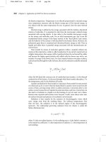
5 Menu bar with Tools-New UCS-Origin and:
prompt Specify new origin point<0,0,0>
respond Intersection icon and pick pt1
and a) icon ‘moves’ to selected point – fig(a)
b) it is a UCS icon – no W
c) it is at the origin – the +
note if the icon does not move to the selected point, menu bar with View-Display-
UCS Icon and pick Origin
26 Modelling with AutoCAD 2002
Figure 4.2 Investigating the UCS and adding objects and text to 3DWFW.
modelling with AutoCAD.qxd 17/06/2002 15:37 Page 26
6 Now that the icon has been repositioned at point 1, we want to save its ‘position’ for
future recall, so at the command line enter UCS <R> and:
prompt Enter an option
enter S <R> – the save option
prompt Enter name to save current UCS
enter BASE <R>
7 Make layer OBJECTS current and use the LINE icon to draw:
Start point 100,25,0 <R>
Next point @0,30,0 <R>
Next point 145,40,0 <R>
Next point close
8 Make layer TEXT current and menu bar with Draw-Text-Single Line Text and:
a) start point: 60,10,0
b) height: 10 and 0 rotation
c) text item: BASE
9 The line objects and text item are added as fig(a)
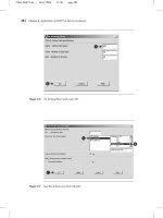
10 Menu bar with Tools-New UCS-Origin and:
prompt Specify new origin point<0,0,0>
respond Intersection icon and pick pt8
and icon ‘jumps’ to the selected point – fig(b)
11 At the command line enter UCS <R> and:
prompt Enter an option
enter S <R> – the save option
prompt Enter name to save current UCS
enter TOP <R>
12 With layer OBJECTS current draw a circle with centre: 60,20 and radius: 15
13 With layer TEXT current, add single line text using:
a) start point: 85,10
b) height: 10 with 0 rotation
c) text item: TOP
14 Using the COPY icon:
a) select objects: pick the circle then right-click
b) base point: Center icon and pick the circle
c) second point: enter @0,0,–100 <R> – fig(b)
d) question: why these coordinates?
15 Menu bar with Tools-UCS-3Point and:
prompt Specify new origin point<0,0,0>
respond Intersection icon and pick pt2
prompt Specify point on positive portion of the X-axis
respond Intersection icon and pick pt3
prompt Specify point on positive-Y portion of the UCS XY plane
respond Intersection icon and pick pt10
16 The UCS icon will move to point 2 and be ‘aligned’ on the sloped surface as fig(c)
17 Note
The 3 point option of the UCS command is ‘asking the user’ for three points to define
the UCS icon orientation, these being:
first prompt the origin point
second prompt the direction of the X axis
third prompt the direction of the Y axis
Creating a 3D wire-frame model 27
modelling with AutoCAD.qxd 17/06/2002 15:37 Page 27
18 Save this UCS position by entering at the command line UCS <R> then S <R> and:
prompt Enter name to save current UCS
enter SLOPE1 <R>
19 With layer OBJECTS current use the LINE icon to draw:
Start 15,100,0
Next @50,0,0
Next 40,30,0
Next close
20 With layer TEXT current, add a single text item using:
a) start point: centred on 10,110
b) height: 10 with 0 rotation
c) item: SLOPE1 – fig(c)
21 At command line enter UCS <R> and:
prompt Enter an option
enter R <R> – the restore option
prompt Enter name of UCS to restore
enter BASE <R>
and icon restored to the base point as fig(a)
(The restore option is used extensively with UCS’s)
22 Menu bar with Tools-New UCS-X and:
prompt Specify rotation angle about X axis
enter 90 <R>
and icon displayed as fig(d)
23 At command line enter UCS <R> then S <R> for the save option and FRONT <R>
as the UCS name to save
24 With layer TEXT current add an item of text with:
a) start point: 25,20
b) height: 10 with 0 rotation
c) text: FRONT – fig(d)
25 Menu bar with Tools-New UCS-3 Point and:
prompt Specify new origin point
respond Intersection icon and pick pt7
prompt Specify point on positive portion of the X-axis
respond Intersection and pick pt11
prompt Specify point on positive-Y portion of the UCS XY plane
respond Intersection icon and pick pt13
26 The UCS icon will be aligned as fig(e)
27 Save this UCS position as VERT1 – easy? (UCS-S-VERT1)
28 With layer TEXT current add a text item with:
a) start point: 120,50
b) height: 10
c) rotation: –90
d) text: VERT1 – fig(e)
29 Restore UCS BASE and the model will be displayed as fig(f)
30 Make layer MODEL current and save the drawing at this stage as C:\MODR2000\
3DWFM updating the original wire-frame model.
28 Modelling with AutoCAD 2002
modelling with AutoCAD.qxd 17/06/2002 15:37 Page 28
Modifying the wire-frame model
To further investigate the UCS we will modify the wire-frame model, so refer to Fig. 4.3 and:
1 3DWFM still on the screen? – if not open the drawing file
2 Layer MODEL current with UCS BASE – fig(a)
3 Select the CHAMFER icon from the Modify toolbar and:
a) set both chamfer distances to 30
b) chamfer lines 7–11 and 7–13
c) chamfer lines 5–6 and 6–3
4 Now add two lines to complete the ‘chamfered corner’ and erase the unwanted original
corner line – fig(b).
5 Restore UCS VERT1 and note its position – fig(c)
6 Draw two circles:
a) centre at 80,0,0 with radius 30
b) centre at 80,0,–40 with radius 30 – fig(c)
7 Using the TRIM icon from the Modify toolbar:
a) trim the two circles ‘above’ the model
b) trim the two lines ‘between’ the circles – fig(d)
8 Move the TOP text item from: ENDPOINT of pt5, by: @80,0
9 Draw in the two lines on the top plane and restore UCS BASE.
10 The modified model is now complete – fig(e)
11 Save the model as C:\MODR2000\3DWFM updating the existing model drawing
12 Note
The user should realise that the UCS is an important concept with 3D modelling. Indeed
I would suggest that 3D modelling would be very difficult (if not impossible) without it.
Creating a 3D wire-frame model 29
Figure 4.3 Modifying the 3DWFM model.
modelling with AutoCAD.qxd 17/06/2002 15:37 Page 29
Task 1
1 The wire-frame model has eleven flat planes and one ‘curved surface’. We have set and
saved UCS positions for five of these planes – BASE, TOP, SLOPE1, FRONT and VERT1.
2 You now have to set and save the other six flat UCS positions, i.e. one for each surface
and add an appropriate text item to that surface.
3 My suggestions for the UCS name and text item are LEFT, RIGHT, REAR, SLOPE2,
SLOPE3 and VERT2 but you can use any names that you consider suitable.
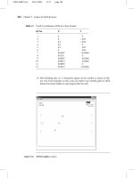
4 Figure 4.4 displays the complete wire-frame model with text added to every plane (with
the exception of the curved surface) using the UCS positions I ‘set’ Realise that your
additional text may differ in appearance from mine. This is acceptable as your UCS
positions may be ‘set’ different from mine
5 When complete, remember to save as MODR2002\3DWFM as it will be used in other
chapters.
Task 2
1 Restore UCS BASE – should be current?
2 With the MOVE command:
a) window the complete model then right-click
b) base point: 0,0
c) second point: @100,100
3 The complete model moves as expected, but do the set UCS’s move with the model? This
can be a nuisance when moving models. The UCS is ‘not tied’ to a specific model, it is
ONLY A POSITION ON THE SCREEN
4 This exercise is now complete. Do not save the changes.
Figure 4.4 The complete 3D wire-frame model (3DWFM) with text added to every plane.
30 Modelling with AutoCAD 2002
modelling with AutoCAD.qxd 17/06/2002 15:37 Page 30
Summary
1 Wire-frame models are created by coordinate input and by referencing existing objects
2 Both the WCS and UCS entry modes can be used, but I would recommend:
a) use the WCS to create the basic model outline
b) use the UCS to modify and add items to the model
3 It is strongly recommended that a UCS be set and saved for every surface on a wire-
frame model.
Assignments
Creating wire-frame models at this stage is important as it allows the user to:
a) use 3D coordinate entry with the WCS and/or the UCS
b) set and save different UCS positions
c) become familiar with the concept of 3D modelling
I have included two 3D wire-frame models which have to be created. The suggested
approach is:
1 Open your 3DSTDA3 standard file – template or drawing
2 Complete the model with layer MODEL current, starting at some convenient point, e.g.
50,50,0. Use WCS entry and add one ‘plane’ at a time
3 Save each completed model as a drawing file in your named folder with a suitable name,
e.g. C\MODR2002\ACT2, etc.
4 Note:
a) do not attempt to add dimensions
b) do not attempt to display the two models on ‘one screen’ – you will soon be able to
achieve this for yourself.
c) these models will be used for later assignments, so ensure they are saved
d) use your discretion for any sizes not given
The activities concern our master builder MACFARAMUS, and you have to create 3D
wire-frame models of two of his famous shaped blocks. It is not known how these blocks
were used, i.e. in road building, structures, plazas etc, but they allow us to create wire-
frame models.
Activity 2: MACFARAMUS’s shaped block 1
A relatively simple wire-frame model to create. I suggest that you construct it in a similar
manner to the worked example, i.e. create the base, then the front vertical plane. The
‘back’ vertical plane can be drawn or copied from the front plane. The top and slopes
are then easy to complete. When finished, save as MODR2002\ACT2
Activity 3: MACFARAMUS’s shaped block 2
This shaped block is slightly more difficult due to the curves. Create the basic shape as
two rectangular blocks, then add four circles, using an obvious ‘corner point’ as the circle
centre. The circles and lines can then be trimmed ‘to each other’, but the UCS position
is important. When complete, save as MODR2002\ACT3
Creating a 3D wire-frame model 31
modelling with AutoCAD.qxd 17/06/2002 15:37 Page 31
The UCS
The UCS is one of the basic 3D draughting ‘tools’ and it has several commands associated
with it. Although it was used in the previous chapter, we will now investigate in more detail:
a) setting a new UCS position
b) moving the UCS
c) the UCS and UCS II toolbars
d) the UCS dialogue box
e) Orthographic UCSs
f) UCS specific commands
Getting started
1 Open your MODR2002\3DWFM model from the previous chapter. This model has several
blue objects with several saved UCS positions and is ‘positioned’ on the black ‘sheet border’
2 Restore the UCS BASE – probably is current?
3 Layer MODEL current and freeze layer TEXT. Refer to Fig. 5.1 which does not display
the black sheet border. This is for clarity only.
Chapter 5
Figure 5.1 The UCS (NEW) options exercise.
modelling with AutoCAD.qxd 17/06/2002 15:37 Page 32
Setting a new UCS position
The user can set a new UCS position from the menu bar with Tools-New UCS or by
entering UCS <R> then N <R> at the command line. Both methods give the user
access to the same options although the selection order differs. The menu bar options
are displayed as:
World/Object/Face/View/Origin/ZAxis Vector/3 Point/X/Y/Z
The following is an explanation of these UCS option:
World
1 This option restores the WCS setting irrespective of the current UCS position. It is the
default AutoCAD setting.
2 At the command line enter UCS <R> then W <R> to display the WCS icon on the
sheet border at the left vertex as fig(a)
Origin
1 Used to set a new origin point. The user specifies this new origin point by:
a) picking any point on the screen
b) coordinate entry
c) referencing existing objects
2 When used, the UCS icon is positioned at the selected point if the UCS Icon display is
set to Origin. This option has been used in previous exercises.
3 Menu bar with Tools-New UCS-Origin and:
prompt Specify new origin point<0,0,0>
respond Intersection icon and pick ptA
and icon positioned as fig(b)
Z Axis Vector
1 Defines the UCS position relative to the Z axis, the user specifying:
a) the origin point
b) any point on the Z axis
2 Menu bar with Tools-New UCS-Z Axis Vector and:
prompt Specify new origin point
respond Intersection icon and pick ptB
prompt Specify point on positive portion of Z-axis
respond Intersection icon and pick ptC – fig(c)
3 The icon will be aligned with:
a) the X axis along the shorter base left edge
b) the Y axis along the front left vertical edge
c) the Z axis along the line BC
The UCS 33
modelling with AutoCAD.qxd 17/06/2002 15:37 Page 33
3 Point
1 Defines the UCS orientation by specifying three points:
a) the actual origin point
b) a point on the positive X axis
c) a point on the positive Y axis
2 Menu bar with Tools-New UCS-3 Point and:
prompt Specify new origin point
respond Intersection of ptB
prompt Specify point on positive portion of the X-axis
respond Intersection of ptC
prompt Specify point on positive-Y portion of the UCS XY plane
respond Intersection of ptD – icon as fig(d)
3 This is a very useful option especially if the icon is to be aligned on sloped surfaces. It
is probably my preferred method of setting the UCS.
Object
1 Aligns the icon to an object, e.g. a line, circle, polyline, item of text, dimension, block etc.
2 Menu bar with Tools-New UCS-Object and:
prompt Select object to align UCS
respond pick any point on circle on top surface
3 The icon is aligned as fig(e) with:
a) the origin at the circle centre point
b) the positive X axis pointing towards the circumference of the circle at the point
‘picked’ by the user
View
1 Aligns the UCS so that the XY plane is always perpendicular to the view plane.
2 Menu bar with Tools-New UCS-View
3 The UCS icon will be displayed as fig(f) and is similar to the traditional 2D icon?
4 This is a useful UCS option as it allows 2D text to be added to a 3D drawing – try it for
yourself.
X/Y/Z
1 Allows the UCS to be rotated about the entered axis by an amount specified by the user
2 Make UCS BASE current
3 Menu bar with Tools-New UCS-X and:
prompt Specify rotation angle about the X axis
enter 90 <R> – fig(g)
4 Menu bar with Tools-New UCS-Y and:
prompt Specify rotation angle about the Y axis
enter –90 <R> – fig(h)
5 Menu bar with Tools-New UCS-Z and:
prompt Specify rotation angle about the Z axis
enter –90 <R> – fig(i)
34 Modelling with AutoCAD 2002
modelling with AutoCAD.qxd 17/06/2002 15:37 Page 34
Face
1 Aligns the UCS with a selected solid model face. This option cannot be used with 3D wire-
frame models.
2 Restore UCS BASE
3 Menu bar with Tools-New UCS-Face and:
prompt Select face of solid object
respond pick any line of the top plane
prompt A 3D solid must be selected
No solids detected
Apply
An option which allows the user to apply the current UCS setting to a specific viewport.
We will use this option in later chapters, but not yet.
Moving a UCS
A selection which allows the user to move the UCS to a new origin position, the UCS
icon retaining both its orientation and name. Refer to Fig. 5.1 and:
1 UCS restored to BASE
2 Menu bar with Tools-Move UCS and:
prompt Specify new origin point or [Zdepth]
respond Intersection icon and pick ptA
and icon moved to point A and retains the name BASE
3 Restore UCS TOP
4 At the command line enter UCS <R> and:
prompt Enter an option [New/Move/
enter M <R> – the move option
prompt Specify new origin point or [Zdepth]
respond Intersection icon and pick ptC
and icon moves to point C and retains the name TOP
5 Restore UCS FRONT
6 Menu bar with Tools-Move UCS and:
prompt Specify new origin point or [Zdepth]
enter Z <R> – the Z depth option
prompt Specify Zdepth<0>
enter –120 <R>
and icon moved to ‘back of model’ and retains name FRONT
7 Note:
a) This UCS command should be used with caution as the user may not want a named
UCS to be ‘repositioned’
b) I never use this command. If I want to reposition the UCS, I use the origin option
c) Do not save the drawing, as you will saved these moved UCS’s
8 Task
Reset the three moved UCS’s to their original positions, i.e. BASE, TOP and FRONT
The UCS 35
modelling with AutoCAD.qxd 17/06/2002 15:37 Page 35
Other UCS options
The new UCS options are available from the command line but the menu bar selection
Tools-New UCS is the usual method of activating the command. The command line has
other UCS options available for selection, these being:
Prev
1 Restores the previously ‘set’ UCS position and can be used to restore the last 10 UCS
positions.
2 The command is activated from the command line by entering UCS <R> then P <R>
and can be used continually until the command line displays ‘no previous coordinate system
saved’.
Restore
1 Allows the user to restore a previously saved UCS position but the names of the saved
UCS’s must be remembered (This will be modified shortly). This option has been used
in our examples
2 At the command line enter UCS <R> then R <R> and:
prompt Enter name of UCS to restore or [?]
enter TOP <R>
then restore UCS BASE
Save
1 Allows the user to save a UCS position for future recall. It should be used every time a
new UCS has been defined.
2 The option is activated from the command line with UCS <R> then S <R> and the
user can enter any name for the UCS position.
Del
1 Entering UCS <R> then D <R> prompts for the UCS name to be deleted.
2 The default is none. Use with care!
?
1 The query option which will list all saved UCS positions
2 At the command line enter UCS <R> then ? <R> and:
prompt Enter UCS name(s) to list<*>
respond press the RETURN key
prompt AutoCAD Text Window with:
Current UCS Name: BASE
Saved Coordinate systems
and Details about all the saved UCS’s, their origin point and their X,Y and Z axes
orientation
respond cancel the window
36 Modelling with AutoCAD 2002
modelling with AutoCAD.qxd 17/06/2002 15:37 Page 36
The UCS toolbar
All the UCS options have so far been activated by keyboard entry with UCS <R> or
from the menu bar with Tools. The only reason for this is that I think it easier for the
user to understand what option is being used. The UCS options can also be activated in
icon form from the UCS and UCS II toolbars – Fig. 5.2. The toolbars have no icon selection
for the orthographic options or for Restore, Save, Delete or for query (?), although these
can easily be activated by selecting the actual UCS icon. An additional icon in both the
UCS and UCS II toolbars is Display UCS Dialog, while the UCS II toolbar allows saved
UCS’s to be made current, i.e. restored.
The user now has three methods of activating the various UCS options, these being:
a) from the menu bar
b) by command line entry
c) in icon form from the appropriate toolbar
It is user preference as to what method is used.
The UCS 37
Figure 5.2 The UCS and UCS II toolbars.
World UCS
UCS Previous
Display UCS Dialog
UCS
Origin UCS
Z Axis Vector UCS
3 Point UCS
X Axis Rotate UCS
Object UCS
Face UCS
View UCS
Apply UCS
Z Axis Rotate UCS
Y Axis Rotate UCS
Saved UCS’s
Display UCS dialog
Move UCS
modelling with AutoCAD.qxd 17/06/2002 15:37 Page 37
The UCS dialogue box
The UCS dialogue box can be activated by three different methods:
a) from the menu bar with Tools-Named UCS
b) by selecting the Display UCS dialog icon from either the UCS or UCS II toolbar
c) by entering UCSMAN <R> at the command line
When activated, the dialogue box allows the user three tab selections, these being:
a) Named UCSs – the default
b) Orthographic UCSs
c) Settings
To demonstrate using the UCS dialogue box:
1 Ensure the 3DWFM is displayed with UCS BASE current
2 Menu bar with Tools-Named UCS and:
prompt UCS dialogue box
with three tab selections and Named UCSs tab active
and a) a list of saved UCS names for the model
b) a World and Previous selection option
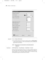
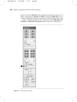
respond 1. pick Top
2. pick Set Current – Fig. 5.3
3. pick OK
2 The model will be displayed with the icon at the TOP setting
3 Use the Named UCS tab of the UCS dialogue box to set current some other saved UCS
positions
4 Set UCS BASE current
38 Modelling with AutoCAD 2002
Figure 5.3 The UCS dialogue box – Named UCS tab.
modelling with AutoCAD.qxd 17/06/2002 15:37 Page 38
5 Activate the UCS dialogue box and:
prompt UCS dialogue box – Named UCS tab active
respond 1. pick TOP and it becomes highlighted
2. right-click the mouse
prompt shortcut menu
with selections for: Set Current, Rename, Delete, Details
respond 1. pick Rename
2. enter new name: ABOVE <R>
3. pick Set Current
4. pick OK
6 The UCS will be displayed in the ‘old top position’
7 Now:
a) rename the ABOVE UCS to TOP again
b) make UCS BASE current
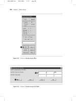
8 Activate the UCS dialogue box and pick the Settings tab and:
prompt Settings tab – Fig. 5.4
with 1. UCS icon settings for ON and ORIGIN – both active
2. UCS settings for viewports and plan
respond note the settings then pick Cancel
9 Note
a) The UCS icon settings from the dialogue box are the same as the menu bar selection
of View-Display-UCS Icon-On/Origin
b) The other Settings options will be discussed in later chapters
The UCS 39
Figure 5.4 The UCS dialogue box – Settings tab.
modelling with AutoCAD.qxd 17/06/2002 15:37 Page 39
Setting an orthographic UCS
This allows the user to restore six preset UCS positions, the orientation being set relative
to a saved UCS. Refer to Fig. 5.5 and:
1 Ensure the 3DWFM is displayed with the saved UCSs
2 Restore UCS SLOPE1 current – fig(a)
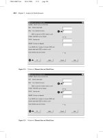
3 Activate the UCS dialogue box with the Orthographic UCS tab active and:
prompt UCS dialogue box – Orthographic tab display
respond 1. scroll at Relative to
2. pick BASE
3. at Current UCS Name, pick TOP
4. pick Set Current – Fig. 5.6
5. pick OK
and icon displayed as fig(b)
4 With the Orthographic tab of the UCS dialogue box, set Bottom current relative to BASE
– fig(c)
5 Menu bar with Tools-Orthographic UCS-Left to display the icon as fig(d)
40 Modelling with AutoCAD 2002
Figure 5.5 The Orthographic UCS options exercise relative to BASE with UCS SLOPE1 current.
modelling with AutoCAD.qxd 17/06/2002 15:37 Page 40
6 At the command line enter UCS <R> and:
prompt Enter an option [New/Move/orthoGraphic/
enter G <R> – the orthographic option
prompt Enter an option [Top/Bottom/Front/
enter R <R> – the right orthographic UCS option
and the icon will be displayed as fig(e)
7 With the menu bar Tools-Orthographic UCS sequence, select relative to BASE:
a) FRONT current – fig(f)
b) BACK current – fig(g)
8 Activate the Orthographic tab of the UCS dialogue box and:
a) set relative to SLOPE1
b) activate the six orthographic UCS positions
c) note the orientation of the UCS with each orthographic name
d) restore UCS BASE
9 This exercise with the UCS dialogue box is now complete.
10 Note
The menu bar sequence Tools-Orthographic UCS-Presets will display the
Orthographic tab of the UCS dialogue box.
UCS specific commands
The UCS has several specific commands associated with it. At this stage, we will only
investigate:
a) the PLAN command
b) the UCSFOLLOW system variable.
The UCS 41
Figure 5.6 The UCS dialogue box – Orthographic tab active.
modelling with AutoCAD.qxd 17/06/2002 15:37 Page 41
Plan
Plan is a command which displays any model perpendicular to the XY plane of the
current UCS position.
1 Ensure the 3DWFM is displayed with UCS BASE current
2 Refer to Fig. 5.7
3 At the command line enter PLAN <R> and:
prompt Enter an option [Current ucs/Ucs/World] <Current>
enter <R> i.e. accept the Current UCS default
4 The screen will display the model as a plan view – fig(a). This view is perpendicular to
the current UCS setting (BASE) and is really a ‘top’ view in orthogonal terms
5 Restore UCS FRONT – pencil icon?
6 Menu bar with View-3D Views-Plan View-Current UCS and the model will be
displayed as fig(b). This is a plan view to the current UCS FRONT and is a ‘front’ view
in orthogonal terms
7 Menu bar with View-3D Views-Plan View-Named UCS and:
prompt Enter name of UCS
enter SLOPE1 <R>
8 The model will be displayed as a plan to the UCS SLOPE1 setting as fig(c)
9 At the command line enter PLAN <R> and:
prompt Enter an option [Current ucs/Ucs/World]<Current>
enter U <R> – the Ucs option
prompt Enter name of UCS
enter VERT1 <R>
42 Modelling with AutoCAD 2002
Figure 5.7 The PLAN command with 3DWFM.
modelling with AutoCAD.qxd 17/06/2002 15:37 Page 42
10 The model display is as fig(d) i.e. a plan view to the UCS setting VERT1. This display
should be upside-down – why?
11 Finally restore UCS BASE and menu bar with View-3D Views-SE Isometric to return the
original model display.
UCSFOLLOW
UCS FOLLOW is a system variable which controls the screen display of a model when
the UCS position is altered. The variable can only have the values of 0 (default) or 1 and:
a) UCSFOLLOW 0: no effect on the display with UCS changes
b) UCSFOLLOW 1: automatically generates a plan view when the UCS is altered
1 Original 3D display with UCS BASE on the screen?
2 At the command line enter UCSFOLLOW <R> and:
prompt Enter new value for UCSFOLLOW <0>
enter 1 <R>
3 Nothing has changed?
4 Restore UCS FRONT – plan view as Fig. 5.7(b)
5 Restore UCS SLOPE1 – plan view as Fig. 5.7(c)
6 Restore UCS VERT1 – plan view as Fig. 5.7(d)
7 Restore UCS BASE – plan view as Fig. 5.7(a)
8 Set UCSFOLLOW to 0 and restore the original screen display with View-3D Views-SE
Isometric
9 This completes the exercises with the UCS
Summary
1 The UCS is an essential 3D modelling aid
2 The UCS command has several options including:
a) New: origin, 3 point, X,Y,Z rotate
b) Move: which should be used with caution
c) Orthographic: six preset UCS settings
3 The orientation of the UCS icon is dependent on the option used
4 The UCS toolbars offer fast option selection
5 It is STRONGLY RECOMMENDED that the UCS icon and the UCS icon origin are ON
when working in 3D. These can be activated with:
a) the menu bar sequence View-Display-UCS Icon
b) the Settings tab of the UCS dialogue box
6 The UCS dialogue box allows flexible management of the UCS with three tab selections:
a) Named UCSs – set current, rename, delete
b) Orthographic UCSs (Presets)
c) Settings
7 PLAN is a command which displays the model perpendicular to the XY plane of the
current UCS
8 UCSFOLLOW is a system variable which can be set to give automatic plan views when
the UCS is re-positioned. It is recommended that this variable be set to 0, i.e. off.
The UCS 43
modelling with AutoCAD.qxd 17/06/2002 15:37 Page 43
The modify commands
with 3D models
All the modify commands are available for use with 3D models, but the results are
dependent on the UCS position. We will investigate how the COPY, ARRAY, ROTATE
and MIRROR commands can be used with our 3D wire-frame model so:
1 Open your 3DWFM model with UCS BASE and layer MODEL current
2 Display the Modify, Object snap and UCS toolbars
3 Erase all text but the FRONT text item
The COPY command
1 Select the COPY icon from the Modify toolbar and:
prompt Select objects
respond pick the 4 red lines and the green FRONT text item on the ‘front
vertical’ plane then right-click
prompt Specify base point or displacement
respond Intersection icon and pick ptA
prompt Specify second point of displacement
enter @0,0,260 <R> – Fig. 6.1.A(a)
Chapter 6
Figure 6.1 The COPY and ARRAY commands with 3DWFM.
modelling with AutoCAD.qxd 17/06/2002 15:37 Page 44
2 Restore UCS FRONT
3 Select the COPY icon and:
prompt Select objects
enter P <R><R> – previous selection set option
prompt Specify base point and: pick Intersection of ptA
prompt Specify second point and enter: @0,0,260 <R> – Fig. 6.1.A(b)
4 Menu bar with View-Zoom-All
5 Undo (or erase) the copied effects to leave the original model
The ARRAY command
1 Restore UCS BASE
2 At the command line enter –ARRAY <R> and:
prompt Select objects
respond pick the FRONT text item then right-click
prompt Enter the type of array and enter: R <R>
prompt Enter the number of rows and enter: 2 <R>
prompt Enter the number of columns and enter: 6 <R>
prompt Enter the row distance and enter: 40 <R>
prompt Specify the distance between columns and enter: 60 <R>
3 The text item is arrayed in a 2×6 rectangular matrix as Fig. 6.1.B(a)
4 Restore UCS SLOPE1
5 Rectangular array the original FRONT text item using the same entries as step 2 –
Fig. 6.1.B(b)
6 Undo (or erase) the arrayed effects
The ROTATE command
1 Restore UCS BASE
2 Select the ROTATE icon from the Modify toolbar and:
prompt Select objects
respond pick the 4 red lines and the FRONT text item as before then right-click
prompt Specify base point
respond Intersection icon and pick ptA
prompt Specify rotation angle
enter 90 <R>
3 The selected objects will be rotated as Fig. 6.2.A(a)
4 Undo this rotated effect
5 Restore UCS FRONT and rotate the same objects with the same entries as step 2. This
will give Fig. 6.2.A(b)
6 Undo this effect
The modify commands with 3D models 45
modelling with AutoCAD.qxd 17/06/2002 15:37 Page 45
The MIRROR command
1 Restore UCS BASE, activate the Mirror icon and:
prompt Select objects
respond pick the four lines and text item as before and right-click
prompt Specify first point of mirror line
respond Intersection icon and pick ptA
prompt Specify second point of mirror line
respond Intersection icon and pick ptB
prompt Delete source objects
enter N <R>
2 The selected objects will be mirrored about the line AB as Fig. 6.2.B(a)
3 Restore UCS SLOPE1 and repeat the mirror command with the same objects and same
entries as step 1. This will give Fig. 6.2.B(b)
Other modify commands
All of the modify commands are available for use with 3D models, but the final result
is dependent on the UCS position. The only requirement for the user is to ensure that
the icon is positioned on the ‘plane’ for the modification.
Summary
The AutoCAD modify commands with 3D models have to be used with care. The result
is UCS dependent.
46 Modelling with AutoCAD 2002
Figure 6.2 The ROTATE and MIRROR commands with 3DWFM.
modelling with AutoCAD.qxd 17/06/2002 15:37 Page 46
Dimensioning in 3D
There are no special commands to add dimensions in 3D. Dimensioning is a 2D concept,
the user adding the dimensions to the XY plane of the current UCS setting. This means
that the orientation of the complete ‘dimension object’ will depend on the UCS position.
The user should be aware of:
a) AutoCAD’s automatic dimensioning facility
b) linear dimensioning will be horizontal or vertical, depending on where the
dimension line is located in relation to the object being dimensioned.
We will demonstrate how dimensions can be added to 3D models with two examples.
The first will be the 3D wire-frame model 3DWFM, and the second will use AutoCAD’s
stored 3D objects.
Example 1
1 Open MODR2002\3DWFM and display the Dimension, Object Snap and other toolbars
to suit
2 Freeze layer TEXT and make layer DIM current
3 The standard sheet created as the template/drawing file had a created dimension style
– 3DSTD. You may want to ‘alter’ the Overall Scale (Fit tab) to a value of 1.5 which will
make the added dimensions ‘clearer’
4 Ensure UCS BASE is current and refer to Fig. 7.1
Chapter 7
Figure 7.1 Dimension exercise with 3DWFM.
modelling with AutoCAD.qxd 17/06/2002 15:37 Page 47