Smart Card Handbook phần 6 pps
Bạn đang xem bản rút gọn của tài liệu. Xem và tải ngay bản đầy đủ của tài liệu tại đây (3.13 MB, 113 trang )
532 Security Techniques
leading to uncontrolled program jumps or plain computation errors in the processor. Such
faulty behavior could be used to determine secret keys by using the technique of differential
fault analysis (DFA), which is described elsewhere in this book.
For this reason, it is important for the voltage monitor to also be able to detect very brief
voltage peaks or dropouts, in order to protect against typical attacks involving the intentional
introduction of processor errors. As an example, in the case of a smart card intended to be used
with a supply voltage of 3–5 V, the usual shutdown thresholds are 2.3 V and 6.3 V. These value
lie slightly outside the range of 2.7–5.5 V specified by various standards, in order to allow for
tolerances in sensor calibration during semiconductor fabrication.
Voltage monitoring in particular is highly important for the security of the microcontroller.
A conceivable method of attack would be to first use a focused ion beam (FIB) or similar
tool to disable the relevant detectors and then start the actual attack. For this reason, the
components that are vital to the security of the microcontroller are often specially protected
so that manipulation can be detected, causing the smart card to automatically deactivate itself.
Another type of sensor that is partly based on the voltage detector is the power-on detector.
This detector, which is also present in all chips, recognizes a power-on condition independently
of the external reset signal and ensures that the chip is always placed in a defined initial state
when power is first applied. The reasons for doing this are similar to those for using voltage
monitoring.
Protection: frequency monitoring
A smart card is always driven by an external clock, so its processing speed is completely
determined outside the card. This means that, at least in theory, it is possible to operate
the microcontroller in single-step mode. This would provide outstanding opportunities for
analyzing the microcontroller, in particular by measuring its current consumption while it
is operating (power analysis) and measuring electrical potentials on the surface of the chip.
In order to prevent such attacks, a functional component for detecting underfrequency and
overfrequency conditions is built into the chip. This eliminates the possibility of reducing
the clock rate to unallowable levels. The minimum clock rate stated in most specifications is
1 MHz. However, for technical reasons the underfrequency detector has a wide tolerance range,
so the chip usually stops working at around 500 kHz. This ensures that the chip will always
work at the minimum specified clock rate of 1 MHz. The upper frequency limit is 5 MHz
in most specifications, and typical overfrequency detectors disable the chip at a frequency
of approximately 7 MHz. Modern microcontroller hardware is often built such that the chip
cannot be used if the clock rate is too high.
In order to protect the microcontroller against the dangers of single-step operation, it is
naturally necessary to secure the underfrequency detector with protective layers, so that any
attempt to tamper with the detector will be recognized.
Protection: temperature monitoring
A temperature sensor is used in some types of chips, but the benefit of such a sensor is debatable.
The chip will not be damaged if the temperature briefly exceeds the specified operating range,
and this does not in itself represent an attack. Shutting down the chip in this marginal situation,
however, could lead to an artificially increased failure rate without providing the operator of
the smart card system with any additional security.
8.2 Smart Card Security 533
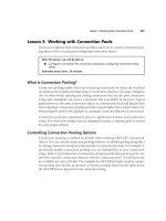
Protection: bus scrambling
In many smart card microcontrollers, the internal busses that drive the memory are scrambled.
This means that the individual bus lines are not laid out next to each other in increasing or
decreasing order, but are instead arranged randomly next to each other and ‘swapped’ several
times, or even arranged in several layers on top of each other. This represents an additional
hurdle for a potential attacker, who does not know which bus line is associated with which
address bit or function.
Scrambling the bus lines was originally introduced only in a static version, with the same
scrambling scheme used on every chip. With static scrambling, it would probably not be all
that difficult for an attacker to discover the scrambling scheme over a moderate length of time,
and thus be able to take it into account when tapping the busses.
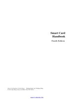
The security provided by this technique can be improved by using chip-specific scrambling.
This is naturally not achieved by using a different set of exposure masks for the busses of each
chip, since this is currently either not technically possible or affordable. Instead, scrambling
is performed by randomizer circuits located just ahead of the memory. These can be driven by
the chip serial number, for example. This technique is not difficult in terms of semiconductor
technology, and it makes life considerably more difficult for someone who tries to tap the bus.
Using variable input values for the randomizer makes it possible to achieve chip-specific and
session-specific scrambling.
CPU
data bus with
conventional chip layout
RAM
CPU
data bus with
chip-specific scrambling
data bus with
session-specific scrambling
RAM
data bus with
static scrambling
CPU RAM
CPU RAM
different for
each microcontroller
different for each session
or portion of a session
Figure 8.28 Bus scrambling in a smart card microcontroller, illustrated using an 8-bit data bus between
the CPU and the RAM. The data bus lines shown here represent information flows rather than electrical
leads. The encryption units are shown as separate components for the sake of clarity, but they are actually
intermingled with the rest of the components in such a manner that they cannot be recognized as separate
components, thus making them immune to attack
534 Security Techniques
Protection: irreversible switching from the test mode to the user mode
All microcontrollers have a test mode that is used for verifying the chips during the fabrication
process, and for executing internal test programs while the semiconductors are still in the
wafer or after they have been packaged in modules by the manufacturer. The test mode allows
types of access to the memory that are strictly forbidden when the chips are later in actual use.
However, for technical production reasons, it is an unavoidable requirement to be able to read
data from the EEPROM in this mode.
The change from the test mode to the user mode must be irreversible. This can be realized
by using a polysilicon fuse on the chip. In this case, a voltage is applied to a test point on the
chip that is provided for this purpose, and this voltage causes the fuse to melt through. The
chip is thus switched into the user mode using hardware. Normally, this cannot be reversed.
However, a fuse is by its nature a relatively large structure on the surface of the chip. It is
conceivable that the fuse could be mechanically bridged after the removing the part of the
passivation layer that covers the fuse. This would put the microcontroller back into the test
mode, and the memory could be read out using the extended access options available in this
mode. If the complete content of the memory is known, it is easy to clone the smart card that
has been read out.
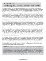
Figure 8.29 Photograph of a polysilicon fuse magnified 2000×. The picture on the left shows a fuse
that is still intact, while that on the right shows a blown fuse (Source: Giesecke & Devrient)
In order to defend against this type of attack, most semiconductor manufacturers have
adopted the practice of reserving a portion of the EEPROM for the switchover mechanism, in
addition to using a fuse. If a certain unalterable value is located in this part of the memory, the
chip has been irreversibly switched to the user mode. Even if the fuse is bridged over, the chip
will not return to the test mode, since the additional logical switch in the EEPROM prevents
this.
The security of the switchover from the test mode to the user mode can be increased even
further by a very simple measure. If the microcontroller chip is laid out on the wafer such
that the test pads needed to make contact with the chip for performing the tests are simply
sawn off when the wafer is divided into individual dice, neither a fuse nor any EEPROM cells
are needed to switch between the modes, since the elements needed for the test mode will no
8.2 Smart Card Security 535
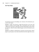
Figure 8.30 Photograph of a polysilicon fuse together with a microprobe needle, magnified 500×.
A blown fuse could be bridged using a microprobe needle (Source: Giesecke & Devrient)
longer be present. It is also be possible to replace the fuse that switches from the test mode
to the user mode by a track that is irreversibly broken when the dice are sawn from the wafer.
With present-day technology, it is not possible to make a connection to a sawn-through track
on the edge of a chip.
test pads
I/O
CLK
RST
Vcc
GND
RAM
CPU
NPU
EEPROM
ROM
cutting lines for
sawing the wafer
Figure 8.31 One of several possible ways to irreversibly remove the test pads used for testing the CPU
and memory of a smart card microcontroller
Dynamic analysis and defense: tapping the memory busses of the microcontroller
Before the busses between the CPU and the memories of the microcontroller (ROM, EEPROM
and RAM) can be tapped, the chip must be exposed and the passivation layer on the top surface
of the chip must be removed. The passivation layer protects the chip against oxidation, but it
also protects the chip against attack, since its integrity is monitored by sensors. According to
Anderson and Kuhn [Anderson 96b], it can be removed by etching with hydrofluoric acid. In
536 Security Techniques
addition, a laser cutter
10
can be used to selectively cut openings in the passivation layer at the
necessary locations.
After the passivation layer has been removed from the entire surface of the chip, or only
from selected locations, it would be at least theoretically possible to make contact with the
address, data and control busses for the memory using microprobe needles. If it is possible to
make electrical connections to all the lines of these three busses, it is very easy to address the
individual memory cells and to read any desired regions of the ROM and EEPROM. The chip
does not have to be powered for this, and any desired type of connection jig can be used. The
consequences of a successful attack using this method would be serious, since in principle it
would make all the secret data in the non-volatile memory readable.
This method could be extended by making connections to the busses and then operating the
chip in the normal manner. In this way, it would be possible to eavesdrop on the complete data
traffic between the CPU and the memories, and this could be recorded using a sufficiently fast
logic analyzer.
As already indicated, it is very difficult to make electrical contact with the individual tracks
on the chip. With an 8-bit microcontroller, the number of connections needed for this attack
is 16 for the address bus, 8 for the data bus and 1 to 4 for the control bus. In total, at least
25 simultaneous connections would have to be created between an external analysis computer
and the tracks on the chip. Even with modern micromanipulator technology, this is currently
not possible, due to the very small dimensions of the semiconductor structures. However, it
would be possible to use a focused ion beam (FIB) generator, which is commonly used in the
semiconductor industry, to implant a sort of electrically conductive contact surface for each
bus line. These surfaces then could be used as contact points for microprobe needles. However,
the effort required for this is enormous.
Even if an attacker succeeded in making these connections, he would still have to determine
how the busses have been scrambled before he could successfully read the data. This is because
the individual bus tracks are not arranged on the chip in an orderly fashion next to each other,
but are instead arranged in an externally unrecognizable manner.
If markedly improved technology in the future should make it possible to make connec-
tions to the busses of current microcontrollers, that would probably not have any effect on
security, since by that time semiconductor structures will have become significantly finer than
they presently are. In addition, micromechanical technology will probably always lag behind
semiconductor technology, which is based on optical processes. This means that even in the
future, this sort of attack will probably not be suitable for significantly weakening the security
of smart cards.
Dynamic analysis and defense: measuring the current consumption of the CPU
Already in 1995, in the first edition of this book, the following statement appeared at this point:
‘The design of the processor is also crucial with regard to security. A smart card processor must
have nearly the same current consumption for all machine instructions. Otherwise, conclusions
can be drawn regarding the instruction being processed, based on the current consumption. A
certain amount of secret information can be deduced from these conclusions.’ The fact that it
10
A laser cutter is a device for drilling and cutting using a high-power laser beam. It has an precision of a fraction of
a micron
8.2 Smart Card Security 537
Figure 8.32 An example of using a focused ion beam (FIB) on a semiconductor chip. The track on the
surface of the chip running from the top to the bottom of the picture has been separated using an FIB and
then connected to a parallel track using a newly deposited metalization structure, which can be seen in
the upper part of the picture. This structure was also created using the FIB (Source: Fraunhofer Institute
for Integrated Circuits, Component Technology Group)
is possible to draw conclusions about the instructions being executed by a processor, and even
about the data being processed, by analyzing the current consumption of the processor while it
is executing instructions, was thus already known for several years when Paul Kocher, Joshua
Jaffe and Benjamin Jun published a paper on simple power analysis (SPA) and differential
power analysis (DPA) in June of 1998 [Kocher 98].
11
The working principle of simple power analysis is relatively straightforward. The current
consumption of the microcontroller is determined by measuring the voltage drop across a
resistor connected in series with the power supply. Measurements are made at high time res-
olution using an analog-to-digital converter. With a high-performance processor, such as a
Pentium or PowerPC, it would not be possible to draw any conclusions about the instruc-
tions being executed, due to the complexity of the internal processes. However, the relatively
simple structures of the 8051 and 6085 CPUs used in smart card microcontrollers result in
11
A detailed summary of this subject can be found in [Kocher 98b] and [Messerges 99]
538 Security Techniques
measurable and thus interpretable variations in current consumption, according to the instruc-
tions and data being processed. To help clarify the principle, imagine that a particular program
sequence with a particular set of data always produces the same plot of processor current
versus time. If the same program is then run using different data, the plot of current versus time
will be different. This variation is used to determine which data have been processed by the
program.
+ 5 V
GND
reset
clock
data transfer
resistor R
to voltmeter
Vcc
RST
CLK
GND
RFU
I/O
Figure 8.33 Circuit diagram of the connections to a smart card microcontroller needed to make simple
current measurements using a series resistor
Differential power analysis (DPA) can reveal even finer differences in the current consump-
tion of a microcontroller than simple power analysis. With the DPA technique, the current
consumption is first measured while the microcontroller is processing known data, and then
again while it is processing unknown data. The measurements are repeated many times, so that
the effects of noise can be eliminated by taking average values. The differences are calculated
once the measurements have been completed, and conclusions regarding the unknown data are
drawn from the results.
In the paper by Kocher et al., ‘high-order differential power analysis’ (HO-DPA) is men-
tioned as a further extension of DPA. This involves measuring not only the current consumption
of the microcontroller, but also other variables that depend on the program being executed by
the processor, such as the electromagnetic radiation of the chip. The measurement information
collected in this manner using both known and unknown data can be used in the same way as
in the DPA technique to calculate differences, which can then be used to compute the unknown
data.
These three types of power analysis for smart card microcontrollers represent very se-
rious forms of attack on hardware and software that have not been protected by suitable
countermeasures. This is because the current consumption of some microcontrollers is defi-
nitely dependent on the machine instructions being executed and the data being processed by
the instruction. In addition, the cost and complexity of the equipment needed for a successful
attack using this method is relatively limited. However, there are several effective countermea-
sures based on suitably improved hardware and modified software.
8.2 Smart Card Security 539
NOP (no operation)
machine instruction
MUL (multiply)
machine instruction
JMP (jump)
machine instruction
time
current
consumption
Figure 8.34 Simplified representation of variations in the current consumption of a smart card micro-
controller while it is processing several different machine instructions. Besides being dependent on the
machine instruction being processed, the current consumption of the processor may also depend on the
data being processed
The simplest hardware solution is to incorporate a fast-acting voltage regulator in the chip
that uses a sense resistor to monitor the current drawn by the microcontroller and ensures
that it is independent of the instructions and data. Artificial noise current generators on the
chip are also an effective solution. A technically more complicated solution is to use a modi-
fied processor design that always draws a constant current. However, all of these approaches
slightly increase the power consumption of the microcontroller, which is undesirable in certain
application areas, such as telecommunications. An alternative, simpler defense measure can be
to activate certain components of the microcontroller that are not needed for the actual process
while performing SPA/DPA-critical processes. The CRC checksum generator or numerical
coprocessor could be used for this purpose, using random data as input values in order to
generate artificial noise in the current consumption.
Using randomly generated delays (random wait states) in the processor considerably in-
creases the difficulty of synchronizing the data obtained from current analysis, without in-
creasing the chip’s current consumption. A similar approach can be used with smart card
microcontrollers that have their own on-chip clock generators, by continuously and randomly
varying the clock frequency within certain limits.
There is presently an immense range of possible software countermeasures. Here we can de-
scribe a few representative examples. The simplest approach is to use only machine instructions
that have very similar current consumptions. In this case, machine instructions whose current
consumption is significantly different from the average level are not allowed to be used in the
assembler code. Another approach is to have several different, randomly selected procedures
for performing the same computations in cryptographic algorithms. This makes it consider-
ably more difficult for the observer to recognize a correlation between known and unknown
machine instructions or processed data. In order to make it more difficult to obtain the data
needed to successfully perform a power analysis, all keys should be protected by irreversible
540 Security Techniques
command to
the smart card
microcontroller awakens
from the sleep state
microcontroller re-enters
the sleep state
command processing
in the smart card
response frlom
the smart card
time
time
I/O lead
Figure 8.35 Simplified representation of the current consumption of a smart card microcontroller in
the quiescent state and variations in its current consumption during operation. From the current drawn
by the microcontroller, it is possible to recognize when it is awakened from the sleep state by the first
falling edge on the I/O line, following which it exhibits a continuously varying current consumption that
depends on the machine instructions being executed
retry counters. In addition, it is necessary to block free access to all commands (such as
INTERNAL AUTHENTICATE) that can be used to pass any desired data through a crypto-
graphic algorithm in the smart card. If it is essential to use commands of this sort for some
reason, the smart card must test the authenticity of the terminal before executing them. Re-
stricting the use of the available commands also makes it more difficult to collect reference
data for a subsequent power analysis.
As a matter of principle, secret data should never be processed bitwise, since doing so
considerably simplifies SPA/DPA analysis. When keys have to be loaded into the registers
of a cryptoprocessor, in some implementations they are intermixed with random numbers
that are also loaded in these registers as dummy values, in order to render the corresponding
measurements meaningless. Of course, the true keys must be located in the registers at the end
of the loading process.
8.2 Smart Card Security 541
SPA/DPA techniques are not just limited to ferreting out secret data stored in smart cards.
They can also be used for purposes such as convincingly demonstrating that specific program
code is used in a smart card. This is done by making an SPA analysis of the function in question
in the smart card and comparing the current consumption plot obtained in this manner with the
plot for a reference card. Even if the source code is not known, under favorable conditions this
technique can for example be used to prove that segments of program code from an outside
source are being used in a competitor’s product. The technical basis for this is the fact that
generally speaking, the machine code produced from the same source code by a given compiler
will also be the same. The differences arising from the subsequent linking process, due to the
almost certain differences in code localization in the memory, are relatively small.
Testing software in smart cards for resistance to SPA/DPA attacks has presently reached
a high level of refinement and thus taken on the character of a specialist discipline. It has
become common for measurements to be made periodically during software development,
with the software being modified as necessary according to the results of the measurements
in order to defeat SPA/DPA attacks. At the early stages of development, measurements are
made with the software in EEPROM, and the analyses are repeated and refined when the first
samples are obtained from the semiconductor manufacturer with the software in the ROM of the
microcontroller. This is because experience has shown that this aspect is definitely significant
with regard to SPA/DPA measurements.
By their nature, SPA and DPA can be used for more than just mounting attacks on cryp-
tographic algorithms. Both methods are also very suitable for analyzing all activities of the
processor. With suitable experience and equipment, it is even possible to determine the data
involved in copy operations within the memory of a smart card that is not resistant to these
types of attack.
Analysis and defense: measuring the electromagnetic radiation of the CPU
It is at least theoretically possible to draw conclusions about the internal processes of the smart
card microcontroller from measurements of its electromagnetic radiation, in the same manner
as with differential power analysis. Magnetic fields with small dimensions and strengths can
be measured using SQUIDs (superconducting quantum interference devices). However, this is
technically enormously difficult, and the knowledge of the internal structure of the semicon-
ductor device that is indispensable for this method is not generally available. In addition, ICs
can be very effectively protected against this sort of attack by stacking several traces on top
of each other, so that even if a magnetic field can be measured, it is not possible to determine
which of the tracks is actually carrying the associated current.
Manipulating the smart card microcontroller
Manipulation and defense: altering the memory content of the smart card microcontroller
Directly reading the memory content of a microcontroller is a possible attack scenario whose
danger can be appreciated at first glance. A similar scenario that is almost as strong a form of
attack is intentionally altering the data content in a memory of the smart card microcontroller.
This does not mean randomly introducing errors in the computation process of a cryptographic
542 Security Techniques
algorithm, which forms the basis of differential fault analysis (DFA), but instead selectively
changing the values of certain bits or bytes in the ROM or EEPROM.
Non-selective changes in all types of memory can be produced by (for example) exposing
the module to X-rays or shining ultraviolet light on the exposed chip. EEPROM cells can be
discharged by exposing them to ultraviolet light, which causes their contents to take on the
value of the lowest-energy state. This process is exactly the same as erasing a conventional
EPROM using an ultraviolet lamp. However, it cannot reasonably be used for an attack, since
the attacker has no control over which EEPROM cells are switched.
However, the ultraviolet lamp can be replaced by a collimated beam of light or light from a
laser, and this can be focused to a fine point. This could certainly be used to alter the contents
of individual memory cells. The advantage of using a laser is that it can supply enough power
to also modify the contents of ROM cells. A focused ion beam can also be used in a similar
manner to change the contents of memory cells.
The changes that are possible can certainly be used for theoretically effective attacks. For
example, the random number generator could be manipulated such that it no longer produced
random numbers, but instead always supplied the same value. If this were possible, authenti-
cation of the terminal by the smart card could be broken by a replay attack using a previously
employed value.
It is certainly possible to imagine other types of attacks that could be carried out if the
contents of specific memory bits could be intentionally modified. For example, all S boxes
of the DES algorithm could be intentionally changed to a uniform value of zero or one. This
would mean that the DES algorithm would no longer act as an encryption algorithm, but only
as a linear transformation [Anderson 96a].
If the exact location of the DES key in the EEPROM is known and it is also possible to
modify individual bits in the EEPROM (using focused ultraviolet light, for example), it is
naturally possible to utilize these conditions to mount an effective attack. This attack consists
of setting an arbitrary bit of the key to 0 and then calling a command that uses the DES
algorithm with the modified key. If the return code indicates a parity error in the key, the bit
that has been modified was originally set to 1, while if no parity error is reported, the bit was
already set to 0. The same procedure is then followed for the remaining 55 bits of the key, with
the result that the secret key is known [Zieschang 98].
Many other types of attack along the same lines are possible, such as selectively modifying
program processes or altering pointer values. These attacks may look very simple and attractive
on paper, but it would be very difficult to carry them out in actual practice. The necessary
conditions for a successful attack are not exactly easy to achieve, so this type of attack remains
an interesting but theoretical concept.
In order to alter bits selectively, an attacker must have detailed knowledge of the physical
addresses of the data and program code in the memory, and he must also know the scrambling
and/or encryption schemes used for the memory in question. In addition, all data and routines
that are significant with regard to security are protected using checksums that are always
checked before using the data or routine. This means that the attacker would also have to
selectively modify the checksum to match the modified data. You should also not overlook
the fact that all protective layers covering the memory in question must be neutralized before
any manipulation can take place. All of these considerations together reduce the attractiveness
of this type of attack to almost nothing, even though it must be admitted that it sounds very
attractive in theory.
8.2 Smart Card Security 543
Attacks at the logical level
The main prerequisite for attacks on the security of a smart card at the logical level is
knowledge of the communications and information flow between the terminal and the smart
card. In this case it is not particularly necessary to understand the processes occurring at the
hardware level, but rather the software processes. In terms of information technology, the
sample scenarios described here are located one level above attacks that primarily exploit the
properties of the hardware.
Attack and defense: dummy smart cards
Probably the simplest imaginable type of attack is to use a smart card that has been custom
programmed and includes additional logging and analysis functions. Up until a few years ago,
this was practically unfeasible, since only a few companies had access to smart cards and
the microcontrollers used to produce them. Nowadays, though, smart cards and configuration
programs can be freely purchased from a number of companies. This naturally increases
the options available to an attacker. Even without this, with a certain amount of effort and
dexterity it is possible to assemble a working smart card using a plastic card and a standard
microcontroller in an SMD package. Such a card can at least be made to imitate the electrical
Figure 8.36 Rear view of an opened smart card module. The chip at the left is a standard PIC microcon-
troller that is connected to an EEPROM memory chip at the right by bonding wires and tracks. This type
of chip module is typically used for cloned smart cards and other types of attacks on smart card systems
544 Security Techniques
Vcc
PIC 16F84
11
18 8
24LC
16B
RST
CLK
RFU
GND
Vpp
I/O
RFU
Figure 8.37 A typical substitute circuit for an smart card microcontroller built using standard discrete
components (PIC 16F84 microcontroller and 24LC16B EEPROM memory chip). These components fit
into a typical smart card module, so it is not possible to detect any difference from a genuine smart card
microcontroller without investigating the module. This circuit and variations on it can be found on the
relevant Internet sites
interface of a real smart card and to behave the same way for data transfers. It is now possible
to obtain such cards from a wide variety of sources via the Internet. New possibilities are also
offered by Java technology for smart cards, which makes it easy to generate programs and load
them into dummy cards.
With such a dummy card, it would be possible to record at least a part of the communications
with a terminal and subsequently evaluate this information. After several attempts, it would
probably be possible to perform part of the communications in exactly the same way as a
genuine smart card. Whether this can be put to advantage is doubtful, since all professionally
designed applications have cryptographic protection for important activities. As long as the
secret key is not known, the attack will not go any farther than the first authentication. Such
an attack can only be successful if the secret key is known or the complete application runs
without any cryptographic protection. Should such an application exist, it is highly doubtful
that any benefits that could be obtained from this type of attack would be sufficiently large to
justify the necessary effort.
Analysis: determining the command set of a smart card
The instruction classes and commands that are supported by a smart card are of course not
often published, but it is very easy to determine what they are. This is more interesting with
regard to completely determining the command set of a smart card than it is for an attack on
the security of the smart card. However, it is conceivable that an attack could be mounted on
the basis of this information.
The method used to determine the command repertoire is illustrated in Figure 8.38. The first
step is to generate a command APDU and send it to the smart card using a freely programmable
terminal. The class byte in the APDU is changed for each APDU to cover the range from
'00' to'FF'. As soon as a return code other than ‘invalid class’ is received, the first valid class
byte has been determined. There are usually two or three valid instruction classes, which can
then be used to try all possible instruction bytes in the next round. This consists of sending
command APDUs with various instruction bytes to the smart card and noting the ones that
yield a return code other than ‘unknown instruction’. If suitable software is available in the
terminal, this method can be used determine which commands are supported by a particular
8.2 Smart Card Security 545
smart card in one to two minutes. To a certain extent, a portion of the possible parameters of
the commands so identified can also be determined in a similar manner.
This algorithm can be made considerably faster by using only the class byte codes allowed
by the ISO/IEC 7816-4 standard and allowing the instruction byte to be an indexed variable.
This strongly reduces the number space of the class byte by taking secure messaging and
logical channels into account. A similar improvement can be made by using only even-valued
instruction bytes, since the odd-valued codes contain only the V
pp
control information, which
is no longer used.
start
P1 := '00'
P2 := '00'
command APDU :=
CLA || INS || P1 || P2
arbitrary values
may be assigned
to P1 and P2
send
command APDU
receive
response APDU
class supported by
smart card found
(= CLA)
SW1 || SW2 =
'6E00' ?
CLA := CLA + 1
command APDU :=
CLA || INS || P1 || P2
CLA = 256 ?
1
1
INS := 0
send
command APDU
receive
response APDU
SW1 || SW2 =
'6D00' ?
INS := INS + 1
INS = 256 ?
CLA := '00'
end
command
supported by
smart card found
(= INS)
no
yes
2
2
no
yes
no
yes
yes
no
'6D00' represents
a non-supported
command
'6E00' represents
a non-supported
class
Figure 8.38 Basic procedure for performing an exhaustive search for all commands supported by a
smart card operating system. The results of the search will only be complete if command invocation is
not controlled by a state machine. The procedure works on the principle of systematically testing all class
byte (CLS) and instruction byte (INS) codes in turn, ignoring any command contents that may be present
(secure messaging, logical channels, V
pp
control and so on)
The reason that this simple search algorithm for instruction classes, commands and param-
eters can be so effective is that practically all command interpreters in smart card operating
systems evaluate received commands by starting with the class byte and working through the
following bytes. This process is terminated as soon as the first invalid byte is recognized, and
546 Security Techniques
a suitable return code is generated and sent back to the terminal. However, it can only work
if the smart card does not have a global state machine that monitors the command sequence.
If such a state machine is present, it is at least possible to use this procedure to determine the
command sequence in a step-by-step manner.
The utility of such a procedure for an attacker may not appear to be that great, since the
command set is usually not secret. However, it does at least provide a simple and fast means
to determine all of the available commands. It is also a very useful means for determining
whether the producer of the operating system has incorporated any undocumented commands
in the software.
Attack: tapping data transmissions
A slightly modified smart card can be used to tap data transmissions during a session and
manipulate the data as desired. The modifications consist of gluing an insulated dummy contact
on top of the I/O contact, so that the original I/O interface is no longer connected to the I/O
contact. The new (dummy) contact and the original I/O contact are then connected to a fast
computer. With suitable programming, this computer can delete or insert any desired data within
the communications between the terminal and the smart card. If the computer is sufficiently fast,
neither the terminal nor the card will detect any difference between normal and manipulated
communications.
Figure 8.39 An adapter that can be used to extend a smart card outside of a terminal enclosure in
order to allow measurements to be made on the card. The eight contacts can be seen on the left, and a
prototyping area for electronic circuitry can be seen on the right
It is clear that the course of a session can be radically affected using this method. Whether
an attacker can derive any benefit from this method depends primarily on the application in
the smart card. A well-known design principle says that eavesdropping on communications or
the deletion or insertion of data in the communications stream must not be allowed to impair
security. If this principle is not observed, an attacker can certainly obtain an advantage using
this method. There are known cases of fraud using simulated memory cards.
In order to provide protection against this type of attack, some terminals have shutters
that cut off any wires attached to the smart card. Secure messaging can also be used very
effectively here to allow any manipulation of the data during the data transmission to be
reliably detected.
8.2 Smart Card Security 547
Many terminals may be used only under supervision, which makes it difficult to use manip-
ulated cards with leads to an accompanying computer in such terminals. In summary, although
this type of attack can be regarded as very interesting and quite promising in theory, in practice
it achieves only modest success.
Attack and defense: power interruption
A type of attack that was successful with many smart cards until recently is to interrupt the
power to the card at a particular time while a command is being executed. This type of attack is
based on the fact that with conventional programming, all write operations to EEPROM pages
are performed sequentially. If the programmer has not been clever in arranging the order of the
write operations, an attacker can derive an advantage by cutting off power at the right time.
This can be briefly illustrated using a highly simplified example. In an electronic purse
application, if the balance is increased before the log file is updated when processing a purse
loading command, an attacker would have a good chance of being able to load a smart card
for free. He would only have to switch off the power at the right time, or jerk the card out of
the terminal with millisecond accuracy (!). The purse balance would then have been changed
to the new value, but there would no log record for this transaction and no response to the
command. With simple electronic purse systems in the past, such an attack was certainly a real
possibility.
In order to determine the exact time to terminate processing, the attacker only has to use
an electronic counter to count the number of clock pulses after the time when the command is
sent and then perform a series of experiments with increasing clock counts to determine the
proper time to interrupt power to the card. It hardly needs to be said that the entire procedure
can be more or less automated using a computer.
purse balance file
(in binary notation)
purse
balance
1. current purse balance
2. deduct 10 EUR
3. erase the EEPROM
4. write the new purse balance
100 EUR
90
255
90
EUR
EUR
EUR
°0110 0100°
°1111 1111°
°0101 1010°
Figure 8.40 Example procedure for writing a new balance in an electronic purse. Here it is assumed
that the erased state of the EEPROM represents a logic 1. Due to the way the EEPROM works, this
means that the entire EEPROM page must be erased (which means setting all of its bits to 1) if only one
bit in the page must be changed from 0 to 1. In this example, if the power for the smart card is cut off
exactly after the EEPROM has been erased, which means after step 3, the purse balance would be set to
its maximum value and the attacker would have effectively created money. This can be reliably prevented
by using atomic operations
Although this type of attack sounds attractive and appears to be easy to copy, in practice there
are several effective countermeasures. The simplest approach is arrange the EEPROM write
548 Security Techniques
instructions in a carefully considered order. The EN 1546 standard for multisector electronic
purses is well worth examining in this regard, since all of the electronic purses described in
this standard are explicitly protected against this sort of attack.
However, even a perfectly ordered sequence of write operations cannot by itself achieve
absolute protection. This can be illustrated using another example. When the electronic purse
of our previous example is being loaded, it may be necessary to erase the EEPROM before
the write process. If the erased state of the EEPROM corresponds to the maximum value of
the purse balance, which incidentally is the usual case, the purse can be artificially loaded to
its maximum value by simply interrupting the power to the card at the right time. The proper
moment is when the erase operation has just been completed and the write operation has not
yet been started.
Operating system designers know an effective countermeasure for this type of attack, which
is to use atomic operations as described in detail in Section 5.10. The characteristic of an atomic
operation is that it is indivisible, which means that it is performed either completely or not
at all. This provides fully adequate protection against the type of attack just described. Even
the optimally ordered EEPROM write operations described in the EN 1546 standard require
atomic operations in several locations to prevent this type of attack from being implemented.
Attack and defense: current analysis during PIN comparison
A technically very interesting type of attack on comparison features, such as PINs, can be
carried out using a combination of physical measurement of a parameter and variation of
logical values. This type of attack relates to all mechanisms in which data are sent to the
smart card and compared in the card with corresponding values, with a retry counter being
incremented according to the result of the comparison.
The attack works on the principle of measuring the current drawn by the card, for example by
measuring the voltage drop across a resistor in the Vcc lead. If a suitable command containing
the comparison data is sent to the card, it is possible to see from the current measurement
whether the retry counter has been incremented, even before the return code has been received.
If the return code is sent before the retry counter is written when the result of the comparison is
positive, this method can be used to determine the value of the reference data. This is done by
sending all possible variations of the comparison value to the smart card and cutting off power
to the card before the retry counter has been incremented if the result is negative. A positive
result can be clearly recognized from the associated return code, which is sent before the retry
counter is written.
There are two basic ways to defend against this type of attack. The simplest defense consists
of always incrementing the retry counter before making the comparison, and then decrementing
it afterwards as appropriate. In this case, the attacker cannot obtain an advantage, regardless of
when he interrupts power to the card, since the retry counter will have already been incremented.
The second defense is more complicated, but it provides similar protection. In this approach,
the retry counter is incremented after a negative comparison and written to an unused EEPROM
cell after a positive comparison. Both of these write accesses occur at the same time in the
process, so the attacker can draw no conclusions with regard to the result of the comparison.
He learns the result of the comparison only after receiving the return code, and at this point it
is too late to prevent a write access to the retry counter by cutting off the power.
8.2 Smart Card Security 549
Attack and defense: timing analysis of PIN comparisons
Programmers always give considerable attention to making programs execute as quickly as
possible. Normally, this is also an important consideration. However, the fact that the execution
time of a process has been optimized can be utilized for an attack that definitely has a good
chance of success. If a PIN is sent to a smart card for comparison, the associated comparison
routine normally compares the PIN it receives with the stored PIN value byte by byte. A pro-
grammer who is not security-conscious will program this routine such that the first difference
between the two compared values causes the routine to immediately terminate and return to
the calling program. This leads to minute variations in the execution time of the comparison
process, which can nevertheless be measured using suitable equipment (such as a storage os-
cilloscope). This information could be used by an attacker to determine the secret PIN code in
a relatively straightforward manner.
Up to a few years ago, this was still an effective type of attack on smart cards. However, it
is now a known type of attack, and comparison routines are constructed such that all digits of
a PIN are always compared. Consequently, there is no time difference between positive and
negative comparison results.
Protection: noise-free cryptographic algorithms
The security of smart card applications is based on secret keys used with cryptographic algo-
rithms. In order to access the card in certain ways or perform certain operations with the card,
the terminal must always first authenticate itself using a secret key. Naturally, authentication
of the terminal by the card represents an attractive target for an attacker. By contrast, authen-
tication of the card by the terminal is not attractive with respect to an attack on the card, since
a smart card can be manipulated as desired using a (dummy) terminal.
The smart card authenticates the terminal by sending it a random number, which the terminal
then encrypts and returns to the card. The smart card then performs the same encryption and
compares the result with the value received from the terminal. If the two values match, the ter-
minal has been authenticated, and it receives a corresponding return code. If the authentication
fails, the card sends a different return code. The starting point for the attacker is analyzing the
processing time between when the command is sent and when the response is returned by the
smart card.
As late as the early 1990s, cryptographic algorithms with significant differences in execution
times for different keys and plaintexts were still sometimes used. The resulting reduction of the
key space can be exploited by an attacker to search for the secret key using a brute-force attack.
The duration of the search is strongly dependent on the noise level of the algorithm. The size of
the key space becomes smaller as the variation in execution time increases, making it easier and
faster to search for the key. If the exact implementation of the algorithm on the target computer
is known, this information can also be included as reference data for generating the timing
tables. This type of attack was made public under the name ‘timing attack’ in a publication
by Paul Kocher in 1995 [Kocher 95], which primarily deals with the time dependencies of the
RSA and DSS algorithms.
In principle, a timing analysis is a very dangerous threat to the security of a smart card.
However, since this type of attack has been known for a relatively long time, all present-day
smart cards use only noise-free cryptographic algorithms, which are algorithms for which the
550 Security Techniques
time required for encryption or decryption is independent of the input values. This blocks
this sort of attack. However, the programmer has conflicting interests in this regard, since a
noise-free algorithm usually requires more program code and is always slower than a noisy
version. The reason for this is that a noise-free algorithm must be designed such that the path
through the program has the same length for all combinations of plaintext data, ciphertext data
and keys. This means that the longest necessary path is the reference value, and all other paths
must be suitably modified to match this length.
To provide additional security, in some applications all authentication keys have their own
retry counters, so that only a limited number of unsuccessful authentications can be performed.
Once the retry counter has reached its maximum value, the smart card blocks all further attempts
at authentication.
key
computation
time
plaintext
11 ms
12 ms
13 ms
14 ms
15 ms
16 ms
Figure 8.41 Example of the effects of ciphertext and plaintext data on a noisy encryption algorithm.
This plot shows a portion of the plaintext / ciphertext space. It was generated using an old implementation
of the DES algorithm, with 100,000 iterations per measurement value
Manipulation: differential fault analysis (DFA)
As is well known, the operation of electronic devices can be adversely affected by exposing
them to electromagnetic interference. For instance, a mobile telephone can cause the processors
of many types of small computer-controlled appliances to crash. The cause lies in the memory
cells, whose contents can be altered by the high-frequency AC fields.
In 1996, Dan Boneh, Richard DeMillo and Richard Lipton published a study [Boneh 96]
describing a theoretical method for determining the secret keys of asymmetric cryptographic
algorithms by introducing scattered hardware errors. Since the three discoverers of this method
worked at the Bell Communications Research (Bellcore) Laboratories at the time, this type of
attack is often called the Bellcore attack.
Only two months later, Eli Biham and Adi Shamir published an extension of the Bellcore
attack called differential fault analysis (DFA) [Biham 96], which also included symmetric
8.2 Smart Card Security 551
cryptographic algorithms such as DES. This meant that, at least in theory, many smart card
applications were exposed to a new and serious form of attack.
The basic principle of both of these types of attack is relatively simple. In the first step, an
arbitrary plaintext is encrypted using the key to be broken, and the resulting ciphertext is saved.
Following this, the operation of the card is disturbed while it is processing the cryptographic
algorithm, for example by exposing it to ionizing radiation or high-frequency fields in order
to alter a single bit of the key in a random location while the computation is being performed.
This yields a ciphertext that is incorrectly encrypted, due to the altered bit. This process is
repeated many times, and all the results are saved for analysis. The remainder of the procedure
for determining the value of the secret key is purely mathematical, and it is fully described in
the papers just mentioned.
The strength of this attack is primarily due to the fact that it is not even necessary to know
the location of the altered bit in the secret key. Biham and Shamir state in their publication that
with a single corrupted key bit, 200 ciphertext blocks are sufficient to compute the value of the
secret DES key. If triple DES (with a 168-bit key) is used in place of simple DES, the number
of required ciphertexts does not increase significantly. Even if more than one bit is altered, this
attack remains effective; the only consequence is that more incorrectly encrypted ciphertexts
are needed.
In practice, this type of attack is not as simple as it sounds. If at all possible, only one bit
should be altered, or at least only very few bits. If the entire microcontroller is simply bathed
in microwave radiation, usually so many bits will be altered that the processor will hopelessly
crash. Consequently, an attempt is made to induce the processor to make isolated processing
errors by injecting specially prepared glitches
12
into the power or clock lines. If the filter on the
associated input leads cannot neutralize these glitches, they can produce the desired processing
errors.
However, a smart card is not totally helpless in the face of a Bellcore attack or DFA if
suitable precautions are taken. The simplest defense is to simply compute the cryptographic
algorithm twice and compare the two results. If they match, no attempt has been made to alter
any bits from outside the card. This defense assumes that intentionally introduced random
errors can never alter the same bit twice in a row. This is a realistic assumption, since if it ever
became possible to selectively alter specific bits in a smart card processor, attacks that are much
simpler and faster than DFA would be possible. The main disadvantage of double computation
is the additional time that it requires, which can cause problems. This applies primarily to
attacks on time-intensive asymmetric cryptographic procedures, such as RSA and DSS.
Another effective defensive measure against differential fault analysis can be achieved by
always encrypting different plaintexts. The simplest solution is to prefix the plaintext to be
encrypted with a random number. This means that the cryptographic algorithm always encrypts
different data, which prevents DFA from being used.
In summary, the Bellcore attack and differential fault analysis are unquestionably dangerous
types of attack that can succeed with smart cards that do not incorporate adequate protective
measures. However, all smart card operating systems and applications were modified to protect
them against these types of attack shortly after they became known, so neither the Bellcore
attack nor DFA currently represents a serious threat.
12
A glitch is a very brief interruption or spike in the voltage or current
552 Security Techniques
Attack and defense: disturbing the processor
A type of attack that is similar to using differential fault analysis to attack the secret key
of a cryptographic algorithm consists of attempting to affect the execution of program code
routines by disturbing the operation of the processor. A type of attack that has been known
to manufacturers of smart cards and smart card microcontrollers since around 1998 is the
‘light attack’, which was described in mid-2002 by Sergei Skorobogatov and Ross Anderson
[Skorobogatov 02] as an ‘optical fault induction attack’.
This paper describes an arrangement in which a standard commercial flash unit is attached
to the camera adapter flange of a conventional optical microscope. Following this, a highly
restricted region of the RAM of a standard microcontroller (PIC16F84) is exposed to light
from the flash unit. With microcontrollers that are not hardened to resist this type of attack, this
arrangement can be used to selectively set certain bits in the RAM to the logic 0 or 1 states.
The operation of the processor can be disturbed by applying glitches to the supply lines,
exposing the chip to flashes of light or using high-frequency radiation [Lamla 00], among other
things. If the disturbance is triggered at the proper instant during the execution of the program,
it can be used to intentionally influence a query operation, for instance. A simple example
of this is shown in Figure 8.42. The task of the illustrated routine is to send the content of a
transmit buffer, whose boundaries are specified by a start address and an end address. If the
attacker succeeds in intentionally disturbing the query that determines the end address of the
transmit buffer, data following the end of the transmit buffer will also be sent to the terminal.
Should the workspace for a cryptographic algorithm be located in this region of memory, its
keys could be illicitly read out in this manner.
send content
of transmit buffer
send byte at
pointer address
pointer :=
start address
pointer =
end address?
yesno
pointer :=
pointer + 1
end
transmit buffer
in RAM
start address
pointer
end address
program flow for
data transmission
Figure 8.42 Example of a non-robust routine for sending the content of a transmit buffer, which can
be successfully attacked by disturbing the processor
The defense against this attack involves several system levels. At the hardware level, it is
important for the smart card microcontroller to have suitable sensors, so that it can detect all
8.2 Smart Card Security 553
attempts to disturb the processor. These sensors can include voltage glitch detectors and a large
number of suitable light sensors. In order to make it impossible to defeat a few light sensors
by covering them with black ink, it is a good idea to use a relatively large number of sensors
distributed over the surface of the chip. This by itself is sufficient to preclude many types of
attack. An opaque chip encapsulation material provides only limited protection, since it can
be removed relatively easily using chemical methods.
The second level of protection must be implemented in the software. The program code
shown in the example can be made significantly more robust by using an ‘equal to’ query
instead of a ‘less than or equal to’ query. Another countermeasure is to execute the query
twice, with a random delay between the two queries. This requires the attacker to use two
flashes of light to manipulate the query, and he will be additionally hindered by the fact that
he cannot exactly predict the timing of the second flash.
In addition, all confidential data stored in RAM should be immediately deleted after they
have been used, or they should be temporarily encrypted. In order to further reduce the con-
sequences of this type of attack, it is also a good idea to encrypt all secret data (such as PIN
codes and keys) located in EEPROM. Should an attacker succeed in reading out portions of the
EEPROM by manipulating queries, he would then only obtain encrypted data, which would
be of no use to him. If an MMU is present, it can also be configured to monitor compliance
with certain boundaries for transmitting data from the card. Furthermore, modern processors
can detect illegal machine instructions and invalid addresses and respond appropriately. As can
be clearly seen from this defense scenario, an attack that unquestionably can be regarded as
serious can be blocked by suitable combination protective measures in hardware and software.
Protective elements: smart card operating systems
Protective mechanisms in the hardware form the basis for protective mechanisms in the oper-
ating system software. No potential weakness may be overlooked, since the three components
of the protective mechanisms – hardware, operating system and application – are linked in a
logical AND relationship. This is similar to a chain, in which the weakest link determines its
breaking strength. If a particular mechanism fails in a smart card, the entire security of the
card collapses. The operating system in particular forms the basis for the actual application,
whose information and processes must be protected.
The following material deals specifically with measures for protecting against typical at-
tacks, rather than general smart card security functions. However, most of these general func-
tions also contribute significantly to operational security and protection against attacks. For
this reason, you are explicitly referred to the appropriate sections of Chapter 5.
Protection: hardware and software tests following a reset
When the operating system is initialized, at minimum the most important parts of the hard-
ware must be tested to see if they are in proper working order. For instance, a RAM test is
indispensable, since all access conditions are stored in the RAM while the chip is operating,
and failure of a single bit could cause a complete security collapse. It is likewise necessary to
compute and test the checksums for the most important portions of the ROM and EEPROM.
The CPU is at least implicitly tested by sending the ATR, since the bulk of all possible machine
554 Security Techniques
instructions must be executed faultlessly for this to be possible. Explicit testing of the CPU
and any NPU that may be present can usually be limited to sample testing, since completely
testing all functions for flawless operation would take too much time and code.
If the operating system discovers a hardware error or checksum error, there are two possible
ways to proceed. The first option is for the software to immediately jump to an endless loop,
which means that an ATR cannot be sent and subsequent commands can no longer be received.
The main disadvantage of this is that the cause of this behavior cannot be recognized from the
outside. The problem might be a broken bonding wire, a fractured chip or a checksum error in
the EEPROM, but this cannot be determined by the user. A better option is to have the smart
card attempt to send a special ATR before disabling itself by entering an endless loop. The
error ATR at least gives the outside world an indication of what has happened inside the smart
card. However, it must not be overlooked that simply sending an error ATR requires a largely
functional CPU, a few bytes of RAM and several hundred bytes of program code in the ROM.
Protection: layer separation in the operating system
Layer separation, with clearly defined parameters for transitions between the individual layers,
is a sign of a stable and robust smart card operating system. The consequences of possible
design or programming errors in the operating system are minimized by clean separation of
the layers within the operating system. Of course, this does not mean that such errors will
not occur, but the effects of the errors will not be as extensive as with an operating system
programmed in very compact, condensed code. Layer separation makes it difficult for any error
that occurs in one layer to propagate to other layers.
Protection: supervising data transmission
Another very important element of security is to supervise the data transmission process in
order to protect the memory against unauthorized accesses. All communications to and from
the smart card take place via an I/O interface supervised by the operating system. No other form
of access is possible. This represents an effective form of memory protection in the smart card,
since it ensures that the operating system always retains control over access to memory regions.
The transmission protocol, which is controlled by the transport manager, must intercept all
possible incorrect inputs. There must be no possibility of influencing the data transmission
process by manipulating transfer blocks in order to cause data to be illicitly sent from the
memory to the terminal.
Protection: checksums for important memory contents
The file structure, and in particular the file headers (file descriptors), should be protected using
checksums. This enables the operating system to at least detect any unintentional changes to
data stored in memory. This requirement is especially important in light of the fact that the
object-oriented access conditions for each file are stored in this part of the file.
All memory regions of the EEPROM that are vitally important for the smart card operating
system must be protected using checksums (EDCs). Whenever such a region is accessed or
the code it contains is called to be executed, the consistency of its contents must be verified
before the access or code execution is allowed to proceed.
8.2 Smart Card Security 555
Protection: encapsulation of applications
Some operating systems encapsulate the individual DFs containing the applications and their
files, so that individual applications are isolated from each other. However, this concept is
based on software protection alone, with no support from the chip hardware. The amount
of protection is thus not as great as it could be. Nonetheless, even this software approach to
application encapsulation can be very beneficial in case of an error, since it makes it impossible
for the file manager to exceed the boundaries of a DF without explicit prior selection. The effects
of a memory error on a file are thereby at least limited to the DF in question.
If hardware support for the operating system is present in the form of a memory management
unit (MMU), the various applications can be fully isolated from each other. In this case, even
manipulated software within an application cannot obtain unauthorized access to the memory
regions of other applications.
Protection: camouflaging the activities of the operating system
Whenever data must be written to the EEPROM, the charge pump in the chip must first be
switched on. This increases the current consumption of the chip, and with some types of
microcontrollers this can easily be detected using a suitable measurement setup. This means
that the fact that it may be possible to externally determine when EEPROM write accesses
occur must be taken into account in the design of the operating system. The software in the
smart card must prevent an attacker from being able to take advantage of this knowledge.
It is very important that it should not be possible for an attacker to draw any useful conclu-
sions about processes and decisions in the machine program by measuring the current drawn
by the card. For instance, it would be fatal if it were possible to use such measurements to
reliably judge the outcome of a PIN comparison before the completion of command processing
and transmission of the return code, since this information could very easily be used to analyze
the value of the PIN.
erase one
EEPROM page
write date to two
EEPROM pages
time
current
consumption
Figure 8.43 Approximate representation of the variation in the current consumption of a smart card
when the charge pump is switched on
Protection: object-oriented access conditions
Early smart card applications were always based on a centrally managed access mechanism.
One disadvantage of centralized access management mechanisms is that software or memory
errors can affect the overall security of the smart card. Modern object-oriented file management