rfid handbook fundamentals and applications in contactless smart cards and identification second edition phần 5 pot
Bạn đang xem bản rút gọn của tài liệu. Xem và tải ngay bản đầy đủ của tài liệu tại đây (1.75 MB, 52 trang )
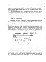
Figure 7.12: In an FDMA procedure several frequency channels are available
for the data transfer from the transponders to the reader
One option for load modulated RFID systems or backscatter systems is to use various
independent subcarrier frequencies for the data transmission from the transponders to
the reader.
One disadvantage of the FDMA procedure is the relatively high cost of the readers,
since a dedicated receiver must be provided for every reception channel. This
anticollision procedure, too, remains limited to a few specialised applications.
7.2.3 Time domain multiple access (TDMA)
The term time domain multiple access relates to techniques in which the entire
available channel capacity is divided between the participants chronologically. TDMA
procedures are particularly widespread in the field of digital mobile radio systems. In
RFID systems, TDMA procedures are by far the largest group of anticollision
procedures. We differentiate between transponder-driven and interrogator-driven
procedures (Figure 7.13).
This document was created by an unregistered ChmMagic, please go to to register it. Thanks.
Figure 7.13: Classification of time domain anticollision procedures according
to Hawkes (1997)
Transponder-driven procedures function asynchronously, since the reader does not
control the data transfer. This is the case, for example, in the ALOHA procedure,
which is described in more detail in Section 7.2.4. We also differentiate between
'switched off and 'non-switched' procedures depending upon whether a transponder is
switched off by a signal from the reader after successful data transfer.
Transponder-driven procedures are naturally very slow and inflexible. Most
applications therefore use procedures that are controlled by the reader as the master
(interrogator-driven). These procedures can be considered as synchronous, since all
transponders are controlled and checked by the reader simultaneously. An individual
transponder is first selected from a large group of transponders in the interrogation
zone of the reader using a certain algorithm and then the communication takes place
between the selected transponder and the reader (e.g. authentication, reading and
writing of data). Only then is the communication relationship terminated and a further
transponder selected. Since only one communication relationship is initiated at any
one time, but the transponders can be operated in rapid succession,
interrogator-driven procedures are also known as time duplex procedures.
Interrogator-driven procedures are subdivided into polling and binary search
procedures. All these procedures are based upon transponders that are identified by a
unique serial number:
The polling procedure requires a list of all the transponder serial numbers that can
possibly occur in an application. All the serial numbers are interrogated by the reader
one after the other, until a transponder with an identical serial number responds. This
procedure can, however, be very slow, depending upon the number of possible
transponders, and is therefore only suitable for applications with few known
transponders in the field.
Binary search procedures are the most flexible, and therefore the most common,
procedures. In a binary search procedure, a transponder is selected from a group by
intentionally causing a data collision in the transponder serial numbers transmitted to
the reader following a request command from the reader. If this procedure is to
succeed it is crucial that the reader is capable of determining the precise bit position of
a collision using a suitable signal coding system. A comprehensive description of the
binary search procedure is given in Section 7.2.4.
7.2.4 Examples of anticollision procedures
In the following subsections some of the more frequently used examples of
anticollision algorithms are discussed. The algorithms in the examples are
intentionally simplified such that the functional principle of the algorithm can be
understood without unnecessary complication.
7.2.4.1 ALOHA procedure
The simplest of all the multi-access procedures is the ALOHA procedure, which got its
name from the fact that this multi-access procedure was developed in the 1970s for
ALOHANET — a radio network for data transmission on Hawaii. As soon as a data
packet is available it is sent from the transponder to the reader. This is a
transponder-driven stochastic TDMA procedure.
The procedure is used exclusively with read-only transponders, which generally have
to transfer only a small amount of data (serial numbers), this data being sent to the
reader in a cyclical sequence. The data transmission time represents only a fraction of
the repetition time, so there are relatively long pauses between transmissions.
Furthermore, the repetition times for the individual transponders differ slightly. There
is therefore a certain probability that two transponders can transmit their data packets
This document was created by an unregistered ChmMagic, please go to to register it. Thanks.
at different times and the data packets will not collide with one another.
The time sequence of a data transmission in an ALOHA system is shown in Figure
7.14. The offered load G corresponds with the number of transponders transmitting
simultaneously at a certain point in time t0 (i.e. 0, 1, 2, 3, ). The average offered load
G is the average over an observation period T and is extremely simple to calculate
from the transmission duration τ of a data packet:
(7.1)
Figure 7.14: Definition of the offered load G and throughput S of an ALOHA
system— several transponders send their data packets at random points in
time. Now and then this causes data collisions, as a result of which the (data)
throughput S falls to zero for the data packets that have collided
where n = 1, 2, 3, is the number of transponders in the system and r
n
= 0, 1, 2, is
the number of data packets that are transmitted by transponder n during the
observation period.
The throughput s is 1 for the transmission duration of an error-free (collision-free) data
packet transmission. In all other cases, however, it is 0, since data was either not
transmitted or could not be read without errors due to a collision. For the (average)
throughput S of a transmission channel we find from the offered load G:
(7.2)
If we consider the throughput S in relation to the offered load G (see Figure 7.15) we
find a maximum of 18.4% at G = 0.5. For a smaller offered load the transmission
channel would be unused most of the time; if the offered load was increased the
number of collisions between the individual transponders would immediately increase
sharply. More than 80% of the channel capacity thus remains unused. However,
thanks to its simple implementation the ALOHA procedure is very well suited to use as
an anticollision procedure for simple read-only transponder systems. Other fields of
application for the ALOHA procedure are digital news networks such as packet radio,
which is used worldwide by amateur radio enthusiasts for the exchange of written
messages.
This document was created by an unregistered ChmMagic, please go to to register it. Thanks.
Figure 7.15: Comparison of the throughput curves of ALOHA and S-ALOHA.
In both procedures the throughput tends towards zero as soon as the
maximum has been exceeded
The probability of success q — the probability that an individual packet can be
transmitted without collisions — can be calculated from the average offered load G
and the throughput S (Fliege, 1996):
(7.3)
Derived from this equation, some datasheets provide figures on the time necessary to
reliably read all transponders in the interrogation zone — which depends upon the
number of transponders in the interrogation zone of a reader (TagMaster, 1997).
Table 7.1: Average time consumption for reading all transponders in the
interrogation zone of an example system
Number of transponders
in the interrogation zone
Average
(ms)
90%
reliability
(ms)
99.9%
reliability
(ms)
2150350500
3250550800
43007501000
54009001250
650012001600
765015002000
880018002700
The probability p(k) of k error-free data packet transmissions in the observation period
T can be calculated from the transmission duration τ of a data packet and the average
offered load G. The probability p(k) is a Poisson's distribution
[2]
with the mean value
G/τ:
(7.4)
This document was created by an unregistered ChmMagic, please go to to register it. Thanks.
7.2.4.2 Slotted ALOHA procedure
One possibility for optimising the relatively low throughput of the ALOHA procedure is
the slotted ALOHA procedure. In this procedure, transponders may only begin to
transmit data packets at defined, synchronous points in time (slots). The
synchronisation of all transponders necessary for this must be controlled by the
reader. This is therefore a stochastic, interrogator-driven TDMA anticollision
procedure.
The period in which a collision can occur (the collision interval) in this procedure is
only half as great as is the case for the simple ALOHA procedure.
Assuming that the data packets are the same size (and thus have the same
transmission duration τ) a collision will occur in the simple ALOHA procedure if two
transponders want to transmit a data packet to the reader within a time interval T ≤ 2τ.
Since, in the S-ALOHA procedure, the data packets may only ever begin at
synchronous time points, the collision interval is reduced to T = τ. This yields the
following relationship for the throughput S of the S-ALOHA procedure (Fliege, 1996).
(7.5)
In the S-ALOHA procedure there is a maximum throughput S of 36.8% for an offered
load G (see (Figure 7.15).
However, it is not necessarily the case that there will be a data collision if several data
packets are sent at the same time: if one transponder is closer to the reader than the
others that transponder may be able to override the data packets from other
transponders as a result of the greater signal strength at the reader. This is known as
the capture effect. The capture effect has a very beneficial effect upon throughput
behaviour (Figure 7.16). Decisive for this is the threshold b, which indicates the
amount by which a data packet must be stronger than others for it to be detected by
the receiver without errors (Borgonovo and Zorzi, 1997; Zorzi, 1995).
Figure 7.16: Throughput behaviour taking into account the capture effect with
thresholds of 3 dB and 10 dB
(7.6)
The practical application of a slotted ALOHA anticollision procedure will now be
This document was created by an unregistered ChmMagic, please go to to register it. Thanks.
considered in more detail on the basis of an example.
The transponder used must also have a unique serial number (i.e. one that has been
allocated only once). In this example we use an 8-bit serial number; this means that a
maximum of 256 transponders can be put into circulation if the uniqueness of serial
numbers is to be guaranteed.
We define a set of commands in order to synchronise and control the transponders
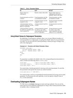
(Table 7.2).
Table 7.2: Command set for anticollision
REQUESTThis command synchronises all transponders in the
reader's interrogation zone and prompts the transponders
to transmit their serial numbers to the reader in one of the
time slots that follow. In our example there are always
three time slots available.
SELECT(SNR)Sends a (previously determined) serial number (SNR) to
the transponder as a parameter. The transponder with this
serial number is thereby cleared to perform read and write
commands (selected). Transponders with a different serial
number continue to react only to a REQUEST command.
READ_DATAThe selected transponder sends stored data to the reader.
(In a real system there are also commands for writing,
authentication, etc.)
A reader in wait mode transmits a REQUEST command at cyclical intervals. We now
bring five transponders into the interrogation zone of a reader at the same time
(Figure 7.17). As soon as the transponders have recognised the REQUEST
command, each transponder selects one of the three available slots by means of a
random-check generator, in order to send its own serial number to the reader. As a
result of the random selection of slots in our example there are collisions between the
transponders in slots 1 and 2. Only in slot 3 can the serial number of transponder 5 be
transmitted without errors.
Figure 7.17: Transponder system with slotted ALOHA anticollision procedure
If a serial number is read without errors, then the detected transponder can be
selected by the transmission of a SELECT command and then read or written without
further collisions with other transponders. If no serial number were detected at the first
attempt the REQUEST command is simply repeated cyclically.
When the previously selected transponder has been processed, further transponders
in the interrogation zone of the reader can be sought by means of a new REQUEST
This document was created by an unregistered ChmMagic, please go to to register it. Thanks.
command.
Dynamic S-ALOHA procedure
As we have established, the throughput S of an S-ALOHA system is maximised at a
offered load G of around 1. This means that there are the same number of
transponders in the interrogation zone of the reader as there are slots available. If
many further transponders are added, then the throughput quickly falls to zero. In the
worst case, no serial numbers can be detected even after an infinite number of
attempts because no transponder succeeds in being the only one to transmit in one
slot. This situation can be eased by the provision of a sufficient number of slots.
However, this reduces the performance of the anticollision algorithm, since the system
has to listen for possible transponders for the duration of all time slots — even if only a
single transponder is located in the interrogation zone of the reader. Dynamic
S-ALOHA procedures with a variable number of slots can help here.
One possibility is to transmit the number of slots (currently) available for the
transponders with each REQUEST command as an argument: in wait mode the
reader transmits REQUEST commands at cyclical intervals, which are followed by
only one or two slots for possible transponders. If a greater number of transponders
cause a bottleneck in both slots, then for each subsequent REQUEST command the
number of slots made available is increased (e.g. 1, 2, 4, 8, ) until finally an
individual transponder can be detected.
However, a large number of slots (e.g. 16, 32, 48, ) may also be constantly
available. In order to nevertheless increase performance, the reader transmits a
BREAK command as soon as a serial number has been recognised. Slots following
the BREAK commands are 'blocked' to the transmission of transponder addresses
(Figure 7.18).
Figure 7.18: Dynamic S-ALOHA procedure with BREAK command. After the
serial number of transponder 1 has been recognised without errors, the
response of any further transponders is suppressed by the transmission of a
BREAK command
7.2.4.3 Binary search algorithm
The implementation of a binary search algorithm requires that the precise bit position
of a data collision is recognised in the reader. In addition, a suitable bit coding is
required, so we will first compare the collision behaviour of NRZ (non-return-to-zero)
and Manchester coding (Figure 7.19). The selected system is an inductively coupled
transponder system with load modulation by an ASK modulated subcarrier. A 1 level in
the baseband coding switches the subcarrier on, and a 0 level switches it off.
This document was created by an unregistered ChmMagic, please go to to register it. Thanks.
Figure 7.19: Bit coding using Manchester and NRZ code
NRZ Code
The value of a bit is defined by the static level of the transmission channel within a bit
window (t
BIT
). In this example a logic 1 is coded by a static 'high' level; a logic 0 is
coded by a static 'low' level.
If at least one of the two transponders sends a subcarrier signal, then this is
interpreted by the reader as a 'high' level and in our example is assigned the logic
value 1. The reader cannot detect whether the sequence of bits it is receiving can be
traced back to the superposition of transmissions from several transponders or the
signal from a single transponder. The use of a block checksum (parity, CRC) can only
detect a transmission error 'somewhere' in the data block (see Figure 7.20).
Figure 7.20: Collision behaviour for NRZ and Manchester code. The
Manchester code makes it possible to trace a collision to an individual bit
Manchester code
The value of a bit is defined by the change in level (negative or positive transition)
within a bit window (t
BIT
). A logic 0 in this example is coded by a positive transition; a
logic 1 is coded by a negative transition. The 'no transition' state is not permissible
This document was created by an unregistered ChmMagic, please go to to register it. Thanks.
during data transmission and is recognised as an error.
If two (or more) transponders simultaneously transmit bits of different values then the
positive and negative transitions of the received bits cancel each other out, so that a
subcarrier signal is received for the duration of an entire bit. This state is not
permissible in the Manchester coding system and therefore leads to an error. It is thus
possible to trace a collision to an individual bit (see Figure 7.20).
We will use Manchester coding for our binary search algorithm. Let us now turn our
attention to the algorithm itself.
A binary search algorithm consists of a predefined sequence (specification) of
interactions (command and response) between a reader and several transponders
with the objective of being able to select any desired transponder from a large group.
For the practical realisation of the algorithm we require a set of commands that can be
processed by the transponder (Table 7.3). In addition, each transponder has a unique
serial number. In our example we are using an 8-bit serial number, so if we are to
guarantee the uniqueness of the addresses (serial numbers) a maximum of 256
transponders can be issued.
Table 7.3: Transponder commands for the binary search algorithm
REQUEST(SNR)This command sends a serial number to the
transponder as a parameter. If the transponder's own
serial number is less than (or equal to) the received
serial number, then the transponder sends its own
serial number back to the reader. The group of
transponders addressed can thus be preselected and
reduced.
SELECT_(SNR)Sends a (predetermined) serial number (SNR) to the
transponder as a parameter. The transponder with the
identical transponder address will become available for
the processing of other commands (e.g. reading and
writing data). This transponder is thus selected.
Transponders with different addresses will thereafter
only respond to a REQUEST command.
READ_DATAThe selected transponder sends stored data to the
reader. (In a real system there are also commands for
authentication or writing, debiting, crediting, etc.).
UNSELECTThe selection of a previously selected transponder is
cancelled and the transponder is 'muted'. In this state,
the transponder is completely inactive and does not
even respond to a REQUEST command. To reactivate
the transponder, it must be reset by temporarily
removing it from the interrogation zone of the reader (=
no power supply).
The use of the commands defined in Table 7.3 in a binary search algorithm will now
be demonstrated based upon a procedure with four transponders in the interrogation
zone of the reader. The transponders in our example possess unique serial numbers
in the range 00-FFh (= 0 - 255 dec. or 00000000 - 11111111 bin.) (Table 7.4).
This document was created by an unregistered ChmMagic, please go to to register it. Thanks.
Table 7.4: Serial numbers of the transponders used in this example
Transponder 110110010
Transponder 210100011
Transponder 310110011
Transponder 411100011
The first iteration of the algorithm begins with the transmission of the command
REQUEST (≤11111111) by the reader. The serial number 11111111b is the highest
possible in our example system using 8-bit serial numbers. The serial numbers of all
transponders in the interrogation zone of the reader must therefore be less than or
equal to 11111111b, so this command is answered by all transponders in the
interrogation zone of the reader (see Figure 7.21).
Figure 7.21: The different serial numbers that are sent back from the
transponders to the reader in response to the REQUEST command lead to a
collision. By the selective restriction of the preselected address range in
further iterations, a situation can finally be reached in which only a single
transponder responds
The precise synchronisation of all transponders, so that they begin to transmit their
serial numbers at exactly the same time, is decisive for the reliable function of the
binary tree search algorithm. Only in this manner is the determination of the precise bit
position of a collision possible.
At bit 0, bit 4 and bit 6 of the received serial number there is a collision (X) as a result
of the superposition of the different bit sequences of the responding transponders.
The occurrence of one or more collisions in the received serial numbers leads to the
conclusion that there are two or more transponders in the interrogation zone of the
reader. To be more precise, the received bit sequence 1X1X001X yields eight
possibilities for the serial numbers that have still to be detected (Table 7.5).
This document was created by an unregistered ChmMagic, please go to to register it. Thanks.
Table 7.5: Possible serial numbers after the evaluation of the received data and
taking into account the collisions (X) that have occurred in the first iteration. Four of
the possible transponder addresses (*) actually arise in our example
Bit number:76543210
Received data in the reader1X1X001X
Possible serial number A10100010
Possible serial number B*10100011
Possible serial number C*10110010
Possible serial number D*10110011
Possible serial number E11100010
Possible serial number F*11100011
Possible serial number G11110010
Possible serial number H11110011
Bit 6 is the highest value bit at which a collision has occurred in the first iteration. This
means that there is at least one transponder both in the range SNR ≥ 11000000b and
also in SNR ≤ 10111111b.
[3]
In order to be able to select an individual transponder,
we have to limit the search range for the next iteration according to the information
obtained. We decide arbitrarily to continue our search in the range ≤10111111b. To
do this we simply set bit 6 equal to 0 (highest value bit with collision), and ignore all
lower value bits by setting them to 1.
The general rule for limiting the search area (range) is shown in Table 7.6.
Table 7.6: General rule for forming the address parameter in a binary search tree. In
each case, bit (X) is the highest value bit of the received transponder address in
which a collision occurred in the previous iteration
Search command1st iteration rangenth iteration range =
REQUEST ≥ Range
0Bit(X) = 1, Bit(0 to X - 1) = 0
REQUEST ≤ Range
SNRmaxBit(X) = 0, Bit(0 to X - 1) = 1
After the reader has transmitted the command REQUEST (≤10111111), all
transponders that fulfil this condition will respond by sending their own serial numbers
to the reader. In our example these are the transponders 1, 2 and 3 (Figure 7.22).
There is now a collision (X) at bit 0 and bit 4 of the received serial number. From this
we can conclude that there are still at least two transponders in the search range of
the second iteration. The received bit sequence 101X001X still permits four options for
the serial numbers that remain to be detected (Table 7.7).
This document was created by an unregistered ChmMagic, please go to to register it. Thanks.
Table 7.7: Possible serial numbers in the search range after the evaluation of the
2nd iteration. The transponders marked (*) are actually present
Bit number:76543210
Received data at reader101X001X
Possible serial number A10100010
Possible serial number B*10100011
Possible serial number C*10110010
Possible serial number D*10110011
Figure 7.22: Binary search tree. An individual transponder can finally be
selected by a successive reduction of the range
The renewed appearance of collisions in the second iteration necessitates a further
restriction of the range in a third iteration. The use of the rule in Table 7.6 leads us to
the search range ≤10101111. The reader now transmits to the transponders the
command REQUEST (≤10101111). This condition is now only fulfilled by transponder
2 (10100011), which now responds to the command alone. We have thus detected a
valid serial number — a further iteration is not necessary.
By means of a subsequent SELECT command, transponder 2 is selected using the
detected transponder address and can now be read or written by the reader without
interference from other transponders. All other transponders are silent as only a
selected transponder responds to a write/read command — READ_DATA.
After the completion of the write/read operations, transponder 2 can be fully
deactivated by an UNSELECT command, so that it no longer responds to the next
REQUEST command. In this manner the number of iterations necessary for the
selection of an individual transponder can be gradually reduced if a large number of
transponders are 'waiting' for processing in the interrogation zone of the reader. In our
example, running the anticollision algorithm again would thus automatically lead to the
selection of one of the previously processed transponders 1, 3 or 4.
The average number of iterations L that are required to detect a single transponder
from a large number depends upon the total number of transponders N in the
interrogation zone of the reader, and can be calculated easily:
(7.7)
This document was created by an unregistered ChmMagic, please go to to register it. Thanks.
If only a single transponder is located in the interrogation zone of the reader, precisely
one iteration is required to detect the serial number of the transponder — a collision
does not occur in this case. If there is more than one transponder in the interrogation
zone of the reader, then the average number of iterations increases quickly, following
the curve shown in Figure 7.23.
Figure 7.23: The average number of iterations needed to determine the
transponder address (serial number) of a single transponder as a function of
the number of transponders in the interrogation zone of the reader. When
there are 32 transponders in the interrogation zone an average of six
iterations are needed, for 65 transponders on average seven iterations, for
128 transponders on average eight iterations, etc.
Dynamic binary search procedure
In the binary search procedure described above, both the search criterion and the
serial numbers of the transponders are always transmitted at their full length. In
practice, however, the serial numbers of transponders do not consist of one byte, as in
our example, but, depending upon the system, can be up to 10 bytes long, which
means that a large quantity of data must be transferred in order to select an individual
transponder. If we investigate the data flow between the reader and the individual
transponders in more detail (Figure 7.24) we find that:
Figure 7.24: Reader's command (nth iteration) and transponder's response
when a 4-byte serial number has been determined. A large part of the
transmitted data in the command and response is redundant (shown in grey).
X is used to denote the highest value bit position at which a bit collision
occurred in the previous iteration
Bits (X - 1) to 0 of the command contain no additional information for
the transponder since they are always set to 1.
Bits N to X of the serial number in the transponder's response
contain no additional information for the reader, as they are already
known and predetermined.
This document was created by an unregistered ChmMagic, please go to to register it. Thanks.
We therefore see that complementary parts of the transmitted serial numbers are
redundant and actually do not need to be transmitted. This quickly leads us to an
optimized algorithm. Instead of transmitting the full length of the serial numbers in both
directions, the transfer of a serial number or the search criterion is now simply split
according to bit (X). The reader now sends only the known part (N - X) of the serial
number to be determined as the search criterion in the REQUEST command and then
interrupts the transmission. All transponders with serial numbers that correspond to
the search criterion in the bits (N - X) now respond by transmitting the remaining bits
((X - 1) - 0) of their serial numbers. The transponders are informed of the number of
subsequent bits by an additional parameter (NVB = number of valid bits) in the
REQUEST command.
Let us now illustrate in more detail the sequence of a dynamic binary search algorithm
on the basis of the example in Figure 7.25. We use the same transponder serial
numbers as in the previous example. Since we are applying the rule (Table 7.6)
unchanged, the sequence of individual iterations corresponds with that of the previous
example. In contrast, however, the amount of data to be transferred — and thus the
total time needed — can be reduced by up to 50%.
Figure 7.25: The dynamic binary search procedure avoids the transmission of
redundant parts of the serial number. The data transmission time is thereby
noticeably reduced
[1]
If the angle between two transponders is greater than the beam width of the
directional antennas used a transmission channel can be used several times.
[2]
A random number has a Poisson's distribution if it takes on the countable number of
possible values k = 0, 1, 2, with a probability p(k) = e
-λ
.
[3]
Bit 6 is printed in bold type in each case. A careful evaluation of the results in Table
7.5 leads to the conclusion that there is at least one transponder in the ranges
11100010b-11110011b and 10100010b-10110011b.
This document was created by an unregistered ChmMagic, please go to to register it. Thanks.
Chapter 8: Data Security
Overview
RFID systems are increasingly being used in high security applications, such
as access systems and systems for making payments or issuing tickets.
However, the use of RFID systems in these applications necessitates the use
of security measures to protect against attempted attacks, in which people try
to trick the RFID system in order to gain unauthorised access to buildings or
avail themselves of services (tickets) without paying. This is nothing new — we
only have to look to myths and fairy stories to find examples of attempts to
outsmart security systems. For example, Ali Baba was able to gain access to
the supposedly secure hideout of the 40 thieves by discovering the secret
password.
Modern authentication protocols also work by checking knowledge of a secret
(i.e. a cryptographic key). However, suitable algorithms can be employed to
prevent the secret key being cracked. High security RFID systems must have a
defence against the following individual attacks:
Unauthorised reading of a data carrier in order to duplicate
and/or modify data.
The placing of a foreign data carrier within the interrogation
zone of a reader with the intention of gaining unauthorised
access to a building or receiving services without payment.
Eavesdropping into radio communications and replaying the
data, in order to imitate a genuine data carrier ('replay and
fraud').
When selecting a suitable RFID system, consideration should be given to
crypto-logical functions. Applications that do not require a security function (e.g.
industrial automation, tool recognition) would be made unnecessarily
expensive by the incorporation of cryptological procedures. On the other hand,
in high security applications (e.g. ticketing, payment systems) the omission of
cryptological procedures can be a very expensive oversight if manipulated
transponders are used to gain access to services without authorisation.
This document was created by an unregistered ChmMagic, please go to to register it. Thanks.
8.1 Mutual Symmetrical Authentication
Mutual authentication between reader and transponder is based upon the
principle of three-pass mutual authentication in accordance with ISO 9798-2, in
which both participants in the communication check the other party's
knowledge of a secret (secret cryptological key).
In this procedure, all the transponders and receivers that form part of an
application are in possession of the same secret cryptological key K (→
symmetrical procedure). When a transponder first enters the interrogation zone
of a reader it cannot be assumed that the two participants in the
communication belong to the same application. From the point of view of the
reader, there is a need to protect the application from manipulation using
falsified data. Likewise, on the part of the transponder there is a need to protect
the stored data from unauthorised reading or overwriting.
The mutual authentication procedure begins with the reader sending a GET
CHALLENGE command to the transponder. A random number R
A
is then
generated in the transponder and sent back to the reader (response →
challenge-response procedure). The reader now generates a random number
R
B
. Using the common secret key K and a common key algorithm e
k
, the
reader calculates an encrypted data block (token 1), which contains both
random numbers and additional control data, and sends this data block to the
transponder.
Token 1 = e
K
(R
B
||R
A
||ID
A
||Text1)
The received token 1 is decrypted in the transponder and the random number
R'
A
contained in the plain text is compared to the previously transmitted R
A
. If
the two figures correspond, then the transponder has confirmed that the two
common keys correspond. Another random number R
A2
is generated in the
transponder and this is used to calculate an encrypted data block (token 2),
which also contains R
B
and control data. Token 2 is sent from the transponder
to the reader.
Token 2 = e
K
(R
A2
||R
B
||Text2)
The reader decrypts token 2 and checks whether R
B
, which was sent
previously, corresponds with R'
B
, which has just been received. If the two
figures correspond, then the reader is satisfied that the common key has been
proven. Transponder and reader have thus ascertained that they belong to the
same system and further communication between the two parties is thus
legitimised (Figure 8.1).
This document was created by an unregistered ChmMagic, please go to to register it. Thanks.
Figure 8.1: Mutual authentication procedure between transponder and
reader
To sum up, the mutual authentication procedure has the following advantages:
The secret keys are never transmitted over the airwaves,
only encrypted random numbers are transmitted.
Two random numbers are always encrypted simultaneously.
This rules out the possibility of performing an inverse
transformation using R
A
to obtain token 1, with the aim of
calculating the secret key.
The token can be encrypted using any algorithm.
The strict use of random numbers from two independent
sources (transponder, reader) means that recording an
authentication sequence for playback at a later date (replay
attack) would fail.
A random key (session key) can be calculated from the
random numbers generated, in order to cryptologically
secure the subsequent data transmission.
This document was created by an unregistered ChmMagic, please go to to register it. Thanks.
8.2 Authentication Using Derived Keys
One disadvantage of the authentication procedure described in Section 8.1 is that all
transponders belonging to an application are secured using an identical cryptological
key K. For applications that involve vast quantities of transponders (e.g. the ticketing
system for the public transport network, which uses several million transponders) this
represents a potential source of danger. Because such transponders are accessible to
everyone in uncontrolled numbers, the small probability that the key for a transponder
will be discovered must be taken into account. If this occurred, the procedure
described above would be totally open to manipulation.
A significant improvement on the authentication procedure described can be achieved
by securing each transponder with a different cryptological key. To achieve this, the
serial number of each transponder is read out during its production. A key K
X
is
calculated (→ derived) using a cryptological algorithm and a master key K
M
, and the
transponder is thus initialised. Each transponder thus receives a key linked to its own
ID number and the master key K
M
.
The mutual authentication begins by the reader requesting the ID number of the
transponder (Figure 8.2). In a special security module in the reader, the SAM (security
authentication module), the transponder's specific key is calculated using the master
key K
M
, so that this can be used to initiate the authentication procedure. The SAM
normally takes the form of a smart card with contacts incorporating a
cryptoprocessor, which means that the stored master key can never be read.
Figure 8.2: In an authentication procedure based upon derived keys, a key
unique to the transponder is first calculated in the reader from the serial
number (ID number) of the transponder. This key must then be used for
authentication
This document was created by an unregistered ChmMagic, please go to to register it. Thanks.
8.3 Encrypted Data Transfer
Chapter 7 described methods of dealing with interference caused by physical
effects during data transmission. Let us now extend this model to a potential
attacker. We can differentiate between two basic types of attack. Attacker 1
behaves passively and tries to eavesdrop into the transmission to discover
confidential information for wrongful purposes. Attacker 2, on the other hand,
behaves actively to manipulate the transmitted data and alter it to his benefit.
See Figure 8.3.
Figure 8.3: Attempted attacks on a data transmission. Attacker 1
attempts to eavesdrop, whereas attacker 2 maliciously alters the data
Cryptological procedures are used to protect against both passive and active
attacks. To achieve this, the transmitted data (plain text) can be altered
(encrypted) prior to transmission so that a potential attacker can no longer draw
conclusions about the actual content of the message (plain text).
Encrypted data transmission always takes place according to the same pattern.
The transmission data (plain text) is transformed into cipher data (cipher text)
(→ encryption, ciphering) using a secret key K and a secret algorithm. Without
knowing the encryption algorithm and the secret key K a potential attacker is
unable to interpret the recorded data. It is not possible to recreate the
transmission data from the cipher data.
The cipher data is transformed back to its original form in the receiver using the
secret key K' and the secret algorithm (→ decryption, deciphering). See Figure
8.4.
This document was created by an unregistered ChmMagic, please go to to register it. Thanks.
Figure 8.4: By encrypting the data to be transmitted, this data can be
effectively protected from eavesdropping or modification
If the keys K for ciphering and K' for deciphering are identical (K = K') or in a
direct relationship to each other, the procedure is a symmetrical key procedure.
If knowledge of the key K is irrelevant to the deciphering process, the
procedure is an asymmetrical key procedure. RFID systems have for a long
time used only symmetrical procedures, therefore we will not describe other
procedures in further detail here.
If each character is individually encrypted prior to transmission, the procedure
is known as sequential ciphering (or stream ciphering). If, on the other hand,
several characters are incorporated into a block then we talk of a block cipher.
Because block ciphers are generally very calculation intensive, they play a
less important role in RFID systems. Therefore the emphasis is placed on
sequential ciphers in what follows.
A fundamental problem of all cryptological procedures is the secure distribution
of the secret key K, which must be known by the authorised communication
participants prior to the start of the data transfer procedure.
8.3.1 Stream cipher
Sequential ciphers or stream ciphers are encryption algorithms in which the
sequence of plain text characters is encrypted sequentially using a different
function for every step (Fumy, 1994). The ideal realisation of a stream cipher is
the so-called one-time pad, also known as the Vernam cipher after its
discoverer (Longo, 1993).
In this procedure a random key K is generated, for example using dice, prior to
the transmission of encrypted data, and this key is made available to both
parties (Figure 8.5). The key sequence is linked with the plain text sequence by
the addition of characters or using XOR gating. The random sequence used as
a key must be at least as long as the message to be encrypted, because
periodic repetitions of a typically short key in relation to the plain text would
permit cryptoanalysis and thus an attack on the transmission. Furthermore, the
key may only be used once, which means that an extremely high level of
security is required for the secure distribution of keys. Stream ciphering in this
form is completely impractical for RFID systems.
This document was created by an unregistered ChmMagic, please go to to register it. Thanks.
Figure 8.5: In the one-time pad, keys generated from random numbers
(dice) are used only once and then destroyed (wastepaper basket).
The problem here is the secure transmission of the key between sender
and recipient
To overcome the problem of key generation and distribution, systems have
been created based upon the principle of the one-time pad stream cipher, that
use a so-called pseudorandom sequence instead of an actual random
sequence. Pseudorandom sequences are generated using so-called
pseudorandom generators.
Figure 8.6 shows the fundamental principle of a sequential cipher using a
pseudorandom generator: because the encryption function of a sequential
cipher can change (at random) with every character, the function must be
dependent not only upon the current input character but also upon an
additional feature, the internal state M. This internal state M is changed after
every encryption step by the state transformation function g(K). The
pseudorandom generator is made up of the components M and g(K). The
security of the cipher depends principally upon the number of internal states M
and the complexity of the transformation function g(K). The study of sequential
ciphers is thus primarily concerned with the analysis of pseudorandom
generators.
Figure 8.6: The principle underlying the generation of a secure key by a
pseudorandom generator
The encryption function f(K) itself, on the other hand, is generally very simple
and can only comprise an addition or XOR logic gating (Fumy, 1994; Glogau,
This document was created by an unregistered ChmMagic, please go to to register it. Thanks.
1994).
From a circuitry point of view, pseudorandom generators are realised by state
machines. These consist of binary storage cells, so-called flip-flops. If a state
machine has n storage cells then it can take on 2
n
different internal M states.
The state transformation function g(K) is represented by combinatorial logic (a
more detailed explanation of the functionality of state machines can be found in
Chapter 10). The implementation and development of pseudorandom
generators can be greatly simplified if we restrict ourselves to the use of linear
feedback shift registers (Figure 8.7).
Figure 8.7: Basic circuit of a pseudorandom generator incorporating a
linear feedback shift register (LFSR)
A shift register is realised by the serial connection of flip-flops (output
n
is
connected with input
n+1
) and the parallel connection of all timing inputs. The
content of the flip-flop cell is shifted forwards by one position with every timing
pulse. The content of the last flip-flop is output (Golomb, 1982; Rueppel, 1986).
This document was created by an unregistered ChmMagic, please go to to register it. Thanks.
Chapter 9: Standardisation
The development of standards is the responsibility of the technical committee
of the ISO. The ISO is the worldwide union of national standardisation
institutions, such as DIN (Germany) and ANSI (USA).
The description of standards in this chapter merely serves to aid our technical
understanding of the RFID applications dealt with in this book and no attempt
has been made to describe the standards mentioned in their entirety.
Furthermore, standards are updated from time to time and are thus subject to
change. When working with the RFID applications in question the reader
should not rely on the parameters specified in this chapter. We recommend
that copies of the original versions in question are procured. The necessary
addresses are listed in Section 14.2 at the end of this book.
9.1 Animal Identification
ISO standards 11784, 11785 and 14223 deal with the identification of animals
using RFID systems.
ISO 11784: 'Radio-frequency identification of animals —
Code structure'
ISO 11785: 'Radio-frequency identification of animals —
Technical concept'
ISO 14223: 'Radio-frequency identification of animals —
Advanced transponders':
Part 1: Air interface
Part 2: Code and command structure
Part 3: Applications
The constructional form of the transponder used is not specified in the
standards and therefore the form can be designed to suit the animal in
question. Small, sterile glass transponders that can be injected into the fatty
tissues of the animal are normally used for the identification of cows, horses
and sheep. Ear tags or collars are also possible.
9.1.1 ISO 11784 - Code structure
The identification code for animals comprises a total of 64 bits (8 bytes). Table
9.1 shows the significance of the individual bits.
This document was created by an unregistered ChmMagic, please go to to register it. Thanks.
Table 9.1: Identification codes for animals
Bit
number
InformationDescription
1Animal
(1)/non-animal
application (0)
Specifies whether the
transponder is used for animal
identification or for other
purposes
2–15ReservedReserved for future applications
16Data block (1)
follows/no data
block (0)
Specifies whether additional
data will be transmitted after the
identification code
17–26Country code as per
ISO 3166
Specifies the country of use (the
code 999 describes a test
transponder)
27–64National
identification code
Unique, country-specific
registration number
The national identification code should be managed by the individual countries.
Bits 27 to 64 may also be allocated to differentiate between different animal
types, breeds, regions within the country, breeders etc., but this is not specified
in this standard.
9.1.2 ISO 11785 - Technical concept
This standard defines the transmission method for the transponder data and
the reader specifications for activating the data carrier (transponder). A central
aim in the development of this standard was to facilitate the interrogation of
transponders from an extremely wide range of manufacturers using a common
reader. A reader for animal identification in compliance with the standard
recognises and differentiates between transponders that use a full/half duplex
system (load modulation) and transponders that use a sequential system.
9.1.2.1 Requirements
The standard specifies the operating frequency for the reader as 134.2 kHz ±
1.8 kHz. The emitted field provides a power supply for the transponder and is
therefore termed the 'activation field'.
The activation field is periodically switched on for 50 ms at a time and then
switched off for 3 ms (1 in Figure 9.1). During the 50 ms period when it is
switched on it waits for the response from a full/half duplex transponder — a
sequential transponder in the field requires the activation field to charge up its
charging capacitor.
This document was created by an unregistered ChmMagic, please go to to register it. Thanks.
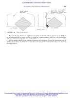
Figure 9.1: Path of the activation field of a reader over time— no
transponder in interrogation zone, full/half duplex (= load
modulated) transponder in interrogation zone, sequential
transponder in the interrogation zone of the reader
If a full/half duplex transponder is present within the range of the activation
field, then this transponder sends its data during the operating interval of the
field (2 in Figure 9.1). While data is being received the operating interval can
be extended to 100 ms if the data transfer is not completed within the first 50
ms.
A sequential transponder in the range of the activation field (3 in Figure 9.1)
begins to transmit data within the 3 ms pause. The duration of the pause is
extended to a maximum of 20 ms to permit the complete transmission of a
data record.
If portable or stationary readers are operated in the vicinity of one another,
then there is a high probability that a reader will emit its activation field during
the 3 ms pause of the other reader. This would result in neither of the readers
being able to receive the data signal of a sequential transponder. Due to the
relatively strong activation field in comparison to the field strength of a
sequential transponder this effect occurs in a multiple of the reader's normal
read radius. Appendix C of the standard therefore describes procedures for the
synchronisation of several readers to circumvent this problem.
Portable and stationary readers can be tested for the presence of a second
reader (B in Figure 9.2) in the vicinity by extending the pause duration to 30
ms. If the activation field of a second reader (B) is received within the 30 ms
pause, then the standard stipulates that the activation field of the reader (A)
should be switched on for a maximum of 50 ms as soon as the previously
detected reader (B) switches its activation field on again after the next 3 ms
pause. In this manner, a degree of synchronisation can be achieved between
two neighbouring readers. Because data is only transmitted from the
transponder to the reader (and the activation field thus always represents an
unmodulated HF field), an individual transponder can be read by two portable
readers simultaneously. To maintain the stability of the synchronisation, every
tenth pause cycle is extended from 3 ms to 30 ms to detect any other readers
that have recently entered the area.
This document was created by an unregistered ChmMagic, please go to to register it. Thanks.