all in one cisco ccie lab study guide second edition phần 7 ppsx
Bạn đang xem bản rút gọn của tài liệu. Xem và tải ngay bản đầy đủ của tài liệu tại đây (699.79 KB, 89 trang )
Monitoring and Testing the Configuration
From RouterA, monitor the policy routing using the debug ip policy command. Telnet from RouterA to
152.1.1.1. What follows is the output from the debug command; note that the telnet packet matched item 20 of
route map lab1 and was forwarded to 151.1.1.2.
IP: s=151.1.1.1 (local), d=152.1.1.1, len 44, policy match
IP: route map lab1, item 20, permit
IP: s=151.1.1.1 (local), d=152.1.1.1 (Serial1), len 44, policy routed
IP: local to Serial1 151.1.1.2
From RouterA, use the extended telnet command to send a HTTP packet to 152.1.1.2. To use this command,
simply type in Telnet 152.1.1.1 www at the privileged level. What follows is the output from the debug
command; note that the HTTP packet matched item 10 of route map lab1 and was forwarded to 150.1.1.2.
IP: s=151.1.1.1 (local), d=152.1.1.1, len 44, policy match
IP: route map lab1, item 10, permit
IP: s=151.1.1.1 (local), d=152.1.1.1 (Serial0), len 44, policy routed
IP: local to Serial0 150.1.1.2
Lab #67: Load Balancing Across Default Routes
Equipment Needed
The following equipment is needed to perform this lab exercise:
Two Cisco routers each having one Ethernet port and two serial ports•
One Cisco router with one Ethernet port•
Cisco IOS 11.0 or higher•
A PC running a terminal emulation program for connecting to the console port of the routers•
Two Cisco DTE/DCE cross over cables•
Cisco rolled cable•
One Ethernet crossover cable or an Ethernet hub and two straight−through Ethernet cables•
Configuration Overview
This configuration provides two end users with equal access to two different service providers. As per Figure
13−5, RouterA will route packets arriving on Ethernet 0 from the source 192.1.1.11 to default interface S0 if
no explicit route for the packets' destination is in the routing table. Packets arriving from 192.1.1.12 are sent
to default interface S1 if the router has no explicit route for the packets destination.
Figure 13−5: Load balancing across default routes
This lab uses the default interface command, which differs from the next hop interface and next hop IP
address set commands we used in previous labs. The next hop set commands send the matching packet out
that interface or to that IP address regardless of the routing table. The default interface command only sends
the packet out that particular interface if there is no explicit route in the routing table.
Note When using the default interface set command, the router will first check the routing table for an
explicit route. If there is no explicit route available to the destination address of the packet being
considered for policy routing, then the router will route the packet out the default interface.
507
Router Configurations
The configurations for the two routers in this example are as follows (key policy routing configurations are
highlighted in bold).
RouterA
version 11.2
service udp−small−servers
service tcp−small−servers
!
hostname RouterA
!
!
interface Ethernet0
ip address 192.1.1.10 255.255.255.0
ip policy route−map lab1 ← Enables policy routing on interface E0 and
identifies the route map lab1, which will be
applied to the packet
!
interface Serial0
ip address 150.1.1.1 255.255.255.0
no fair−queue
!
interface Serial1
ip address 151.1.1.1 255.255.255.0
!
router rip
network 150.1.0.0
network 151.1.0.0
network 192.1.1.0
!
no ip classless
access−list 1 permit 192.1.1.11
access−list 2 permit 192.1.1.12
route−map lab1 permit 10 ← Defines the route map lab1, the number specifies the
order of the route maps. This is referred to as item
10 of route map lab1
match ip address 1 ← This defines the match criteria tied to access list 1
set default interface Serial0 ← Sets the default interface to S0
!
route−map lab1 permit 20 ← Defines the route map lab1, the number specifies the
order of the route maps. This is referred to as item
10 of route map lab1
match ip address 2 ← This defines the match criteria tied to access list 1
set default interface Serial1 ← Sets the default interface to S0
!
!
line con 0
line aux 0
line vty 0 4
login
!
end
RouterB
version 11.2
service udp−small−servers
service tcp−small−servers
!
hostname routerb
!
!
!
508
interface Loopback0
ip address 152.1.1.1 255.255.255.0
!
interface Ethernet0
no ip address
shutdown
!
interface Serial0
ip address 150.1.1.2 255.255.255.0
clockrate 500000 ← Acts as DCE providing clock
!
interface Serial1
ip address 151.1.1.2 255.255.255.0
clockrate 500000 ← Acts as DCE providing clock
!
router rip
passive−interface Serial0 ← Prevents RIP updates from being sent to RouterA
passive−interface Serial1
network 152.1.0.0
network 151.1.0.0
network 150.1.0.0
!
!
line con 0
line 1 16
transport input all
line aux 0
transport input all
line vty 0 4
login
!
end
RouterC
version 11.2
service udp−small−servers
service tcp−small−servers
!
hostname routerc
!
interface Ethernet0
ip address 192.1.1.12 255.255.255.0 secondary
ip address 192.1.1.11 255.255.255.0
!
interface Serial0
no ip address
shutdown
!
ip route 0.0.0.0 0.0.0.0 192.1.1.10 ← Sets the default route
!
!
line con 0
line 1 16
line aux 0
line vty 0 4
login
!
end
Monitoring and Testing the Configuration
When using the default interface set command, the router will first check the routing table for an explicit
route. RouterA does not have an explicit route to 152.1.1.1 because RouterB suppresses RIP updates with the
509
passive interface commands.
From RouterA, monitor the policy routing using the debug ip policy command. From RouterC, ping
152.1.1.1 using the extended ping command to source the packet from 192.1.1.11. What follows is the output
from the debug command on RouterA; note that the source address 192.1.1.11 matched item 10 of route map
lab1 and was forwarded out interface S1.
IP: s=192.1.1.11 (Ethernet0), d=152.1.1.1, len 100, policy match
IP: route map lab1, item 10, permit
IP: s=192.1.1.11 (Ethernet0), d=152.1.1.1 (Serial0), len 100, policy routed
IP: Ethernet0 to Serial0 152.1.1.1
From RouterA, ping 152.1.1.1, sourcing the packet from 192.1.1.12. What follows is the output from the
debug command on RouterA; note that the source address 192.1.1.12 matched item 20 of route map lab1 and
was forwarded out interface S0.
IP: s=192.1.1.12 (Ethernet0), d=152.1.1.1, len 100, policy match
IP: route map lab1, item 20, permit
IP: s=192.1.1.12 (Ethernet0), d=152.1.1.1 (Serial1), len 100, policy routed
IP: Ethernet0 to Serial1 152.1.1.1
On RouterB remove the passive interface commands to allow RIP updates to be sent to RouterA. Now that
RouterA has a route for 152.1.1.1 learned via RIP, it will not policy−route the packet. Remember when using
the default interface set command, the router will first check the routing table for an explicit route. If the
router has a route to the destination, the packet is forwarded using that route; if there is no explicit route
available to the destination address, then the router will route the packet out the default interface, which is set
using policy routing.
routerb(config)#router rip
routerb(config−router)#no passive−interface s0
routerb(config−router)#no passive−interface s1
From RouterC, ping 152.1.1.1. What follows is the output from the debug ip policy command on RouterA;
note that the packet matched item 20 in route map lab1. However, the set policy was rejected because the
routing table has an explicit route to 152.1.1.1.
IP: s=192.1.1.12 (Ethernet0), d=152.1.1.1, len 100, policy match
IP: route map lab1, item 20, permit
IP: s=192.1.1.12 (Ethernet0), d=152.1.1.1 (Serial1), len 100, policy rejected −
normal forwarding
Troubleshooting Policy Routing
The Cisco IOS provides many tools for troubleshooting policy routing. What follows is a list of key
commands along with sample output from each.
{show ip policy} This privileged exec command displays which route map is used on which interface.
RouterA#show ip policy
Interface Route map
Ethernet0 lab1
{show route−map} This privileged exec command displays configured route maps. This command allows
you to view the policies defined by each route map. The command also shows how many packets matched the
policy clauses.
RouterA#show route−map
route−map lab1, permit, sequence 10
Match clauses:
ip address (access−lists): 1
510
Set clauses:
default interface Serial0
Policy routing matches: 129 packets, 14526 bytes
route−map lab1, permit, sequence 20
Match clauses:
ip address (access−lists): 2
Set clauses:
default interface Serial1
Policy routing matches: 205 packets, 23370 bytes
{debug ip policy} This exec command helps you determine what policy routing is doing. It displays
information about whether a packet matches the criteria, and if so, the resulting routing information for the
packet. The first line indicates that a packet matched the policy. The second line indicates the item of the route
map that the packet matched. In this case, the packet matches item 20 in route map lab1. Line three indicates
that the packet was policy−routed out interface S0.
IP: s=192.1.1.11 (Ethernet0), d=152.1.1.1, len 100, policy match
IP: route map lab1, item 10, permit
IP: s=192.1.1.11 (Ethernet0), d=152.1.1.1 (Serial0), len 100, policy routed
IP: Ethernet0 to Serial0 152.1.1.1
{show ip local policy} This exec command displays any route maps used for local policy routing. By default,
packets that are generated by the router are not policy−routed. Local policy routing must be enabled on the
router using the IP local policy route−map command.
RouterA#show ip local policy
Local policy routing is enabled, using route map lab1
route−map lab1, permit, sequence 10
Match clauses:
ip address (access−lists): 1
Set clauses:
default interface Serial0
Policy routing matches: 129 packets, 14526 bytes
route−map lab1, permit, sequence 20
Match clauses:
ip address (access−lists): 2
Set clauses:
default interface Serial1
Policy routing matches: 205 packets, 23370 bytes
Conclusion
Policy−based routing provides network administrators a way to implement packet forwarding according to
other criteria than traditional destination−based routing. The following are some of the potential applications
for policy routing:
Carrier selection is available for WAN transmissions or internal data path selection for Internet
access.
•
ISPs can use policy routing to provide equal access to multiple carrier networks.•
Policy−based routing can be used to set either the precedence or type−of−service bits in an IP
datagram, which can be used to provide Quality of Service (QOS) across the backbone.
•
Policy−based routing can be used to separate high− and low−priority traffic over separate links.•
511
Chapter 14: Cisco Discovery Protocol
Overview
Topics Covered in This Chapter
CDP overview•
Cisco CDP WAN configuration•
Cisco CDP LAN configuration•
CDP troubleshooting•
Introduction
Cisco Discovery Protocol (CDP) is a Cisco proprietary protocol that is used for neighbor discovery. CDP is
supported across the entire Cisco product line. CDP is very helpful in debugging situations. For example, it
can be used to verify that a given router is connected to the proper port number on its neighbor. This chapter
will examine CDP in detail.
Cisco Discovery Protocol Overview
CDP runs on all Cisco routers and switches. It can run over any physical media and over any protocol. Unlike
a routing protocol that shows a next−hop destination port for all known networks, CDP will only show
information for directly connected neighbors. It is most useful for verifying that a router is connected to the
proper port of its neighbor.
Figure 14−1 gives an overview of the information that CDP can provide. A CDP−enabled router will be able
to learn directly connected neighbor port and hostname information. Additional information such as the
neighbor's hardware model number and capabilities are also reported.
Figure 14−1: CDP overview
How Does CDP Work?
A CDP−enabled router sends out a periodic multicast packet containing a CDP update. The time between
these CDP updates is determined by the cdp timer command, the timer value default being 60 seconds.
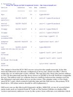
The following code shows a captured CDP packet. A Network Associates sniffer was put on an Ethernet LAN
that also had several Cisco routers connected to it. As can be seen from the packet trace, the router sending the
packet includes important information including:
Router hostname (Cisco1)•
Router port information (Ethernet 0/0)•
IOS version information (11.2(7a)P)•
IOS platform information (C3620−I−M)•
Hardware version information (Cisco 3600)•
512
Although neighbor router IOS version, IOS platform, and hardware version are not critical pieces of
information, neighbor router hostname and neighbor router port information are critical for debug purposes.
The use of the show cdp neighbor command is most useful in debug situations where one needs to verify
what router and router port a given router is connected to.
Packet 1 captured at 12/21/1998 12:19:37 AM; Packet size is 318(0x13e)bytes
Relative time: 000:00:35.858
Delta time: 0.000.000
ETHER: Address: 00−E0−1E−5B−0A−81 —−>01−00−0C−CC−CC−CC
Logical Link Control
SSAP Address: 0xAA, CR bit = 0 (Command)
DSAP Address: 0xAA, IG bit = 0 (Individual address)
Unnumbered frame: UI
SubNetwork Access Protocol
Organization code: 0x00000c
Type: Custom Defined
Data:
0000: 01 b4 aa 2b 00 01 00 0a 43 69 73 63 6f 31 00 02 | a+ Cisco1
0010: 00 11 00 00 00 01 01 01 cc 00 04 c1 01 01 01 00 | I A
0020: 03 00 0f 45 74 68 65 72 6e 65 74 30 2f 30 00 04 | Ethernet0/0
0030: 00 08 00 00 00 01 00 05 00 e4 43 69 73 63 6f 20 | aCisco
0040: 49 6e 74 65 72 6e 65 74 77 6f 72 6b 20 4f 70 65 | Internetwork Ope
0050: 72 61 74 69 6e 67 20 53 79 73 74 65 6d 20 53 6f | rating System So
0060: 66 74 77 61 72 65 20 0a 49 4f 53 20 28 74 6d 29 | ftware .IOS (tm)
0070: 20 33 36 30 30 20 53 6f 66 74 77 61 72 65 20 28 | 3600 Software (
0080: 43 33 36 32 30 2d 49 2d 4d 29 2c 20 56 65 72 73 | C3620−I−M), Vers
0090: 69 6f 6e 20 31 31 2e 32 28 37 61 29 50 2c 20 53 | ion 11.2(7a)P, S
00a0: 48 41 52 45 44 20 50 4c 41 54 46 4f 52 4d 2c 20 | HARED PLATFORM,
00b0: 52 45 4c 45 41 53 45 20 53 4f 46 54 57 41 52 45 | RELEASE SOFTWARE
00c0: 20 28 66 63 31 29 0a 43 6f 70 79 72 69 67 68 74 | (fc1).Copyright
00d0: 20 28 63 29 20 31 39 38 36 2d 31 39 39 37 20 62 | (c) 1986−1997 b
00e0: 79 20 63 69 73 63 6f 20 53 79 73 74 65 6d 73 2c | y cisco Systems,
00f0: 20 49 6e 63 2e 0a 43 6f 6d 70 69 6c 65 64 20 57 | Inc Compiled W
0100: 65 64 20 30 32 2d 4a 75 6c 2d 39 37 20 30 38 3a | ed 02−Jul−97 08:
0110: 32 35 20 62 79 20 63 63 61 69 00 06 00 0e 63 69 | 25 by ccai ci
0120: 73 63 6f 20 33 36 32 30 | sco 3620
Commands Discussed in This Chapter
cdp enable•
cdp run•
cdp timer•
clear cdp counters•
clear cdp table•
show cdp interface•
show cdp neighbor•
show cdp traffic•
debug cdp [packets] [ip] [adjacency] [events]•
Definitions
cdp enable: This interface command is used to enable CDP on a particular interface. Since CDP is enabled
by default, this command will not be shown in the router configuration.
cdp run: This global command enables CDP on the entire router. Using the no cdp run command will
disable any CDP on the router. Since CDP is enabled by default, the cdp run command will not shown in the
router configuration.
513
cdp timer: This global command specifies how often the router sends CDP updates. The default time
between CDP updates is 60 seconds.
clear cdp counters: This privileged exec command causes the router's CDP traffic counters to be reset.
clear cdp table: This privileged exec command causes the router's CDP table to be cleared. When this
occurs, the show cdp neighbor command will not show any information until another CDP update is received
from a neighbor router.
show cdp interface: This privileged exec command will show the status of CDP for each interface on the
router.
show cdp neighbor: This privileged exec command causes the router to display neighbor information for all
directly attached routers.
show cdp traffic: This privileged exec command will show how many CDP packets have been sent and
received by the router. It also shows how many errored CDP packets have been received.
debug cdp [packets] [ip] [adjacency] [events]: This debug command will cause the router to display
debugging information for a variety of CDP events.
IOS Requirements
CDP is supported in Cisco IOS releases 10.3 and higher.
Lab #68: Cisco CDP WAN Example
Equipment Needed
The following equipment is needed to perform this lab exercise:
Three Cisco routers, one of which must have two serial ports. The other two routers can have one
serial port.
•
Cisco IOS 10.3 or higher•
A PC running a terminal emulation program. The PC should be connected to one of the three routers
using a Cisco rolled cable.
•
Two Cisco DTE/DCE crossover cables. If no crossover cables are available, you can make a
crossover cable by connecting a standard Cisco DTE cable to a standard Cisco DCE cable.
•
Configuration Overview
This configuration will demonstrate the basics of CDP. It will allow us to see the difference between
information supplied by CDP and information supplied by a routing protocol such as RIP.
The three routers are serially connected as shown in Figure 14−2. RouterB will act as the DCE supplying
clock to RouterA and RouterC. A PC running a terminal emulation program should be connected to the
console port of one of the three routers using a Cisco rolled cable.
Figure 14−2: CDP WAN example
Note
514
Keep in mind that CDP will only supply information for directly connected neighbors. This is in contrast
to a routing protocol, which will provide information that allows the router to determine the next
interface hop to all known networks.
Router Configuration
The configurations for the three routers in this example are as follows. Notice that since CDP is enabled by
default, there are no specific CDP commands in the configuration:
RouterA
Current configuration:
!
version 11.2
no service udp−small−servers
no service tcp−small−servers
!
hostname RouterA
!
enable password cisco
!
interface Serial0/0
ip address 192.1.1.1 255.255.255.0
encapsulation ppp
!
router rip
network 192.1.1.0
!
no ip classless
!
line con 0
line aux 0
line vty 0 4
password cisco
login
!
end
RouterB
Current configuration:
!
version 11.2
no service udp−small−servers
no service tcp−small−servers
!
hostname RouterB
!
enable password cisco
!
interface Serial0/0
ip address 192.1.1.2 255.255.255.0
encapsulation ppp
clockrate 500000
!
interface Serial0/1
ip address 196.1.1.2 255.255.255.0
encapsulation ppp
clockrate 19200
!
router rip
network 192.1.1.0
network 196.1.1.0
!
no ip classless
515
!
line con 0
line aux 0
line vty 0 4
password cisco
login
!
end
RouterC
Current configuration:
!
version 11.2
no service udp−small−servers
no service tcp−small−servers
!
hostname RouterC
!
enable password cisco
!
interface Serial0/0
ip address 196.1.1.3 255.255.255.0
encapsulation ppp
!
router rip
network 196.1.1.0
!
no ip classless
!
line con 0
line aux 0
line vty 0 4
password cisco
login
!
end
Monitoring and Testing the Configuration
Let's examine some commands that enable us to monitor the status and results of CDP. The first important
command is show cdp traffic. This command will display the number of CDP packets that have been
received and sent by the router since the last clear cdp counter command:
RouterA#sh cdp traffic
CDP counters :
Packets output: 16, Input: 11
Hdr syntax: 0, Chksum error: 0, Encaps failed: 4
No memory: 0, Invalid packet: 0, Fragmented: 0
The show cdp command will display how often CDP updates are sent (60 seconds) as well as how long CDP
incoming information is kept until it is discarded (180 seconds).
RouterB#sh cdp
Global CDP information:
Sending CDP packets every 60 seconds
Sending a holdtime value of 180 seconds
The show cdp neighbor command will display information on directly connected neighbors of the router,
provided that CDP is enabled on these interfaces. In the following example, we see that interface S0/0 on
RouterA is connected to interface S0/0 on RouterB:
Cisco1#sh cdp neigh
516
Capability Codes: R − Router, T − Trans Bridge, B − Source Route Bridge
S − Switch, H − Host, I − IGMP, r − Repeater
Device ID Local Intrfce Holdtme Capability Platform Port ID
RouterB Ser 0/0 120 R 3620 Ser 0/0
Notice how the show cdp neighbor command output for router RouterB shows two directly connected
neighbors, RouterA and RouterC:
RouterB#show cdp neighbor
Capability Codes: R − Router, T − Trans Bridge, B − Source Route Bridge
S − Switch, H − Host, I − IGMP, r − Repeater
Device ID Local Intrfce Holdtme Capability Platform Port ID
RouterA Ser 0/0 174 R 3620 Ser 0/0
RouterC Ser 0/1 125 R 3620 Ser 0/0
The show cdp neighbor detail command provides additional information such as what IOS version and
platform the neighboring device is running:
RouterA#sh cdp neighbor detail
Device ID: RouterB
Entry address(es):
IP address: 192.1.1.2
Platform: cisco 3620, Capabilities: Router
Interface: Serial0/0 , Port ID (outgoing port): Serial0/0
Holdtime : 174 sec
Version :
Cisco Internetwork Operating System Software
IOS (tm) 3600 Software (C3620−I−M), Version 11.2(7a)P, SHARED PLATFORM,
RELEASE SOFTWARE (fc1)
Copyright (c) 1986−1997 by cisco Systems, Inc.
Compiled Wed 02−Jul−97 08:25 by ccai
You can use the show cdp interface command to verify that CDP is enabled on the desired interfaces. If an
interface does not have CDP enabled, it will not have an entry when using this command:
RouterA#sh cdp interface
Ethernet0/0 is administratively down, line protocol is down
Encapsulation ARPA
Sending CDP packets every 60 seconds
Holdtime is 180 seconds
Serial0/0 is up, line protocol is up
Encapsulation PPP
Sending CDP packets every 60 seconds
Holdtime is 180 seconds
Serial0/1 is administratively down, line protocol is down
Encapsulation HDLC
Sending CDP packets every 60 seconds
Holdtime is 180 seconds
Once again, keep in mind the advantages and limitations of CDP. CDP will only show directly connected
neighbors. Recall that in this example, the show cdp neighbor command issued on router RouterA only
shows RouterB as being directly connected. The following show ip route command output shows that the
routing protocol RIP also has learned about the 196.1.1.0 network (which is RouterC):
RouterA#sh ip route
Codes: C − connected, S − static, I − IGRP, R − RIP, M − mobile, B − BGP
D − EIGRP, EX − EIGRP external, O − OSPF, IA − OSPF inter area
N1 − OSPF NSSA external type 1, N2 − OSPF NSSA external type 2
E1 − OSPF external type 1, E2 − OSPF external type 2, E − EGP
i − IS−IS, L1 − IS−IS level−1, L2 − IS−IS level−2, * − candidate default
U − per−user static route, o − ODR
517
Gateway of last resort is not set
192.1.1.0/24 is variably subnetted, 2 subnets, 2 masks
C 192.1.1.0/24 is directly connected, Serial0/0
C 192.1.1.2/32 is directly connected, Serial0/0
R 196.1.1.0/24 [120/1 ] via 192.1.1.2, 00:00:08, Serial0/0
CDP Debug Commands
Several debug commands are available for advanced monitoring and troubleshooting of CDP.
The following screen print shows all CDP debugging enabled:
RouterC#sh debug
CDP:
CDP packet info debugging is on
CDP events debugging is on
CDP neighbor info debugging is on
CDP IP info debugging is on
CDP debug packet events will show packets being sent out and received by the router. The CDP debug
information will show what router sent traffic to the router being monitored by the debug command. The
following example shows a CDP packet being received from RouterB. Notice that the information being
received is already known to the router. This is signified by the line "Entry found in cache."
CDP−PA: Packet received from RouterB on interface Serial0/0
**Entry found in cache**
The following example shows what occurs when the router sends out a CDP packet:
CDP−PA: Packet sent out on Serial0/0
An interesting experiment can be tried by the reader that will highlight the details of how CDP functions.
Using the current three−router configuration, turn on CDP debugging with the debug cdp command. Then
pull the cable on serial 0/0 on RouterA. The following screen print should be similar to what you will see
(remember to use the term mon command to direct output to the screen if you are not connected to the
console connector on the router):
First you will see the router declare the line protocol and the interface down:
%LINEPROTO−5−UPDOWN: Line protocol on Interface Serial0/0, changed state to
down
%LINK−3−UPDOWN: Interface Serial0/0, changed state to down
CDP will then declare the interface to be in a failed state:
Dec 27 09:14:05: CDP−AD: Interface Serial0/0 going down
Dec 27 09:14:05: CDP−EV: Encapsulation on interface Serial0/0 failed
Try typing the show cdp neighbor command every few seconds. You will notice that the neighbor
information does not change even though the interface is down. This is because of the holdtime value used by
CDP. By default, CDP will hold an incoming packet's information for 180 seconds before discarding it. The
following screen print shows that there are still 24 seconds remaining before the CDP process on RouterA will
delete the neighbor entry for RouterB.
RouterA#sh cdp neigh
Capability Codes: R − Router, T − Trans Bridge, B − Source Route Bridge
S − Switch, H − Host, I − IGMP, r − Repeater
518
Device ID Local Intrfce Holdtme Capability Platform Port ID
RouterB Ser 0/0 24 R 3620 Ser 0/0
As shown in the following example, the holdtime will eventually decrease to zero:
RouterA#sh cdp neigh
Capability Codes: R − Router, T − Trans Bridge, B − Source Route Bridge
S − Switch, H − Host, I − IGMP, r − Repeater
Device ID Local Intrfce Holdtme Capability Platform Port ID
RouterB Ser 0/0 0 R 3620 Ser 0/0
When the holdtime expires, the router will then age out the entry. Notice in the following screen print that
there is no longer an entry for any neighbor router:
RouterA#sh cdp neigh
Capability Codes: R − Router, T − Trans Bridge, B − Source Route Bridge
S − Switch, H − Host, I − IGMP, r − Repeater
Device ID Local Intrfce Holdtme Capability Platform Port ID
CDP will alert you to an aged entry via the following message:
Dec 27 09:16:33: CDP−AD: Aging entry for RouterB, on interface Serial0/0
When you reconnect the cable going to interface serial 0/0 on router RouterA, you will see the interface go to
an up state. CDP will start to send out packets. Notice that the first entry received will not be found in the
CDP cache, since the old entry was already aged out.
%LINK−3−UPDOWN: Interface Serial0/0, changed state to up
%LINEPROTO−5−UPDOWN: Line protocol on Interface Serial0/0 , changed state to up
Dec 27 09:17:06: CDP−AD: Interface Serial0/0 coming up
Dec 27 09:17:06: CDP−PA: Packet sent out on Serial0/0
Dec 27 09:17:06: CDP−PA: Packet received from Cisco2 on interface Serial0/0
Dec 27 09:17:06: **Entry NOT found in cache**
The show cdp neighbor command will now show an entry for directly connected neighbor RouterB:
RouterA#sh cdp neigh
Capability Codes: R − Router, T − Trans Bridge, B − Source Route Bridge
S − Switch, H − Host, I − IGMP, r − Repeater
Device ID Local Intrfce Holdtme Capability Platform Port ID
RouterB Ser 0/0 171 R 3620 Ser 0/0
Lab #69: Cisco CDP LAN Example
Equipment Needed
The following equipment is needed to perform this lab exercise:
Three Cisco routers, each having an Ethernet port•
Cisco IOS 10.3 or higher•
A PC running a terminal emulation program•
Three Ethernet cables•
An Ethernet hub•
An optional LAN sniffer to trace the CDP packets•
519
Configuration Overview
This configuration will show how CDP works on a shared−media Ethernet LAN.
The three routers are all connected to the same Ethernet hub, as shown in Figure 14−3. An optional LAN
sniffer can also be connected into the Ethernet hub. The LAN sniffer can be used to capture the CDP packets.
Figure 14−3: CDP LAN example
Note Keep in mind that CDP will only supply information for directly connected neighbors. This is in contrast
to a routing protocol such as RIP, which will provide information that allows the router to determine the
next interface hop to all known networks.
Router Configuration
The configurations for the three routers in this example are as follows. Notice that since CDP is enabled by
default, there are no specific CDP commands in the configuration:
RouterA
Current configuration:
!
version 11.2
no service udp−small−servers
no service tcp−small−servers
!
hostname RouterA
!
enable password cisco
!
!
interface Ethernet0/0
ip address 193.1.1.1 255.255.255.0
!
no ip classless
!
line con 0
line aux 0
line vty 0 4
password cisco
login
!
end
RouterB
Current configuration:
!
version 11.2
no service udp−small−servers
no service tcp−small−servers
!
hostname RouterB
520
!
enable password cisco
!
!
interface Ethernet0/0
ip address 193.1.1.2 255.255.255.0
!
no ip classless
!
line con 0
line aux 0
line vty 0 4
password cisco
login
!
end
RouterC
Current configuration:
!
version 11.2
no service udp−small−servers
no service tcp−small−servers
!
hostname RouterC
!
enable password cisco
!
!
interface Ethernet0/0
ip address 193.1.1.3 255.255.255.0
!
no ip classless
!
line con 0
line aux 0
line vty 0 4
password cisco
login
!
end
Monitoring and Testing the Configuration
The key CDP monitoring and debug commands were covered in the previous section. Since all the routers in
this configuration are connected to the same LAN, each of the three routers will display the same neighbor
table, as shown in the following show cdp neighbor command:
RouterA#sh cdp neigh
Capability Codes: R − Router, T − Trans Bridge, B − Source Route Bridge
S − Switch, H − Host, I − IGMP, r − Repeater
Device ID Local Intrfce Holdtme Capability Platform Port ID
RouterC Eth 0/0 121 R 3620 Eth 0/0
RouterB Eth 0/0 177 R 3620 Eth 0/0
Conclusion
In this chapter, we examined the Cisco Discovery Protocol. CDP is a media− and protocol−independent
proprietary protocol used for neighbor discovery. CDP does not replace a routing protocol. CDP will only
521
show information on directly connected neighbors. CDP is particularly useful in determining what neighbor
router and port a given router is connected to.
522
Chapter 15: Network Address Translation
Overview
Topics Covered in This Chapter
Detailed NAT overview•
NAT terminology•
Static inside source address translation•
Dynamic inside source address translation•
Overloading an inside global address•
Translating overlapping addresses•
Destination address rotary translation•
Changing translation timeouts•
Detailed troubleshooting examples•
Introduction
Network Address Translation (NAT) is a router function that provides the translation from one IP address to
another. Address translation is required for customers who have private (or unregistered) addresses and wish
to access a public service (where publicly registered addresses are used). This chapter will explore NAT
capabilities available through the Cisco IOS.
Network Address Translation Overview
One of the greatest problems facing the Internet today is the issue of address depletion. Network Address
Translation promises to relieve some of this pressure by allowing organizations to reuse globally unique
registered IP addresses in other parts of their network.
NAT allows organizations to reuse registered IP addresses within multiple domains, as long as the addresses
are translated to globally unique Internet registered addresses before they leave that domain. Figure 15−1
shows how basic NAT works. Both stub networks are using the class A address 10.0.0.0 for their internal
network. Each organization is assigned an Internet registered unique class C address. This address is used
when traffic wishes to flow off the private intranet onto the public Internet.
Figure 15−1: Network Address Translation
In Figure 15−1, when HostA (10.1.1.1) wishes to send a packet to HostB (10.2.2.2), it uses HostB's globally
unique address 196.1.1.1 as the packet's destination. When the packet arrives at RouterA, the source address
of 10.1.1.1 is translated to the globally unique address of 195.1.1.1. When the packet arrives at RouterB, the
523
destination address is translated to the unregistered IP address 10.2.2.2. Likewise, packets on the return path
go through similar address translation.
This requires no additional configuration to hosts on the internal network; as far as HostA is concerned,
196.1.1.1 is the IP address of the HostB (10.2.2.2) on Network B. As far as HostB is concerned, 195.1.1.1 is
the IP address of HostA (10.1.1.1) on Network A.
NAT Terminology
When dealing with NAT on a Cisco router, it is important to understand the terminology used, as illustrated in
Figure 15−2.
Figure 15−2: NAT terminology
Inside local address: The IP address that is assigned to a host on the inside network. This address is
probably not an IP address assigned by the Network Information Center (NIC) or service provider.
Inside global address: An NIC−registered IP address that is used to represent one or more inside local IP
addresses to the outside world.
Outside local address: The IP address of an outside host as it appears to the inside network. Not necessarily
a legitimate address, it was allocated from address space routable on the inside.
Outside global address: The IP address assigned to a host on the outside network by the host's owner. The
address was allocated from globally routable address or network space.
Commands Discussed in This Chapter
clear ip nat translations
debug ip nat
ip nat {inside | outside}
ip nat inside destination list {access−list−number | name} pool name
ip nat inside source {list {access−list−number | name} pool name [overload] | static local−ip global−ip}
ip nat outside source {list {access−list−number | name} pool name | static global−ip local−ip}
ip nat pool name start−ip end−ip {netmask | prefix−length prefix−length} [type rotary]
ip nat translation {timeout | udp−timeout | dns−timeout | tcp−timeout | finrst−timeout} seconds
524
show ip nat statistics
show ip nat translations
Definitions
clear ip nat: This exec command is used to clear all or specific active NAT translations.
ip nat: This command is used to enable Network Address Translation for packets originating from (inside) or
destined to (outside) interfaces.
ip nat inside destination list: This global command enables Network Address Translation of the inside
destination address. This command can be configured for both dynamic and static address translations.
ip nat inside source: This global command enables Network Address Translation of the inside source
address. This command can be configured for both dynamic and static address translations.
ip nat outside source: This global command enables Network Address Translation of outside source
addresses. This command can be configured for both dynamic and static address translations.
ip nat pool name: This global command defines a pool of IP addresses used for network translations. The
pool could define either an inside global pool, an outside local pool, or a rotary pool.
ip nat translation: This global command is used to change the amount of time after which Network Address
Translations time out.
show ip nat statistics: This command is used to display Network Address Translation statistics.
show ip nat translations: This command displays all active Network Address Translations.
IOS Requirements
NAT first became available in IOS 11.2.
Lab #70: Static Inside Source Address Translation
Equipment Needed
The following equipment is needed to perform this lab exercise:
Two Cisco routers with one Ethernet port and one serial port•
Cisco IOS 11.2 or higher•
A PC running a terminal emulation program•
A PC with an Ethernet NIC or additional router•
Two Ethernet cables and an Ethernet hub, one Cisco DTE/DCE crossover cable•
Configuration Overview
This configuration will demonstrate Network Address Translation of an unregistered inside IP address to a
globally unique outside address, as shown in Figure 15−3. RouterA will translate the inside source address of
10.1.1.1 to the globally unique address of 195.1.1.1.
525
Figure 15−3: Inside source address translation
RouterA and RouterB are connected serially via a crossover cable. RouterA will act as the DCE supplying
clock to RouterB. The IP addresses are assigned as per Figure 15−4. A PC with an Ethernet NIC (or an
additional router) is connected to an Ethernet LAN attached to RouterA. RouterA is configured for NAT and
will translate source IP address 10.1.1.1 to 195.1.1.1.
Figure 15−4: Inside source address translation
Router Configurations
The configurations for the two routers in this example are as follows (key NAT configurations for RouterA
are highlighted in bold).
RouterA
version 11.2
no service udp−small−servers
no service tcp−small−servers
!
hostname routerA
!
ip nat inside source static 10.1.1.1 195.1.1.1 ← Translates the inside source
address 10.1.1.1 to 195.1.1.1
!
interface Ethernet0
ip address 10.1.1.2 255.255.255.0
ip nat inside ← Marks the interface as connected to the inside
!
interface Serial0
ip address 195.1.1.2 255.255.255.0
ip nat outside ← Marks the interface as connected to the outside
526
Clock rate 500000
!
no ip classless
ip route 152.1.1.1 255.255.255.255 Serial0
!
line con 0
line vty 0 4
login
!
end
RouterB
Current configuration:
!
version 11.1
service udp−small−servers
service tcp−small−servers
!
hostname RouterB
!
enable password cisco
!
interface Ethernet0/0
ip address 152.1.1.1 255.255.255.0
!
interface Serial0/0
ip address 195.1.1.3 255.255.255.0
!
line con 0
line aux 0
line vty 0 4
password cisco
login
Monitoring and Testing the Configuration
From HostA, ping HostB (152.1.1.1) and analyze the packets coming from RouterB with the debug ip packet
command. What follows is the output from the command; note that the source address of the ICMP Ping
packet is 195.1.1.1.
IP: s=195.1.1.1 (Serial0/0), d=152.1.1.1, len 104, rcvd 4 ← ICMP ECHO
IP: s=152.1.1.1 (local), d=195.1.1.1 (Serial0/0 ), len 104 ← ICMP ECHO REPLY
From the debug ip nat output on RouterA, we can see that the source IP address 10.1.1.1 has been translated
to 195.1.1.1. We also see this is a two−way process; the return packet that has the destination IP address
195.1.1.1 is changed back to 10.1.1.1.
NAT: s=10.1.1.1−>195.1.1.1, d=152.1.1.1 [2542]
NAT*: s=152.1.1.1, d=195.1.1.1−>10.1.1.1 [2542]
In the preceding section, we covered a one−to−one mapping between an inside local address and an inside
global address. This method is very inefficient and does not scale, because each registered IP address can only
be used by one end station. Static translation is most often used when a host on the inside needs to be accessed
by a fixed IP address from the outside world.
Figure 15−5 shows an example of when static address mapping is required. HostA wishes to access files on
the FTP server; however, the FTP server resides on an inside network and does not have a unique globally
significant IP address. Static mapping is used to define the globally significant address of 195.1.1.1 to the
locally significant address of 10.1.1.1.
527
Figure 15−5: Static mapping
Lab #71: Dynamic Inside Source Address Translation
Equipment Needed
The following equipment is needed to perform this lab exercise:
Two Cisco routers with one Ethernet port and one serial port•
Cisco IOS 11.2 or higher•
One PC running a terminal emulation program•
One Cisco DTE/DCE crossovercable•
Overview
The other type of inside address translation is dynamic translation, which establishes a mapping between a
group of inside local addresses and a pool of global addresses. This is very useful when you have a large
group of unregistered users who wish to access off−net services.
Dynamic inside address translation dynamically translates an unregistered IP address to a registered IP
address, using a predefined pool. This is a one−to−one relationship; as an outside connection is requested, an
IP address is used from the pool. When the connection is finished, the globally significant IP address is
released back into the pool, where it can be used for another connection. Dynamic address translation is very
efficient, because the same global IP address can be used over and over as needed, by multiple end stations.
This is in contrast to the previous static translation, where only one particular end station can use the global
address.
Figure 15−6 shows three workstations on a LAN, all of which need access to the outside network. As packets
arrive at RouterA, the source address is translated to an Internet registered address, using the predefined pool.
This is still a one−to−one mapping; you need an Internet registered IP address for each workstation that
wishes to communicate outside the private network. However, not all PCs will access the Internet at the same
time. For example, depending on the traffic pattern, 10 registered IP addresses possibly could service 40 PCs.
528
Figure 15−6: Dynamic address translation
Note Although dynamic address translation is more scalable, more efficient, and simpler to administer,
outside users cannot access inside addresses, because there is no static mapping between IP addresses.
After each session is closed, the global IP address is released back into the pool, where it can be used by
other sessions. Each end station can and most likely will be mapped to a different global address when it
opens a new connection. Therefore, it is impossible to reference a particular inside address with a global
address.
This problem can be avoided by using a combination of dynamic and static translations. All hosts that need to
be accessed by outside users, such as FTP and HTTP servers, will be configured using static translations,
while all other end stations will use dynamic translations.
Configuration Overview
This configuration will demonstrate dynamic translation of inside source addresses to outside global
addresses. RouterA will translate any source address within the range of 10.1.1.1 to 10.1.1.3 to any of the
three global addresses defined in the address pool "globalpool."
Two Cisco routers are connected serially. RouterA is connected to RouterB via a crossover cable. RouterB
acts as the DCE providing clock for RouterA. A PC running a terminal emulation program is connected to the
console port of RouterA. All IP addresses are as per Figure 15−7.
Figure 15−7: Dynamic address translation
RouterA is configured for Network Address Translation and will dynamically translate any inside source
address within the range specified by access−list 1 to a unique Internet registered global address, which is
predefined by the pool "globalpool."
Router Configurations
The configurations for the two routers in this example are as follows (key NAT configurations for RouterA
are highlighted in bold).
529
RouterA
version 11.2
no service udp−small−servers
no service tcp−small−servers
!
hostname routerA
!
↓ Name of the pool
ip nat pool globalpool 195.1.1.1 195.1.1.3 netmask 255.255.255.0 ← Defines
the pool of
address
List 1 reference access−list 1 and defines which
↓ addresses will be translated
ip nat inside source list 1 pool globalpool ← Globalpool references the pool of
addresses defined in the previous
line
!
interface Ethernet0
ip address 10.1.1.1 255.255.255.0 secondary
ip address 10.1.1.2 255.255.255.0 secondary
ip address 10.1.1.3 255.255.255.0 secondary → Secondary IP addresses are used
as test points
ip address 10.1.1.4 255.255.255.0 secondary
ip address 10.1.1.5 255.255.255.0
ip nat inside → Defines the inside interface
!
interface Serial0
ip address 195.1.1.4 255.255.255.0
ip nat outside → Defines the outside interface
!
no ip classless
ip route 152.1.1.1 255.255.255.255 Serial0
access−list 1 permit 10.1.1.2
access−list 1 permit 10.1.1.3
access−list 1 permit 10.1.1.1 → Access list 1 defines which inside source
addresses will be translated
access−list 1 permit 10.1.1.4
!
line con 0
line vty 0 4
login
!
end
RouterB
Current configuration:
!
version 11.1
service udp−small−servers
service tcp−small−servers
!
hostname RouterB
!
enable password cisco
!
interface Ethernet0/0
ip address 152.1.1.1 255.255.255.0
!
interface Serial0/0
ip address 195.1.1.10 255.255.255.0
clock rate 500000 → Defines the clock rate for the DCE interface
!
line con 0
530
line aux 0
line vty 0 4
password cisco
login
Monitoring and Testing the Configuration
To test the configuration, use the extended ping command on RouterA. This command will allow you to
source the ping packet from any active IP address on the router. To use this command, simply type in ping at
the privileged level.
routerA#ping
Protocol [ip]:
Target IP address: 152.1.1.1
Repeat count [5]:
Datagram size [100]:
Timeout in seconds [2]:
Extended commands [n]: y
Source address or interface: 10.1.1.2
Type of service [0]:
Set DF bit in IP header? [no]:
Validate reply data? [no]:
Data pattern [0xABCD]:
Loose, Strict, Record, Timestamp, Verbose[none]:
Sweep range of sizes [n]:
The following examples all use the extended ping command on RouterA to source the packets from the
secondary IP addresses defined in the configuration. This is used instead of multiple PCs on RouterA's LAN.
From RouterA ping 152.1.1.1 using source address 10.1.1.21.
From RouterA ping 152.1.1.1 using source address 10.1.1.12.
From RouterA ping 152.1.1.1 using source address 10.1.1.33.
From the debug ip nat translation's output on RouterA, we see that the source address 10.1.1.2 has been
translated to 195.1.1.1, which is the first address in the pool. The global IP addresses from the pool are
assigned in the order that they are requested.
NAT: s=10.1.1.2−>195.1.1.1, d=152.1.1.1 [20]
NAT: s=10.1.1.1−>195.1.1.2, d=152.1.1.1 [25]
NAT: s=10.1.1.3−>195.1.1.3, d=152.1.1.1 [35]
The following output from the debug ip nat translation command on RouterA shows what happens when a
fourth end station wishes to access the outside network but all of the global addresses are being used.
NAT: translation failed (L), dropping packet s=10.1.1.4 d=152.1.1.1
From the preceding examples, you can see that although dynamic address translation provides more efficient
use of global addresses than do static translations, each translation still requires its own address. Therefore,
the network administrator must accurately gauge the amount of off−net traffic and define the address pool
accordingly.
Lab #72 Overloading an Inside Global Address
Equipment Needed
The following equipment is needed to perform this lab exercise:
531