cwna certified wireless network administrator official study guide phần 5 doc
Bạn đang xem bản rút gọn của tài liệu. Xem và tải ngay bản đầy đủ của tài liệu tại đây (573.46 KB, 38 trang )
125 Chapter 5 – Antennas and Accessories
Make sure that the amplifier you purchase comes with a calibration report and
certificate. You may only refer to this paperwork once a year, but it’s a good idea to
store it in the proper location in case the report is ever needed. RF amplifiers should
be calibrated once per year to assure continued accuracy and performance.
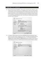
Configuration & Management
RF amplifiers used with wireless LANs are installed in series with the main signal path as
seen below in Figure 5.21. Amplifiers are typically mounted to a solid surface using
screws through the amplifier’s flange plates. Configuration of RF amplifiers is not
generally required unless the amplifier is a variable RF amplifier. If the amplifier is
variable, the amplifier must be configured for the proper amount of amplification
required, according to your RF math calculations. The manufacturer's user manual will
explain how to program or configure the amplifier.
FIGURE 5.21 RF amplifier placement in the wireless LAN system
AmplifierAccess Point
!
Variable amplifiers are not recommended because the settings could inadvertently be
changed, resulting in damage to the antenna or a violation of FCC rules governing
output power in the ISM or UNII bands. Fixed RF amplifiers are recommended, and
the RF calculations should be done ahead of time to make sure the RF signals will be
within FCC guidelines. After the calculations are complete and the necessary amount
of amplification is known, then the RF amplifier should be purchased.
RF Attenuators
An RF attenuator is a device that causes precisely measured loss (in –dB) in an RF signal.
While an amplifier will increase the RF signal, an attenuator will decrease it. Why would
you need or want to decrease your RF signal? Consider the case where an access point
has a fixed output of 100mW, and the only antenna available is an omni-directional
antenna with +20 dBi gain. Using this equipment together would violate FCC rules for
power output, so an attenuator could be added to decrease the RF signal down to 30mW
before it entered the antenna. This configuration would put the power output within FCC
parameters. Figure 5.22 shows examples of fixed-loss RF attenuators with BNC
connectors (left) and SMA connectors (right). Figure 5.23 shows an example of an RF
step attenuator.
CWNA Study Guide © Copyright 2002 Planet3 Wireless, Inc.
Chapter 5 – Antennas and Accessories 126
FIGURE 5.22 A sample of a fixed-loss RF attenuator
FIGURE 5.23 A sample of a RF step attenuator (variable loss)
Common Options
RF attenuators are available as either fixed-loss or variable-loss. Like variable
amplifiers, variable attenuators allow the administrator to configure the amount of loss
that is caused in the RF signal with precision.
!
Variable attenuators are not recommended because the settings could inadvertently be
changed, resulting in damage to the antenna or receiving equipment. Fixed RF
attenuators are recommended where the RF calculations are done ahead of time to
assure the signals are within FCC guidelines. Once the necessary attenuation is
calculated, the appropriate fixed-loss attenuator can be purchased.
FIGURE 5.24 RF Attenuator placement in a wireless LAN
AttenuatorAccess Point
In choosing what kind of attenuator is required, consider the similar items as when
choosing an RF amplifier (see above). The type of attenuator (fixed or variable loss),
impedance, ratings (input power, loss, and frequency response), and connector types
should all be part of the decision-making process.
CWNA Study Guide © Copyright 2002 Planet3 Wireless, Inc.
127 Chapter 5 – Antennas and Accessories
All attenuators should come with a calibration report and certificate, and should be
calibrated once per year thereafter to assure proper operation and continued
performance.
Configuration and Management
Figure 5.24 above shows the proper placement in a wireless LAN for an RF attenuator,
which is directly in series with the main signal path. Fixed, coaxial attenuators are
connected directly between any two connection points between the transmitter and the
antenna. For example, a fixed, coaxial antenna might be connected directly on the output
of an access point, at the input to the antenna, or anywhere between these two points if
multiple RF cables are used. Variable antennas are generally mounted to a surface with
screws through their flange plates or simply placed in a wiring closet on a shelf.
Configuration of RF attenuators is not required unless a variable attenuator is used, in
which case, the amount of attenuation required is configured according to your RF
calculations. Configuration instructions for any particular attenuator will be included in
the manufacturer's user manual.
Lightning Arrestors
A lightning arrestor is used to shunt transient current into the ground that is caused by
lightning. Lightning arrestors are used for protecting wireless LAN hardware such as
access points, bridges, and workgroup bridges that are attached to a coaxial transmission
line. Coaxial transmission lines are susceptible to surges from nearby lightning strikes.
One common misconception about lightning arrestors is that they are installed to
protect against a direct lightning strike. If a bolt of lightning strikes your wireless LAN
antenna with the best lightning arrestor on the market installed, your antenna will be
destroyed and your wireless LAN will probably be damaged as well. A lightning
arrestor is not meant to withstand a direct lightning strike, nor protect your network from
such a strike.
A lightning arrestor can generally shunt (redirect) surges of up to 5000 Amperes at up to
50 Volts. Lightning arrestors function as follows:
1. Lightning strikes a nearby object
2. Transient currents are inducing into the antenna or the RF transmission line
3. The lightning arrestor senses these currents and immediately ionizes the gases
held internally to cause a short (a path of almost no resistance) directly to earth
ground
Figure 5.25 shows how a lightning arrestor is installed on a wireless LAN. When objects
are struck by lightning an electric field is built around that object for just an instant.
When the lightning ceases to induce electricity into the object, the field collapses. When
CWNA Study Guide © Copyright 2002 Planet3 Wireless, Inc.
Chapter 5 – Antennas and Accessories 128
the field collapses, it induces high amounts of current into nearby objects, which, in this
case, would be your wireless LAN antenna or coaxial transmission line.
FIGURE 5.25
A lightning arrestor installed on a network
Lightning
Arrestor
(gas discharge tube)
Access Point
Earth Ground
Common Options
There are few options on a lightning arrestor, and the cost will be between $50 - $150 for
any brand. However, there are some attributes that should be considered for any
lightning arrestor that is purchased:
It should meet the IEEE standard of <8 µS
Reusable
Gas tube breakdown voltage
Connector types
Frequency response
Impedance
Insertion loss
VSWR rating
Warranty
IEEE Standards
Most lightning arrestors are able to trigger a short to Earth ground in under 2
microseconds (µS), but the IEEE specifies that this process should happen in no more
than 8 µS. It is very important that the lightning arrestor you choose at least meet the
IEEE standard.
Reusable
Some lightning arrestors are reusable after a lightning strike and some are not. It is more
cost effective to own an arrestor that can be used a number of times. Reusable models
CWNA Study Guide © Copyright 2002 Planet3 Wireless, Inc.
129 Chapter 5 – Antennas and Accessories
have replaceable gas discharge tube elements that are cheaper to replace than the entire
lightning arrestor. Purchase an arrestor that has a replaceable gas tube and allows for the
arrestor to be left in-line while replacing the gas tube. This feature allows you to replace
the working element of a lightning arrestor without taking the wireless LAN off line for
any length of time.
Voltage Breakdown
Some lightning arrestors support the passing of DC voltage for use in powering RF
amplifiers and others do not. A lightning arrestor should be able to pass the DC voltage
used in powering RF amplifiers if you plan on placing an RF amplifier closer to the
antenna than the lightning arrestor. The gas tube breakdown voltage (the voltage at
which the arrestor begins shorting current to ground) should be higher than the voltage
required to operate in-line RF amplifiers. It is suggested that you place lightning
arrestors as the last component on the RF transmission line before the antenna so that the
lightning arrestor can protect amplifiers and attenuators along with your bridge or access
point.
Connector Types
Make sure the connector types of the lightning arrestor you choose match those on the
cable you are planning to use on your wireless LAN. If they do not match, then adapter
connectors will have to be used, inserting more loss into the RF circuit than is necessary.
Frequency Response
The frequency response specification of the lightning arrestor should be at least as high as
the highest frequency used in a wireless LAN. For example, if you are using only a 2.4
GHz wireless LAN, a lightning arrestor that is specified for use at up to 3 GHz is best.
Impedance
The impedance of the arrestor should match all of the other devices in the circuit between
the transmitter and the antenna. Impedance is usually 50 ohms in most wireless LANs.
Insertion Loss
The insertion loss should be significantly low (perhaps around 0.1 dB) so as not to cause
high RF signal amplitude loss as the signal passes through the arrestor.
VSWR Rating
The VSWR rating of a good quality lightning arrestor will be around 1.1:1, but some may
be as high as 1.5:1. The lower the ratio of the device, the better, since reflected voltage
degrades the main RF signal.
Warranty
Regardless of the quality of a lightning arrestor, the unit can malfunction. Seek out a
manufacturer that offers a good warranty on their lightning arrestors. Some
manufacturers offer a highly desirable "No Matter What" type of warranty.
CWNA Study Guide © Copyright 2002 Planet3 Wireless, Inc.
Chapter 5 – Antennas and Accessories 130
Configuration & Maintenance
No configuration is necessary for a lightning arrestor. Lightning arrestors are installed in
series with the main RF signal path, and the grounding connection should be attached to
an Earth ground with a measurable resistance of 5 ohms or less. It is recommended that
you test an Earth ground connection with an appropriate Earth ground resistance tester
before deciding that the installation of the lightning arrestor is satisfactory. Make it a
point, along with other periodic maintenance tasks, to check the Earth ground resistance
and the gas discharge tube regularly.
RF Splitters
An RF Splitter is a device that has a single input connector and multiple output
connectors. An RF Splitter is used for the purpose of splitting a single signal into
multiple independent RF signals. Use of splitters in everyday implementations of
wireless LANs is not recommended. Sometimes two 120-degree panel antennas or two
90-degree panel antennas may be combined with a splitter and equal-length cables when
the antennas are pointing in opposite directions. This configuration will produce a bi-
directional coverage area, which may be ideal for covering the area along a river or major
highway. Back-to-back 90 degree panels may be separated by as little as 10 inches or as
much as 40 inches on either side of the mast or tower. Each panel in this configuration
may have a mechanical down tilt. The resultant gain in each of the main radiation lobes
is reduced by 3 - 4 dB in these configurations.
When installing an RF splitter, the input connector should always face the source of the
RF signal. The output connectors (sometimes called "taps") are connected facing the
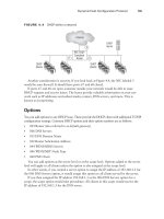
destination of the RF signal (the antenna). Figure 5.26 shows two examples of RF
splitters. Figure 5.27 illustrates how an RF splitter would be used in a wireless LAN
installation.
Splitters may be used to keep track of power output on a wireless LAN link. By hooking
a power meter to one output of the splitter and the RF antenna to the other, an
administrator can actively monitor the output at any given time. In this scenario, the
power meter, the antenna, and the splitter must all have equal impedance. Although not a
common practice, removing the power meter from one output of the splitter and replacing
it with a 50 ohm dummy load would allow the administrator to move the power meter
from one connection point to another throughout the wireless LAN while making output
power measurements.
CWNA Study Guide © Copyright 2002 Planet3 Wireless, Inc.
131 Chapter 5 – Antennas and Accessories
FIGURE 5.26 Sample RF Splitters
FIGURE 5.27 A RF Splitter installed on a network
RF Splitter
Main Signal Path
Choosing an RF Splitter
Below is a checklist of things to consider when choosing an RF splitter.
Insertion loss
Frequency response
Impedance
VSWR rating
High isolation impedance
Power ratings
Connector types
Calibration report
Mounting
DC voltage passing
CWNA Study Guide © Copyright 2002 Planet3 Wireless, Inc.
Chapter 5 – Antennas and Accessories 132
Insertion Loss
Low insertion loss (loss incurred by just introducing the item into the circuit) is necessary
because simply putting the splitter in the RF circuit can cause a significant RF signal
amplitude decrease. Insertion loss of 0.5 dB or less is considered good for an RF splitter.
Do not confuse insertion loss with the loss of amplitude incurred between the input
connector and any output connector (called "through loss"). The number of connectors
on an RF splitter will determine the number of ways (speaking in terms of power
division) that the RF amplitude will be split. A two-way splitter should have a 3 dB loss
between the input connector and either output connector. Loss higher than this can be
attributed either to insertion loss (which is added to through loss when measured) or to
inaccuracies in the splitter's ability to divide the power between output connectors.
Frequency Response
The frequency response specification of the splitter should be at least as high as the
highest frequency used in the wireless LAN. For example, if you are using only a 2.4
GHz wireless LAN, a splitter that is specified for use at up to 3 GHz would be best.
Impedance
The impedance, usually 50 ohms in most wireless LANs, of the splitter should match all
of the other devices in the circuit between the transmitter and the antenna.
VSWR Rating
As with many other RF devices, VSWR ratings should be as close to 1:1 as possible.
Typical VSWR ratings on RF splitters are < 1.5:1. Low VSWR ratings on splitters are
much more critical than on many other devices in an RF system, because reflected RF
power in a splitter may be reflected in multiple directions inside the splitter, affecting
both the splitter input signal and all splitter output signals.
High Isolation Impedance
High isolation impedance between ports on an RF splitter is important for several
reasons. First, a load on one output port should not affect the output power on another
output port of the splitter. Second, a signal arriving into the output port of a splitter (such
as the received RF signal) should be directed to the input port rather than to another
output port. These requirements are accomplished through high impedance between
output connectors. Typical isolation (resistance causing separation) is 20 dB or more
between ports. Some RF splitters have a "feature" known as reverse port isolation that
allows the outputs to be used as inputs. Using the splitter in this way allows the
administrator to connect 2 or 3 access points or bridges to the splitter, which then feeds a
single RF antenna. This configuration can save money on the purchasing and installation
of multiple RF antennas.
CWNA Study Guide © Copyright 2002 Planet3 Wireless, Inc.
133 Chapter 5 – Antennas and Accessories
Power Ratings
Splitters are rated for power input maximums, which means that you are limited in the
amount of power that you can run feed into your splitter. Exceeding the manufacturer's
power rating will result in damage to the RF splitter.
Connector Types
RF splitters will generally have N-type or SMA connectors. It is very important to
purchase a splitter with the same connector types as the cable being used. Doing so cuts
down on adapter connectors, which reduce RF signal amplitude. This knowledge is
especially important when using splitters, since splitters already cut the signal amplitude
in an RF system.
Calibration Report
All RF splitters should come with a calibration report that shows insertion loss, frequency
response, through loss at each connector, etc. Having splitters calibrated once per year is
recommended so that the administrator will know if the splitter is causing any degraded
performance. Calibration requires taking the wireless LAN off line for an extended
period of time, and may not seem practical, but is necessary for continuous optimum
throughput.
Mounting
Mounting an RF splitter is usually a matter of putting screws through the flange plates
into whatever surface on which you the splitter will be mounted. Some models come
with pole-mounting hardware using "U" bolts, mounting plates, and standard-sized nuts.
Depending on the manufacturer, the splitter might be weatherproof, meaning it can be
mounted outside on a pole without fear of water causing problems. When this is the case,
be sure to seal cable connections and use drip loops.
DC Voltage Passing
Some RF splitters have the option of passing the required DC voltage to all output ports
in parallel. This feature is helpful when there are RF amplifiers, which power internal
circuitry with DC voltage originating from a DC voltage injector in a wiring closet,
located on the output of each splitter port.
RF Connectors
RF connectors are specific types of connection devices used to connect cables to devices
or devices to devices. Traditionally, N, F, SMA, BNC, & TNC connectors (or
derivatives) have been used for RF connectors on wireless LANs.
In 1994, the FCC & DOC (Canadian Department of Communications) ruled that
connectors for use with wireless LAN devices should be proprietary between
manufacturers. For this reason, many variations on each connector type exist such as:
N-type
CWNA Study Guide © Copyright 2002 Planet3 Wireless, Inc.
Chapter 5 – Antennas and Accessories 134
Reverse polarity N-type
Reverse threaded N-type
Figure 5.28 illustrates the N and SMA type connectors.
FIGURE 5.28 Sample N-type and SMA connectors
The N Connector The SMA Connector
Choosing an RF Connector
There are five things that should be considered when purchasing and installing any RF
connector, and they are similar in nature to the criteria for choosing RF amplifiers and
attenuators.
1. The RF connector should match the impedance of all other wireless LAN
components (generally 50 ohms).
2. Know how much insertion loss each connector inserted into the signal path
causes. The amount of loss caused will factor into your calculations for signal
strength required and distance allowed.
3. Know the upper frequency limit (frequency response) specified for the particular
connectors. This point will be very important as 5 Ghz wireless LANs become
more and more common. Some connectors are rated only as high as 3 GHz,
which is fine for use with 2.4 GHz wireless LANs, but will not work for 5 GHz
wireless LANs. Some connectors are rated only up to 1 GHz and will not work
with wireless LANs at all, other than legacy 900 MHz wireless LANs.
4. Beware of bad quality connectors. First, always consider purchasing from a
reputable company. Second, purchase only high-quality connectors made by
name-brand manufacturers. This kind of purchasing particularity will help
eliminate many problems with sporadic RF signals, VSWR, and bad connections.
5. Make sure you know both the type of connector (N, F, SMA, etc.) that you need
and the sex of the connector. Connectors come in male and female. Male
connectors have a center pin, and female connectors have a center receptacle.
RF Cables
In the same manner that you must choose the proper cables for your 10 Gbps wired
infrastructure backbone, you must choose the proper cables for connecting an antenna to
CWNA Study Guide © Copyright 2002 Planet3 Wireless, Inc.
135 Chapter 5 – Antennas and Accessories
an access point or wireless bridge. Below are some criteria to be considered in choosing
the proper cables for your wireless network.
Cables introduce loss into a wireless LAN, so make sure the shortest cable length
necessary is used.
Plan to purchase pre-cut lengths of cable with pre-installed connectors. Doing so
minimizes the possibility of bad connections between the connector and the
cable. Professional manufacturing practices are almost always superior to cables
manufactured by untrained individuals.
Look for the lowest loss cable available at your particular price range (the lower
the loss, the more expensive the cable). Cables are typically rated for loss in
dB/100-feet. The table in Figure 5.29 illustrates the loss that is introduced by
adding cables to a wireless LAN.
Purchase cable that has the same impedance as all of your other wireless LAN
components (generally 50 ohms).
The frequency response of the cable should be considered as a primary decision
factor in your purchase. With 2.4 GHz wireless LANs, a cable with a rating of at
least 2.5 GHz should be used. With 5 GHz wireless LANs, a cable with a rating
of at least 6 GHz should be used.
FIGURE 5.29 Coaxial cable attenuation ratings (in dB/foot at X MHz)
LMR CABLE 30 50 150 220 450 900 1500 1800 2000 2500
100A 3.9 5.1 8.9 10.9 15.8 22.8 30.1 33.2 35.2 39.8
195 2.0 2.6 4.4 5.4 7.8 11.1 14.5 16.0 16.9 19.0
200 1.8 2.3 4.0 4.8 7.0 9.9 12.9 14.2 15.0 16.9
240 1.3 1.7 3.0 3.7 5.3 7.6 9.9 10.9 11.5 12.9
300 1.1 1.4 2.4 2.9 4.2 6.1 7.9 8.7 9.2 10.4
400 0.7 0.9 1.5 1.9 2.7 3.9 5.1 5.7 6.0 6.8
400UF 0.8 1.1 1.7 2.2 3.1 4.5 5.9 6.6 6.9 7.8
500 0.54 .70 1.2 1.5 2.2 3.1 4.1 4.6 4.8 5.5
600 0.42 .55 1.0 1.2 1.7 2.5 3.3 3.7 3.9 4.4
600UF 0.48 .63 1.15 1.4 2.0 2.9 3.8 4.3 4.5 5.1
900 0.29 0.37 0.66 0.80 1.17 1.70 2.24 2.48 2.63 2.98
1200 0.21 0.27 0.48 0.59 0.89 1.3 1.7 1.9 2.0 2.3
1700 0.15 0.19 0.35 0.43 0.63 0.94 1.3 1.4 1.5 1.7
There are three major manufacturers of RF cable used with wireless LANs. Those are
Andrew, Times Microwave, and Belden. Andrew's Heliax cable, Times Microwave's
LMR, and Belden's RF-series are all popular in the wireless LAN industry. LMR cable
has become somewhat of an industry standard in the same way Xerox became known
for copiers. Sometimes the term "LMR" is used in place of "RF cable" in the same way
“Xerox” is used in place of “copy.”
CWNA Study Guide © Copyright 2002 Planet3 Wireless, Inc.
Chapter 5 – Antennas and Accessories 136
RF “Pigtail” Adapter Cable
Pigtail adapter cables are used to connect cables that have industry-standard connectors to
manufacturer’s wireless LAN equipment. Pigtails are used to adapt proprietary
connectors to industry standard connectors like N-type and SMA connectors. One end of
the pigtail cable is the proprietary connector while the other end is the industry-standard
connector. Figure 5.30 shows an example of a pigtail cable.
FIGURE 5.30 Sample RF Pigtail adapter
The DOC and FCC (United States Federal Communications Commission) ruling of June
23, 1994, stated that connectors manufactured after June 23, 1994 must be manufactured
as proprietary antenna connectors. The 1994 rule was intended to discourage use of
amplifiers, high-gain antennas, or other means of increasing RF radiation significantly.
The rules are further intended to discourage “home brew” systems which are installed by
inexperienced users and which - either accidentally or intentionally - do not comply with
FCC regulations for use in the ISM band.
Since this rule was enacted, consumers have had to obtain proprietary connectors from
manufacturers to connect to an industry standard connector. Third party manufacturers
have begun custom making these adapter cables (called "pigtails") and selling them
inexpensively on the open market.
CWNA Study Guide © Copyright 2002 Planet3 Wireless, Inc.
137 Chapter 5 – Antennas and Accessories
Key Terms
Before taking the exam, you should be familiar with the following terms:
azimuth
beam
beamwidth
bi-directional amplifier
coverage area
horizontal beamwidth
lobe
narrowing
n-type
pigtails
point-to-multipoint
point-to-point
radiation pattern
SMA-type
transient current
unidirectional amplifier
unused pair
vertical beamwidth
CWNA Study Guide © Copyright 2002 Planet3 Wireless, Inc.
Chapter 5 – Antennas and Accessories 138
Review Questions
1. In a small warehouse installation, you must provide the greatest coverage area
possible for the users inside the warehouse. The warehouse is free from tall
obstructions such as shelving, but has a high ceiling. You have decided to use a
low-gain omni-directional antenna to achieve your goal. For the best coverage area,
where should the antenna be installed?
A. In the center of the building on the roof
B. In the center of the building on the ceiling
C. In one of the corners of the building
D. On one of the walls of the building
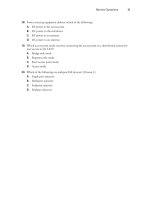
2. When purchasing RF connectors, which of the following should be considered when
making your decision? Choose all that apply.
A. Impedance
B. Insertion loss
C. Gain
D. Maximum frequency allowed
3. You have been hired as a consultant to install a wireless LAN that will connect only
two buildings that are 1.5 miles apart at 11 Mbps. Which one of the following
antennas would you use?
A. Omni-directional
B. High-gain Dipole
C. High-gain Yagi
D. Parabolic dish
4. You have been hired as a consultant to install a wireless LAN that will connect two
buildings that are 10 miles apart. In this particular area, wind gusts are a problem.
Which one of the following antennas would you use?
A. High-gain Grid
B. High-gain Dipole
C. High-gain Yagi
D. Parabolic dish
CWNA Study Guide © Copyright 2002 Planet3 Wireless, Inc.
139 Chapter 5 – Antennas and Accessories
5. You have been hired as a consultant to install a wireless LAN that will connect four
buildings that are 100 meters apart. Which of the following antennas could you use?
Choose all that apply.
A. 4 dipole antennas
B. 4 patch antennas
C. 1 dipole and 3 patch antennas
D. 2 parabolic dish antennas and 2 Yagi antennas
E. 4 panel antennas
6. A wireless LAN installation has a 50-meter cable running between the access point
and a highly-directional antenna. The output signal being sent and received is very
weak at each end of the link. What device should you add to the configuration that
would fix the problem?
A. Uni-directional amplifier
B. Bi-directional amplifier
C. Uni-directional attenuator
D. Bi-directional attenuator
7. The RF signal amplitude loss that occurs because of the natural broadening of the
RF wave front is referred to as which one of the following?
A. Fresnel zone loss
B. Coverage area loss
C. Radiation pattern loss
D. Free space path loss
8. PoE could be used in which one of the following scenarios?
A. To power an antenna that is less than 100 meters away from an access point
B. To power an antenna that is more than 100 meters away from an access point
C. To power an access point that is less than 100 meters away from a wiring
closet
D. To power an access point that is more than 100 meters away from a wiring
closet
9. You are performing an outdoor installation of an omni-directional antenna. Which
of the following will you need to do to ensure proper installation? Choose all that
apply.
A. Check that RF LOS exists with the other antennas in the installation
B. Check that visual LOS exists with the other antennas in the installation
C. Install a lightning arrestor to protect against transient currents
D. Seal all the cable connections in the series to prevent water damage
CWNA Study Guide © Copyright 2002 Planet3 Wireless, Inc.
Chapter 5 – Antennas and Accessories 140
10. Which of the following are true about PoE devices from different manufacturers?
Choose all that apply.
A. They always use the same unused pairs for sending current
B. They are guaranteed to interoperate with devices from other vendors
C. They use the same output voltage
D. They may cause damage to devices from other vendors
11. You have purchased a semi-directional antenna from Vendor A, and an access point
from Vendor B. What type of cables or connectors will you need to complete the
link between the two?
A. An RF cable with industry standard connectors and a pigtail cable with
appropriate connectors
B. An RF cable with connectors matching the access point and a pigtail cable with
appropriate connectors for the antenna and RF cable connection
C. An RF cable with N connectors and a pigtail with N connectors on both sides
D. An RF cable with SMA connectors and a pigtail with N connectors on both
sides
12. An antenna’s beamwidth refers to which one of the following?
A. The width of the RF signal beam that the antenna transmits
B. The width of the antenna main element
C. The width of the mounting beam on which the antenna is mounted
D. The width of the beam of the RF signal relative to the Earth's surface
13. When should an omni-directional antenna be used?
A. When coverage in all horizontal directions from the antenna is required
B. When coverage in a specific direction is required
C. When coverage is required over more than 7 miles in a specific direction
D. Indoors only, for short-range coverage of non-roaming wireless LAN clients
14. Which of the following are names of semi-directional antenna types? Choose all
that apply.
A. Yagi
B. Omni
C. Patch
D. Panel
E. Point-to-point
CWNA Study Guide © Copyright 2002 Planet3 Wireless, Inc.
141 Chapter 5 – Antennas and Accessories
15. The coverage area of a Yagi antenna is ONLY in the direction that the antenna is
pointing. This statement is:
A. Always true
B. Always false
C. Sometimes true, depending on the antenna manufacturer
D. Depends on how the antenna itself is installed
16. Polarization is defined as which one of the following?
A. The direction of the RF antenna in relation to the north and south poles
B. The magnetic force behind the antenna element
C. The power sources of an antenna that cause the antenna to transmit signal in
more than one direction
D. The physical orientation of the antenna in a horizontal or vertical position
17. Which one of the following is an accurate description of an access point with
vertically polarized antennas?
A. Both antennas are standing perpendicular to the Earth's surface
B. Both antennas are standing parallel to the Earth's surface
C. One antenna is parallel to the Earth's surface and the other is perpendicular to
the Earth's surface
18. What is the unit of measurement for gain as related to an RF antenna?
A. Decibels
B. Watts
C. dBi
D. dBm
E. dB
19. Which one of the following defines Free Space Path Loss?
A. The loss incurred by an RF signal whose path has crossed a large free space
B. What occurs as an RF signal is deflected off of its intended path into free space
C. The loss incurred by an RF signal due largely to "signal dispersion" which is a
natural broadening of the wave front
D. The weakening of the RF signal propagation due to an infinite amount of free
space
20. Which of the following are variations of the "N-type" connector?
A. Standard N-type
B. Reverse threaded N-type
C. Reverse polarity N-type
D. Dual head N-type
CWNA Study Guide © Copyright 2002 Planet3 Wireless, Inc.
Chapter 5 – Antennas and Accessories 142
Answers to Review Questions
1. B. In an open area where maximum user coverage is required, using a low-gain
omni antenna makes practical and economic sense. Warehouses typically have high
ceilings, so use of a high-gain omni might not be effective for users below the
antenna. Mounting the antenna near the center of the intended coverage area in an
out-of-the-way place like the ceiling is most effective.
2. A, B, D. Making sure the connector you choose has the right impedance for your
system, has a low insertion loss, and supports frequencies at least as high as the
circuit with which you'll be using it are critical. There is a vast range of quality in
connector choices where seemingly the same connector might cost $1.00 from one
manufacturer and $20.00 from another. Typically, the more expensive manufacturer
has made their connector to exacting standards and fully guarantees their product.
3. C. Yagi antennas are most often used on short to medium length building-to-
building bridging up to 2 miles. Patch and panel antennas are more typically used
on short range building-to-building and in-building directional links and Parabolic
Dish antennas are more often used on very long distance links such as 2-25 miles.
Omni-directional and dipole antennas are the same thing and are mostly used
indoors. If omni antennas are used outdoors, the required coverage area is often
relatively small.
4. A. While both parabolic dish and grid antennas will perform the function of
connecting building miles apart, the grid antenna is designed for maximum
resistance to wind loading by being perforated to let the wind pass through it. A
parabolic dish in this scenario would likely cause intermittent service for the
wireless link due to wind loading.
5. A, C. In this very short-range scenario, 4 omni-directional antennas such as dipoles
could be used. The better scenario for security reasons is to use a single omni-
directional antenna and three semi-directional antennas using only as much power at
each antenna as necessary. This configuration forms a hub-n-spoke topology, which
is commonly used in such point-to-multipoint scenarios.
6. B. By adding a bi-directional amplifier to this scenario, the signal produced by the
access point will be amplified before the antenna transmits the signal. Even though
the received signal is the same amplitude as before, the bi-directional amplifier
boosts the signal before it enters the access point so that the signal is above the
amplitude threshold of the access point.
7. D. Free Space Path Loss or just "Path Loss" is the reason that the amplitude of the
RF signal at the receiver is significantly less than what was transmitted. Path Loss is
a result of both the natural broadening of the wave front and the size of the receiving
aperture.
8. C. Power over Ethernet is used for getting DC power to an access point from a
power injector. Access points located further than 100 meters from a wiring closet
(where the injector will be located) will not have the luxury of PoE because the DC
power is sent over the same cable as the data. Since Cat5 cable can only extend to
100 meters and still be used for reliable data transmission, PoE should not be used
on cable lengths over 100 meters.
CWNA Study Guide © Copyright 2002 Planet3 Wireless, Inc.
143 Chapter 5 – Antennas and Accessories
9. A, C, D. RF line of sight is critical for the proper functioning of any wireless LAN
link. Not having line of sight means that throughput will be reduced, possibly
significantly. Installing lightning arrestors, sealing connectors that are outside the
building, proper grounding, and lightning rods may all be significant parts of an
outdoor installation. Visual line of sight is not necessary in order to have a good RF
connection. Fog, smog, rain, snow, or long distances might for good RF LOS and
no Visual LOS.
10. D. Since no standard yet exists for PoE, manufacturers implement PoE in various
ways. Various voltages and polarities are used as well as different sets of unused
pins in the Cat5 cable. Be careful not to damage your wireless LAN equipment by
using PoE equipment from one vendor and wireless LAN equipment from another.
PoE is sometimes called Power-over-LAN as well.
11. B. A pigtail cable is used to adapt two different kinds of connectors. Typically one
of the connectors is an industry standard type such as an N type or SMA, but not
necessarily. Having the RF cable’s connector match the access point’s connector
saves from having to purchase separate adapter connectors, which would insert more
loss into the circuit. The pigtail cable will be attached to the RF cable and the
antenna.
12. A. Beamwidth refers to the angle of transmission (for both horizontal and vertical)
from an antenna. For example, a patch antenna might have a 45-degree vertical
beamwidth and a 65-degree horizontal beamwidth whereas a dipole antenna might
have a 40-degree vertical beamwidth and would have a 360-degree horizontal
beamwidth.
13. A. Omni-directional antennas radiate in a 360-degree field around the element,
providing complete coverage in the shape of a doughnut horizontally around the
antenna.
14. A, C, D. Yagi, Patch, and Panel antennas are common types of semi-directional
antennas that loosely focus their radiation pattern in general direction.
15. B. Yagi antennas always have a back lobe and sometimes have significant side
lobes as well. The size of these lobes depends on the gain and design of the antenna.
Whether or not the side and rear lobes are used effectively is irrelevant to this
question. The lobes are there regardless of whether or not they are used. Sometimes
these lobes can even interfere with other systems when care is not taken to aim them
properly or to block them with obstacles.
16. D. Since the electric field around the antenna is parallel with the radiating element,
and the electric field defines the polarization, the orientation of the antenna
determines whether the antenna is vertically or horizontally polarized.
17. A. If the access point is sitting on a flat platform and if its antennas are oriented
such that they are vertical (perpendicular to the Earth's surface), then it is vertically
polarized. Both of the diversity antennas commonly found on access points should
be oriented in the same fashion. It is not uncommon to get better reception with
horizontally polarized antennas when using PCMCIA cards in laptop computer. It
all depends on the mounting and positioning of the access point and the relative
location of the laptop computers.
CWNA Study Guide © Copyright 2002 Planet3 Wireless, Inc.
Chapter 5 – Antennas and Accessories 144
18. C. The unit of measure "dBi" means an amount of gain relative to an isotropic
radiator. Isotropic radiators are spheres that radiate RF in all directions
simultaneously such as the sun. We are unable to make such an isotropic radiator,
so any amount of horizontal squeezing of this sphere is considered gain over the
distance that the isotropic radiator would have radiated the signal. Decibels, or
“dB”, are the unit of measure used to measure gain or loss of an RF signal while in a
copper conductor or waveguide.
19. C. When thinking of Path Loss, consider blowing a bubble with chewing gum. As
the bubble gets larger, the amount of gum at any point on the surface gets thinner. If
a one-inch square section of this bubble were taken while the bubble is small, more
gum would be gathered than if the same amount of gum were taken when the bubble
is much larger. This natural broadening of the wavefront thins the amount of power
that a receiver can gather. The one-inch section of gum represents how much power
the receiving aperture (antenna element) can receive.
20. A, B, C. Due to the Canadian Department of Communications and FCC regulations
implemented in 1994, manufacturers had to produce proprietary connectors for their
wireless LAN equipment. Because of this fact, many different variations on
connector types have been created. A good example is the N-type connector. There
are standard, reverse threaded, and reverse polarity N-type connectors on the market
today. There's no such thing as a dual head N-type connector.
CWNA Study Guide © Copyright 2002 Planet3 Wireless, Inc.
CWNA Study Guide © Copyright 2002 Planet3 Wireless, Inc.
Wireless LAN Organizations and
Standards
CWNA Exam Objectives Covered:
Identify, apply, and comprehend the differences between the
following wireless LAN standards:
802.11
802.11b
802.11a
802.11g
Bluetooth
Infrared
HomeRF
Understand the roles of the following organizations in providing
direction and accountability within the wireless LAN industry:
FCC
IEEE
WECA
WLANA
IrDA
ETSI
CHAPTER
5
CHAPTER
6
In This Chapter
FCC
IEEE
Wireless LAN Organizations
Competing Technologies
Chapter 6 – Wireless LAN Organizations and Standards 146
Most computer-related hardware and technologies are based on some standards, and
wireless LANs are no exception. There are organizations that define and support the
standards that allow hardware from different manufacturers to function together
seamlessly. In this chapter we will discuss the FCC’s role in defining and enforcing the
laws governing wireless communication and the IEEE’s role in creating standards that
allow wireless devices to work together. We will also cover the different frequency
bands on which wireless LANs operate, and examine the 802.11 family of standards. We
will discuss some of the major organizations in the wireless LAN marketplace as well as
the roles they fill in the industry. Finally, we will cover some of the emerging
technologies and standards and discuss their impact on the wireless LAN industry.
By understanding the laws and the standards that govern and guide wireless LAN
technology, you will be able to ensure that any wireless system you implement will be
interoperable and comply with the law. Furthermore, familiarity with these statutes and
standards, as well as the organizations that create them, will greatly enhance your ability
to research and find the latest information about wireless LANs.
Federal Communications Commission
The Federal Communications Commission (FCC) is an independent United States
government agency, directly responsible to Congress. The FCC was established by the
Communications Act of 1934 and is charged with regulating interstate and international
communications by radio, television, wire, satellite, and cable. The FCC's jurisdiction
covers not only the 50 states and the District of Columbia, but also all U.S. possessions
such as Puerto Rico, Guam, and The Virgin Islands.
The FCC makes the laws within which wireless LAN devices must operate. The FCC
mandates where on the radio frequency spectrum wireless LANs can operate and at what
power, using which transmission technologies, and how and where various pieces of
wireless LAN hardware may be used.
The website for the FCC is www.fcc.gov
ISM and UNII Bands
The FCC establishes rules limiting which frequencies wireless LANs can use and the
output power on each of those frequency bands. The FCC has specified that wireless
LANs can use the Industrial, Scientific, and Medical (ISM) bands, which are license free.
The ISM bands are located starting at 902 MHz, 2.4 GHz, and 5.8 GHz and vary in width
from about 26 MHz to 150 MHz.
In addition to the ISM bands, the FCC specifies three Unlicensed National Information
Infrastructure (UNII) bands. Each one of these UNII bands is in the 5 GHz range and is
100 MHz wide. Figure 6.1 illustrates the ISM and UNII bands available.
CWNA Study Guide © Copyright 2002 Planet3 Wireless, Inc.
147 Chapter 6 – Wireless LAN Organizations and Standards
FIGURE 6.1 ISM and UNII Spectra
Maritime, Radio Astronomy
F
M
Research, Navigation
Nav,
Astronomy
Nav.
Nav.
10
MHz
100
MHz
1
GHz
10
GHz
900
MHz
910
920 930
FCC:
ISM
902-928MHz
2.4000-2.5000 GHz
2.4000-2.4835 GHz
5.725-5.875 GHz
FCC:
FCC:
ISM
2.400
GHz
2.425
2.450
2.475 2.500
IEEE:
ISM
5.725
GHz
5.775
5.825
5.875
5.000
GHz
5.250
5.500
5.750
6.000
5.725 -
5.825 GHz
5.25 -
5.35 GHz
5.15 -
5.25 GHz
UNII
IEEE & FCC:
Advantages and Disadvantages of License-Free Bands
When implementing any wireless system on a license-free band, there is no requirement
to petition the FCC for bandwidth and power needs. Limits on the power of transmission
exist, but there is no procedure for receiving permission to transmit at such power.
Furthermore, there are no licensing requirements and, thus, no cost associated with
licensing. The license-free nature of the ISM and UNII bands is very important because
it allows entities like small businesses and households to implement wireless systems and
fosters the growth of the wireless LAN market.
Such freedom from licensing carries with it a major disadvantage to license-free band
users. The same license-free band you use (or intend to use) is also license-free to others.
Suppose you install a wireless LAN segment on your home network. If your neighbor
also installs a wireless LAN segment in his home, his system may interfere with yours,
and vise versa. Furthermore, if he uses a higher-power system, his wireless LAN may
disable yours by “whiting out” your wireless traffic. The two competing systems don’t
necessarily have to be on the same channel, or even be the same spread spectrum
technology.
Industrial Scientific Medical (ISM) Bands
There are three license-free ISM bands the FCC has specified that wireless LANs may
use. They are the 900 MHz, 2.4 GHz, and 5.8 GHz bands.
CWNA Study Guide © Copyright 2002 Planet3 Wireless, Inc.
Chapter 6 – Wireless LAN Organizations and Standards 148
900 MHz ISM Band
The 900 MHz ISM band is defined as the range of frequencies from 902 MHz to 928
MHz. This band may be additionally (and correctly) defined as 915 MHz ± 13 MHz.
Though the 900 MHz ISM band was once used by wireless LANs, it has been largely
abandoned in favor of the higher frequency bands, which have wider bandwidths and
allow more throughput. Some of the wireless devices that still use the 900 MHz band are
wireless home phones and wireless camera systems. Organizations that use 900 MHz
wireless LANs find out the hard way that obsolete equipment is expensive to replace
should any piece of their hardware malfunctions. A single 900 MHz radio card may cost
as much as $800 and might only be able to transmit at speeds up to 1 Mbps. In
comparison, an 802.11b compliant wireless card will support speeds up to 11 Mbps and
sell for roughly $100. Finding support or replacements for these older 900 MHz units is
almost impossible.
2.4 GHz ISM Band
This band is used by all 802.11, 802.11b, and 802.11g-compliant devices and is by far the
most populated space of the three bands presented in this chapter. The 2.4 GHz ISM
band is bound by 2.4000 GHz and 2.5000 GHz (2.4500 GHz ± 50 MHz), as defined by
the FCC. Of the 100 MHz between 2.4000 and 2.5000 GHz, only the frequencies 2.4000
– 2.4835 GHz are actually used by wireless LAN devices. The principal reason for this
limitation is that the FCC has specified power output only for this range of frequencies
within the 2.4 GHz ISM band.
5.8 GHz ISM Band
This band is also frequently called the 5 GHz ISM Band. The 5.8 GHz ISM is bound by
5.725 GHz and 5.875 GHz, which yields a 150 MHz bandwidth. This band of
frequencies is not specified for use by wireless LAN devices, so it tends to present some
confusion. The 5.8 GHz ISM band overlaps part of another license-free band, the Upper
UNII band, causing the 5.8 GHz ISM band to be confused with the 5 GHz Upper UNII
band, which is used with wireless LANs.
Unlicensed National Information Infrastructure (UNII) Bands
The 5 GHz UNII bands are made up of three separate 100 MHz-wide bands, which are
used by 802.11a-compliant devices. The three bands are known as the lower, middle, and
upper bands. Within each of these three bands, there are four non-overlapping DSSS
channels, each separated by 5 MHz. The FCC mandates that the lower band be used
indoors, the middle band be used indoors or outdoors, and the upper band be allocated for
outdoor use. Since access points are mostly mounted indoors, the 5 GHz UNII bands
would allow for 8 non-overlapping access points indoors using both the lower and middle
UNII bands.
CWNA Study Guide © Copyright 2002 Planet3 Wireless, Inc.
149 Chapter 6 – Wireless LAN Organizations and Standards
Lower Band
The lower band is bound by 5.15 GHz and 5.25 GHz and is specified by the FCC to have
a maximum output power of 50 mW. When implementing 802.11a compliant devices,
the IEEE has specified 40 mW (80%) as the maximum output power for 802.11a-
compliant radios, reserving the lower band for indoor operation only.
It is important to realize that it is possible for a radio to transmit at 50 mW and operate
within the limits of the law, but still not be compliant with the 802.11a standards. It is
also important to distinguish between what the law allows for and what the standard
specifies. In some rare installation scenarios, you may be required to work outside the
specifications of the standards in order to accomplish a business goal.
Middle Band
The middle UNII band is bound by 5.25 GHz and 5.35 GHz and is specified at 250 mW
of output power by the FCC. The power output specified by IEEE for the middle UNII
band is 200 mW. This power limit allows operation of devices either indoors or outdoors
and is commonly used for short outdoor hops between closely spaced buildings. In the
case of a home installation, such a configuration might include an RF link between the
house and the garage, or the house and a neighbor’s house. Due to reasonable power
output and flexible indoor/outdoor use restrictions, products manufactured to work in the
middle UNII band could enjoy wide acceptance in the future.
Upper Band
The upper UNII band is reserved for outdoor links and is limited by the FCC to 1 Watt
(1000 mW) of output power. This band occupies the range of frequencies between 5.725
GHz and 5.825 GHz, and is often confused with the 5.8 GHz ISM band. The IEEE
specifies the maximum output power for this band as 800 mW, which is plenty of power
for almost any outdoor implementation, except for large campuses or long-distance RF
links.
Power Output Rules
The FCC enforces certain rules regarding the power radiated by the antenna element,
depending on whether the implementation is a point-to-multipoint or a point-to-point
implementation. The term used for the power radiated by the antenna is Equivalent
Isotropically Radiated Power (EIRP).
Point-to-Multipoint (PtMP)
PtMP links have a central point of connection and two or more non-central connection
points. PtMP links are typically configured in a hub-n-spoke topology. The central
connection point may or may not have an omnidirectional antenna (an omnidirectional
antenna produces a 360 degree horizontal beam). It is important to note that when an
omnidirectional antenna is used, the FCC automatically considers the link a PtMP link.
Regarding the setup of a PtMP link, the FCC limits the EIRP to 4 Watts in both the 2.4
CWNA Study Guide © Copyright 2002 Planet3 Wireless, Inc.