ASTM D6371 05 Standard Test Method for Cold Filter Plugging Point of Diesel and Heating Fuels
Bạn đang xem bản rút gọn của tài liệu. Xem và tải ngay bản đầy đủ của tài liệu tại đây (207.18 KB, 8 trang )
Designation: D6371 − 05 (Reapproved 2010)
Standard Test Method for
Cold Filter Plugging Point of Diesel and Heating Fuels
1
This standard is issued under the fixed designation D6371; the number immediately following the designation indicates the year of
original adoption or, in the case of revision, the year of last revision. A number in parentheses indicates the year of last reapproval. A
superscript epsilon (´) indicates an editorial change since the last revision or reapproval.
1. Scope
1.1 This test method covers the determination of the cold
filter plugging point (CFPP) temperature of diesel and domes-
tic heating fuels using either manual or automated apparatus.
NOTE 1—This test method is technically equivalent to test methods
IP 309 and EN 116.
1.2 The manual apparatus and automated apparatus are both
suitable for referee purposes.
1.3 This test method is applicable to distillate fuels, includ-
ing those containing a flow-improving or other additive,
intended for use in diesel engines and domestic heating
installations.
1.4 The values stated in SI units are to be regarded as
standard. No other units of measurement are included in this
standard.
1.5 WARNING—Mercury has been designated by many
regulatory agencies as a hazardous material that can cause
central nervous system, kidney and liver damage. Mercury, or
its vapor, may be hazardous to health and corrosive to
materials. Caution should be taken when handling mercury and
mercury containing products. See the applicable product Ma-
terial Safety Data Sheet (MSDS) for details and EPA’s
website— addi-
tional information. Users should be aware that selling mercury
and/or mercury containing products into your state or country
may be prohibited by law.
1.6 This standard does not purport to address all of the
safety concerns, if any, associated with its use. It is the
responsibility of the user of this standard to establish appro-
priate safety and health practices and determine the applica-
bility of regulatory limitations prior to use. For specific
warning statements, see Section
7.
2. Referenced Documents
2.1 ASTM Standards:
2
D2500 Test Method for Cloud Point of Petroleum Products
D4057 Practice for Manual Sampling of Petroleum and
Petroleum Products
D4177 Practice for Automatic Sampling of Petroleum and
Petroleum Products
D5771 Test Method for Cloud Point of Petroleum Products
(Optical Detection Stepped Cooling Method)
D5772 Test Method for Cloud Point of Petroleum Products
(Linear Cooling Rate Method)
D5773 Test Method for Cloud Point of Petroleum Products
(Constant Cooling Rate Method)
E1 Specification for ASTM Liquid-in-Glass Thermometers
2.2 IP Standards:
3
IP 309 Diesel and domestic heating fuels - Determination of
cold filter plugging point
Specifications for IP Standard Thermometers
2.3 ISO Standards:
4
IP 3310 Test sieves - Technical requirements and testing -
Part 1: Metal cloth
2.4 European Standards:
5
EN 116 Diesel and domestic heating fuels - Determination
of cold filter plugging point
3. Terminology
3.1 Definitions of Terms Specific to This Standard:
1
This test method is under the jurisdiction of ASTM Committee D02 on
Petroleum Products and Lubricantsand is the direct responsibility of Subcommittee
D02.07 on Flow Properties.
Current edition approved Aug. 1, 2010. Published November 2010. Originally
approved in 1999. Last previous edition approved in 2005 as D6371–05. DOI:
10.1520/D6371-05R10.
2
For referenced ASTM standards, visit the ASTM website, www.astm.org, or
contact ASTM Customer Service at For Annual Book of ASTM
Standards volume information, refer to the standard’s Document Summary page on
the ASTM website.
3
Available from Energy Institute, 61 New Cavendish St., London, WIG 7AR,
U.K., .
4
Available from American National Standards Institute (ANSI), 25 W. 43rd St.,
4th Floor, New York, NY 10036, .
5
Available from European Committee for Standardization (CEN), 36 rue de
Stassart, B-1050, Brussels, Belgium, .
Copyright © ASTM International, 100 Barr Harbor Drive, PO Box C700, West Conshohocken, PA 19428-2959. United States
1
Copyright by ASTM Int'l (all rights reserved); Sat Oct 19 11:52:32 EDT 2013
Downloaded/printed by
Pontifcia Universidade Catlica do Rio Grande do Sul pursuant to License Agreement. No further reproductions authorized.
3.1.1 certified reference material, n—a stable petroleum
product with a method-specific nominal CFPP value estab-
lished by a method-specific interlaboratory study following
RR:D02-1007
6
guidelines or ISO Guides 34 and 35.
4
3.1.2 cold filter plugging point, n—highest temperature,
expressed in multiples of 1°C, at which a given volume of fuel
fails to pass through a standardized filtration device in a
specified time when cooled under the conditions prescribed in
this test method.
4. Summary of Test Method
4.1 A specimen of the sample is cooled under specified
conditions and, at intervals of 1°C, is drawn into a pipet under
a controlled vacuum through a standardized wire mesh filter.
The procedure is repeated, as the specimen continues to cool,
for each 1°C below the first test temperature. Testing is
continued until the amount of wax crystals that have separated
out of solution is sufficient to stop or slow down the flow so
that the time taken to fill the pipet exceeds 60 s or the fuel fails
to return completely to the test jar before the fuel has cooled by
a further 1°C.
4.2 The indicated temperature at which the last filtration
was commenced is recorded as the CFPP.
5. Significance and Use
5.1 The CFPP of a fuel is suitable for estimating the lowest
temperature at which a fuel will give trouble-free flow in
certain fuel systems.
5.2 In the case of diesel fuel used in European light duty
trucks, the results are usually close to the temperature of failure
in service except when the fuel system contains, for example,
a paper filter installed in a location exposed to the weather or
if the filter plugging temperature is more than 12°C below the
cloud point value in accordance with Test Method
D2500,
D5771, D5772,orD5773. Domestic heating installations are
usually less critical and often operate satisfactorily at tempera-
tures somewhat lower than those indicated by the test results.
5.3 The difference in results obtained from the sample as
received and after heat treatment at 45°C for 30 min can be
used to investigate complaints of unsatisfactory performance
under low temperature conditions.
6. Apparatus
6.1 Manual Apparatus:
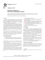
6.1.1 The apparatus, as detailed in
6.1.2-6.1.13, shall be
arranged as shown in
Fig. 1.
6.1.2 Test Jar, cylindrical, of clear glass, flat bottomed, with
an internal diameter of 31.5 6 0.5 mm, a wall thickness of 1.25
60.25 mm and a height of 120 6 5 mm. The jar shall have a
permanent mark at the 45 6 1 mL level.
NOTE 2—Test jars of the required dimensions may be obtained by
selection from jars conforming to Test Method
D2500, which specifies a
wider diameter tolerance.
6.1.3 Jacket, brass, watertight, cylindrical, flat bottomed, to
be used as an air bath. It shall have an inside diameter of 45 6
0.25 mm, outside diameter of 48 6 0.25 mm, and a height of
115 6 3 mm (see
Fig. 2).
6.1.4 Insulating Ring, made from oil-resistant plastics or
other suitable material, to be placed in the bottom of the jacket
(see
6.1.3) to provide insulation for the bottom of the test jar.
It shall fit closely inside the jacket and have a thickness of 6 +
0.3 - 0.0 mm.
6.1.5 Spacers (two) , approximately 5-mm thick, made of
oil-resistant plastics or other suitable material, to be placed as
shown in
Fig. 1 around the test jar (see 6.1.2) to provide
insulation for the test jar from the sides of the jacket. The
spacers shall fit closely to the test jar and closely inside the
jacket. The use of incomplete rings, each with a 2-mm
circumferential gap, will accommodate variations in test jar
diameter. The spacers and insulating ring may be made as a
single part as shown in
Fig. 3.
6.1.6 Supporting Ring, of oil resistant plastics or other
suitable non-metallic, non-absorbent, oil-resistant material,
used to suspend the jacket (see
6.1.3) in a stable and upright
position in the cooling bath and to provide a concentric
location for the stopper (see
6.1.7). A design is shown in Fig.
4
for guidance, but this design may be modified to suit the
cooling bath.
6.1.7 Stopper, of oil-resistant plastics or other suitable
nonmetallic, nonabsorbent, oil-resistant material, to fit the test
jar and the support ring as shown in
Fig. 5. It shall have three
holes to accommodate the pipet (see 6.1.8) and the thermom-
eter (see
6.1.9) and to allow venting of the system. If necessary,
when using the high-range thermometer (see
6.1.9), the upper
part of the stopper shall have an indentation to permit the
thermometer (see
6.1.9) to be read down to a temperature of
6
Supporting data have been filed at ASTM International Headquarters and may
be obtained by requesting Research Report RR:D02-1007.
NOTE 1—All dimensions are in millimetres, and the comma (,) is used
as the decimal point.
FIG. 1 Arrangement of Manual CFPP Apparatus
D6371 − 05 (2010)
2
Copyright by ASTM Int'l (all rights reserved); Sat Oct 19 11:52:32 EDT 2013
Downloaded/printed by
Pontifcia Universidade Catlica do Rio Grande do Sul pursuant to License Agreement. No further reproductions authorized.
-30°C. A pointer shall be fitted to the upper surface of the
stopper to facilitate location of the thermometer in relation to
the bottom of the test jar. A spring wire clip shall be used to
retain the thermometer in the correct position.
6.1.8 Pipet with Filter Unit:
6.1.8.1 Pipet, of clear glass with a calibration mark corre-
sponding to a contained volume of 20 6 0.2 mL at a point 149
6 0.5 mm from the bottom of the pipet (see
Fig. 6). It shall be
connected to the filter unit (see 6.1.8.2).
6.1.8.2 Filter Unit (see Fig. 7), containing the following
elements:
NOTE 1—All dimensions are in millimetres, and the comma (,) is used
as the decimal point.
FIG. 2 Watertight Brass Jacket
NOTE 1—All dimensions are in millimetres, and the comma (,) is used
as the decimal point.
FIG. 3 Spacers
NOTE 1—All dimensions are in millimetres, and the comma (,) is used
as the decimal point.
FIG. 4 Supporting Ring
NOTE 1—All dimensions are in millimetres, and the comma (,) is used
as the decimal point.
FIG. 5 Stopper with Holes for Thermometer, Pipet, and Vent
D6371 − 05 (2010)
3
Copyright by ASTM Int'l (all rights reserved); Sat Oct 19 11:52:32 EDT 2013
Downloaded/printed by
Pontifcia Universidade Catlica do Rio Grande do Sul pursuant to License Agreement. No further reproductions authorized.
(1) Brass Body, with a threaded cavity that houses the wire
mesh holder. The cavity shall be fitted with an O-ring of
oil-resistant plastics. The internal diameter of the central tube
shall be 4 6 0.1 mm.
(2) Brass Screw Cap, to connect the upper part of the body
of the filter unit (see
6.1.8.2) to the lower part of the pipet (see
6.1.8.1) to ensure a leak-free joint. An example of satisfactory
connection is shown in
Fig. 7.
(3) Disc,156 0.1-mm diameter, of plain weave stainless
steel wire mesh gauze with a nominal aperture size of 45 µm.
The nominal diameter of the wire shall be 32 µm, and the
tolerance for the size of an individual aperture shall be as
follows:
No aperture size shall exceed the nominal size by more
than 22 µm.
The average aperture size shall be within 6 3.1 µm of the
nominal size.
Not more than 6 % of the apertures shall be above the
nominal size by more than 13 µm.
(4) Filter Holder of Brass, in which the disc of wire mesh
gauze (see
6.1.8.2 (3)) is firmly clamped by a retaining ring
pressed into the filter holder. The diameter of the exposed part
of the gauze shall be 12 + 0.1 - 0.0 mm (see
Fig. 8).
(5) Brass Cylinder, threaded on the outside, that can be
screwed into the cavity of the body (see
6.1.8.2 (1)) to clamp
the filter holder (see
6.1.8.2 (4)) against the O-ring (6.1.8.2
(1)), The lower end shall have four slots to allow the specimen
to flow into the filter unit.
NOTE 3—The requirements for the wire mesh are taken from
IP 3310
IP 3310, to which reference may be made for methods for testing
the gauze.
6.1.9 Thermometers, having ranges shown below and con-
forming to the requirements prescribed in Specification
E1 or
Specifications for IP Standard Thermometers.
NOTE 1—All dimensions are in millimetres, and the comma (,) is used
as the decimal point.
FIG. 6 Pipet
NOTE 1—All dimensions are in millimetres, and the comma (,) is used
as the decimal point.
FIG. 7 Filter Unit
NOTE 1—All dimensions are in millimetres, and the comma (,) is used
as the decimal point.
FIG. 8 Brass Filter Holder
D6371 − 05 (2010)
4
Copyright by ASTM Int'l (all rights reserved); Sat Oct 19 11:52:32 EDT 2013
Downloaded/printed by
Pontifcia Universidade Catlica do Rio Grande do Sul pursuant to License Agreement. No further reproductions authorized.
Thermometer Number
Thermometer Temperature Range ASTM IP
High-range for CFPP down to
−30°C
−38°C to +50°C 5C 1C
Low-range from CFPP below
−30°C
–80°C to +20°C 6C 2C
Cooling bath −80°C to +20°C 6C 2C
6.1.10 Cooling Bath:
6.1.10.1 The type of cooling bath is optional, but it shall be
of a shape and size suitable for containing the jacket (see
6.1.3)
in a stable and upright position at the required depth.
6.1.10.2 The bath shall be fitted with a cover with one or
more holes in it to accommodate the supporting ring (see
6.1.6). The jacket (see 6.1.3) may be permanently mounted in
the cover.
6.1.10.3 The bath temperature shall be maintained at the
required value and tolerance by a refrigeration unit or by the
use of suitable freezing mixtures, ensuring a homogenous
temperature in the bath by stirring or other means of agitation.
Table 1 lists the bath temperature set-points required in the
CFPP procedure. If only one bath is utilized, it must have the
ability to change down to the next lower set-point temperature
in a time period not exceeding 2 min 30 s.
6.1.11 Stopcock, glass, with double oblique bore of 3-mm
diameter.
6.1.12 Vacuum Source, vacuum pump or water pump pow-
erful enough to ensure an air flow rate in the vacuum regulator
of 15 6 1 L/h for the duration of the test.
6.1.13 Vacuum Regulator, consisting of a glass bottle, at
least 350-mm high, not less than 5 L capacity, partially filled
with water. It shall be closed by a stopper with three holes of
convenient diameters for glass tubes. Two tubes shall be short
and shall not go below the water level. The third tube, with an
internal diameter of 10 6 1 mm, shall be long enough for one
end to be approximately 200 mm beneath the surface of the
water while the other end reaches a few centimetres above the
stopper. The depth of the immersed part shall then be adjusted
to obtain a depression of 200 6 1 mm of water (2 6 0.05 kPa)
on the manometer, which shall contain water. A second empty
5 L bottle shall be fitted in the line to serve as a vacuum
reservoir to ensure a constant depression. The arrangement is
shown in
Fig. 1.
6.1.14 Stopwatch, with a graduation or reading of 0.2 s or
lower, with an accuracy of 0.1 % over a period of 10 min.
6.2 Automated Apparatus:
6.2.1 The automated apparatus shall include elements con-
forming to
6.1.1-6.1.8, platinum resistance thermometers,
cooling bath(s), vacuum pump, and suitable electronic control
and measurement devices.
6.2.2 Cooling Bath, a refrigeration unit capable of maintain-
ing the cooling bath at the required temperature and also of
automatically changing the bath temperature within 2 min 30 s
at the appropriate stage (see
12.2.5).
6.2.3 Vacuum Pump, powerful enough to ensure an air flow
rate in the vacuum regulator of a minimum of 15 6 1 L/h, and
to maintain a constant vacuum of 200 6 1mm(26 0.05 kPa)
for the duration of the test. For multi-position testers using the
same vacuum pump, the flow rate shall be checked when
several positions are operating simultaneously.
7. Reagents and Materials
7.1 Heptane, clean commercial or reagent grade.
(Warning—Flammable. Harmful if inhaled.)
7.2 Acetone, clean commercial or reagent grade.
(Warning—Extremely flammable.)
7.3 Filter Paper, (approximately 4 to 6 µm retention).
7.4 Certified Reference Materials.
8. Sampling
8.1 Unless otherwise specified in the commodity specifica-
tion, samples shall be taken as described in Practice
D4057 or
D4177 in accordance with the requirements of national stan-
dards or regulation for the sampling of the product under test,
or both.
9. Preparation of Test Specimen
9.1 Filter approximately 50 mL of the sample (see
8.1)at
laboratory ambient temperature, but in any case not at a
temperature less than 15°C, through dry filter paper (see
7.3).
10. Preparation of Apparatus
10.1 Prepare the manual apparatus or the automated appa-
ratus for operation in accordance with the manufacturer’s
instructions for calibrating, checking, and operating the equip-
ment. See
Fig. 1 for manual apparatus.
10.2 Before each test, dismantle the filter unit (see
6.1.8.2)
and wash the pieces and the test jar (see 6.1.2), the pipet (see
6.1.8.1) and the thermometer (see 6.1.9 for manual apparatus
and
6.2 for platinum resistance used in automated equipment)
with heptane (see 7.1), then rinse with acetone (see 7.2) and
dry in a stream of filtered air. Check the cleanliness and
dryness of all elements, including the jacket (see
6.1.3).
Examine the wire mesh (see
6.1.8.2(3)) and the joints (see
6.1.8.2(1) and 6.1.8.2(2) for damage; if necessary renew them.
10.3 Check that the screw cap (see
6.1.8.2(2)) is tight
enough to prevent leakage.
11. Calibration and Standardization
11.1 Adjust the automated CFPP apparatus (when used) in
accordance with the manufacturer’s instructions.
11.2 Calibrate the temperature measuring device in accor-
dance with the manufacturer’s instructions.
11.3 Periodically verify the correct functioning of manual
and automated apparatus using a certified reference material or
in-house secondary reference material, such as fuel of known
CFPP value.
NOTE 4—It is preferable that verification be carried out at least two
times a year, where possible, using certified reference materials. The
TABLE 1 Cooling Bath Temperatures
Expected CFPP Required Cooling Bath Temperature(s)
Down to −20°C −34 ± 0.5°C
Between −20°C and −35°C −34 ± 0.5°C then −51 ± 1°C
Below −35°C −34 ± 0.5°C then –51 ± 1°C then −67 ± 2°C
D6371 − 05 (2010)
5
Copyright by ASTM Int'l (all rights reserved); Sat Oct 19 11:52:32 EDT 2013
Downloaded/printed by
Pontifcia Universidade Catlica do Rio Grande do Sul pursuant to License Agreement. No further reproductions authorized.
apparatus should be checked more frequently (for example, weekly) using
a secondary verification material.
11.4 When the CFPP values obtained using a verification
material deviate by more than the test repeatability (see 15.2),
or an unacceptable statistical quality control bias is observed,
check the condition and operation of the apparatus to ensure
conformity with the specification as stated in this test method.
The manufacturer’s instruction manual should provide guid-
ance on ensuring that the apparatus is correctly set up and
calibrated.
12. Procedure
12.1 Manual Apparatus:
12.1.1 Establish the cooling bath temperature at –34 6
0.5°C.
12.1.2 Place the insulating ring (see
6.1.4) on the bottom of
the jacket (see 6.1.3). If spacers (see 6.1.5) are not mounted on
the insulating ring (see
6.1.4), position them approximately 15
and 75 mm above the bottom of the test jar (see 6.1.2).
12.1.3 Pour the filtered specimen (see Section
9) into the
clean and dry test jar to the mark (45 mL).
12.1.4 Close the test jar with the stopper (see
6.1.7) carrying
the pipet with filter unit (see 6.1.8) and the appropriate
thermometer (see
6.1.9). Use a low-range thermometer if the
expected CFPP is below –30°C. Thermometers shall not be
changed during the test. Adjust the apparatus in such a way that
the bottom of the filter unit (see
6.1.8.2(5)) rests on the bottom
of the test jar, and position the thermometer so that its lower
end is 1.5 6 0.2 mm above the bottom of the test jar. Take care
to ensure that no part of the thermometer is not in contact with
the side of the test jar or the filter body.
NOTE 5—The precise positioning of the thermometer in the test jar is a
critical parameter of this test method. The position of the lower end of the
thermometer above the bottom of the test jar can be indirectly measured
by marking the stem of the thermometer flush with the stopper (see
6.1.7)
when the lower end of the thermometer is just touching the bottom of the
test jar, and then pulling the thermometer up such that the reference line
is 1.5 6 0.2 mm above the top of the stopper.
12.1.5 If the jacket is not an integral part of the cooling bath,
place the jacket vertically to a depth of 85 6 2mminthe
cooling bath (see
6.1.10), which is maintained at the tempera-
ture of –34 6 0.5°C.
12.1.6 Insert the test jar assembly in a stable vertical
position into the jacket.
12.1.7 With the stopcock (see
6.1.11) open to atmosphere,
connect the pipet to the vacuum system (see
6.1.12 and 6.1.13)
by means of flexible tubing attached to the stopcock (see
Fig.
1). Switch on the vacuum source and regulate to ensure an air
flow rate of 15 L/h in the vacuum regulator (see
6.1.13). Before
starting a test, check that the U-tube manometer indicates a 200
6 1 mm of water depression (2 6 0.05 kPa).
12.1.8 Start the test immediately after inserting the test jar
assembly into the jacket, but if the cloud point of the sample is
known, it is permitted to wait until the specimen has cooled to
a temperature of not less than 5°C above its cloud point.
12.1.9 When the specimen temperature reaches a suitable
integer value, turn the stopcock (see
6.1.11) so that the filter
assembly is connected to the vacuum source, causing the
specimen to be drawn through the wire mesh into the pipet;
simultaneously start the stopwatch.
12.1.10 When the specimen reaches the mark on the pipet,
stop the stopwatch and turn the stopcock to its initial position
to vent the pipet and so allow the specimen to return to the test
jar.
12.1.11 If the time taken to reach the mark exceeds 60 s on
the first filtration, abandon the test and repeat it on a fresh
portion, starting at a higher temperature.
12.1.12 Repeat the operations (see
12.1.9 to 12.1.10) for
each 1°C decrease of the specimen temperature until the
temperature is reached at which the pipet is not filled to the 20
mL mark within 60 s. Record the temperature at which this last
filtration was commenced as CFPP (see Section
13).
NOTE 6—A small minority of samples may exhibit anomalous aspira-
tion behavior, which can be detected by examining the observed aspiration
times. This behavior is marked by an unexpected reduction in the time
taken to fill the pipet, after which aspiration time again continues to
increase progressively, until the failure limit of 60 s is reached.
12.1.13 If the filter has not plugged when the temperature of
the specimen reaches –20°C, continue the test by using a
second cooling bath maintained at –51 6 1°C, quickly trans-
ferring the test jar and filtration assembly to a new jacket
placed on the second cooling bath. Alternatively, for single
bath apparatus, adjust the refrigeration unit to –51 6 1°C. The
new temperature must be reached within 2 min 30 s of the
adjustment. Repeat the operations
12.1.9 to 12.1.10 to each
1°C decrease of the specimen temperature.
12.1.14 If the filter has not plugged when the temperature of
the specimen reaches –35°C, continue the test by using a third
cooling bath maintained at –67 6 2°C by quickly transferring
the test jar and filtration assembly to a new jacket placed on the
second cooling bath. Alternatively, for single bath apparatus,
adjust the refrigeration unit to –67 6 2°C. The new tempera-
ture must be reached within 2 min 30 s of the adjustment.
Repeat the operations
12.1.9 to 12.1.10 at each 1°C decrease of
the specimen temperature.
12.1.15 If the filter has not plugged when the temperature of
the specimen reaches –51°C, discontinue the test (see Section
13).
12.1.16 If, after cooling in accordance with
12.1.12,
12.1.13, and 12.1.14, the specimen fills the pipet to the mark in
less than 60 s, but does not flow back completely into the test
jar when the pipet is vented to atmosphere through the
stopcock (see
6.1.11) before the start of the next aspiration,
record the temperature at the commencement of the filtration as
the CFPP (see Section 13).
12.2 Automated Apparatus:
12.2.1 Check that the cooling bath is operating and has
reached the temperature required as specified in the manufac-
turer’s instructions.
12.2.2 Pour the filtered specimen (see Section
9) into the
clean and dry test jar to the 45 mL mark.
12.2.3 Close the test jar with the stopper (see
6.1.7) carrying
the pipet with filter unit (see
6.1.8) and the platinum resistance
thermometer. Adjust the apparatus in such a way that the
bottom of the filter unit (see
6.1.8.2(5)) rests on the bottom of
the test jar, and position the thermometer so that its lower end
D6371 − 05 (2010)
6
Copyright by ASTM Int'l (all rights reserved); Sat Oct 19 11:52:32 EDT 2013
Downloaded/printed by
Pontifcia Universidade Catlica do Rio Grande do Sul pursuant to License Agreement. No further reproductions authorized.
is 1.5 6 0.2 mm above the bottom of the test jar. Take care to
ensure that no part of the thermometer is in contact with the
side of the test jar or the filter body.
NOTE 7—The precise positioning of the thermometer in the test jar is a
critical parameter of this test method. The position of the lower end of the
thermometer above the bottom of the test jar can be indirectly measured
by marking the stem of the thermometer flush with the stopper (see
6.1.7)
when the lower end of the thermometer is just touching the bottom of the
test jar, and then pulling the thermometer up such that the reference line
is 1.5 6 0.2 mm above the top of the stopper.
12.2.4 If necessary, reconnect the pipet to the vacuum
system. Switch on the vacuum source and regulate to ensure an
air flow rate of 15 L/h in the vacuum regulator. Check that the
U-tube manometer (if used) indicates a 200 6 1 mm depres-
sion (2 6 0.05 kPa) or that the electronic vacuum regulator
indicates a pressure of 2 6 0.05 kPa.
12.2.5 Press the start button immediately after insertion of
the test jar assembly. If the cloud point is known, aspiration of
the specimen through the filter may be set to start when it has
cooled to a temperature not less than 5°C above the cloud
point. The apparatus will carry out the test procedure filtering
the specimen at each 1°C decrease if temperature and measur-
ing the filtering time. If the time to reach the 20 mL mark
exceeds 60 s on the first filtration, the test is to be abandoned
and repeated on a fresh specimen starting at a higher tempera-
ture. The apparatus will record the first temperature at which
the specimen fails to reach the 20 mL mark in less than 60 s or
fails to flow back into the test jar when the vacuum is cut off
as CFPP (see Section
13). The test will be discontinued if the
specimen reaches −51°C without plugging (see Section
13).
During the procedure, the apparatus will automatically change
the cooling bath temperature as indicated below.
Bath Temperature
Start of test −34 ± 0.5°C
When (if) specimen reaches −20°C −51 ± 1°C
When (if) specimen reaches −35°C −67 ± 2°C
NOTE 8—A small minority of samples may exhibit anomalous aspira-
tion behavior, which can be detected by examining the aspiration times
recorded in the test printout for signs of an unexpected reduction in the
time taken to fill the pipet, after which aspiration time again continues to
increase progressively until the failure limit of 60 s is reached.
12.2.6 If the automated CFPP apparatus used does not
incorporate a lower light sensor, it shall only be used if the test
sequence is observed as in the manual procedure (see
12.1.16),
so that any fuels not flowing back into the test jar as described
are detected and reported accordingly.
13. Report
13.1 Report the temperature read or indicated at the begin-
ning of the last filtration to the nearest 1°C (see
12.1.12,
12.1.16, and 12.2.5) as the CFPP.
13.2 If the specimen has reached −51°C without plugging
(see
12.1.15 and 12.2.5) report as “Not plugged at −51°C.”
13.3 The report shall contain at least the following informa-
tion:
13.3.1 The type and identification of the product under test;
13.3.2 A reference to this test method;
13.3.3 The sampling procedure used (see Section
8);
13.3.4 The result of the test (
13.1 or 13.2);
13.3.5 Any deviation from the procedure described (see
Note 6 and Note 8); and
13.3.6 the date of the test.
14. Precision and Bias
14.1 The precision of this procedure as determined by the
statistical examination of the interlaboratory test results is as
follows:
14.2 Repeatability—The difference between results ob-
tained on the same day by the same operator with the same
apparatus under constant operating conditions on identical test
material, would in the long run, with normal and correct
operation of the test method, exceed 1.76°C only in one case in
twenty.
14.3 Reproducibility—The difference between two single
and independent results obtained by different operators work-
ing in different laboratories on identical test material, would in
the long run, in the normal and correct operation of the test
method, exceed the values indicated by the formula:
0.102 (25−X)°C
where: X is the average of the two results being compared,
only in one case in twenty.
NOTE 9—The interlaboratory test program used to determine the
precision of this test method was carried out in 1988 by the IP. The
program involved 46 laboratories and 5 samples, ranging in CFPP values
from 0°C to −33°C. Extrapolations to measurements more than a few
degrees outside this range are unsupported by the data. The raw data from
the 1988 program was reanalyzed in 1997 using the ASTM D2PP
program. The report of the reevaluation is available from ASTM Head-
quarters.
7
14.4 Bias—The procedure in this test method has no bias
because the value of CFPP can be defined only in terms of a
test method.
14.5 Relative Bias—The current interlaboratory tests con-
firm that there is no relative bias between the manual and
automated apparatuses. Both apparatuses are suitable for ref-
erence purposes.
15. Keywords
15.1 automated cold filter plugging point; cold filter plug-
ging point (CFPP); diesel; domestic heating fuels; filterability;
manual cold filter plugging point
7
Supporting data have been filed at ASTM International Headquarters and may
be obtained by requesting Research Report RR:D02-1452.
D6371 − 05 (2010)
7
Copyright by ASTM Int'l (all rights reserved); Sat Oct 19 11:52:32 EDT 2013
Downloaded/printed by
Pontifcia Universidade Catlica do Rio Grande do Sul pursuant to License Agreement. No further reproductions authorized.
ASTM International takes no position respecting the validity of any patent rights asserted in connection with any item mentioned
in this standard. Users of this standard are expressly advised that determination of the validity of any such patent rights, and the risk
of infringement of such rights, are entirely their own responsibility.
This standard is subject to revision at any time by the responsible technical committee and must be reviewed every five years and
if not revised, either reapproved or withdrawn. Your comments are invited either for revision of this standard or for additional standards
and should be addressed to ASTM International Headquarters. Your comments will receive careful consideration at a meeting of the
responsible technical committee, which you may attend. If you feel that your comments have not received a fair hearing you should
make your views known to the ASTM Committee on Standards, at the address shown below.
This standard is copyrighted by ASTM International, 100 Barr Harbor Drive, PO Box C700, West Conshohocken, PA 19428-2959,
United States. Individual reprints (single or multiple copies) of this standard may be obtained by contacting ASTM at the above
address or at 610-832-9585 (phone), 610-832-9555 (fax), or (e-mail); or through the ASTM website
(www.astm.org). Permission rights to photocopy the standard may also be secured from the ASTM website (www.astm.org/
COPYRIGHT/).
D6371 − 05 (2010)
8
Copyright by ASTM Int'l (all rights reserved); Sat Oct 19 11:52:32 EDT 2013
Downloaded/printed by
Pontifcia Universidade Catlica do Rio Grande do Sul pursuant to License Agreement. No further reproductions authorized.