aisc design guide 10 - erection bracing of low-rise structural steel buildings
Bạn đang xem bản rút gọn của tài liệu. Xem và tải ngay bản đầy đủ của tài liệu tại đây (1.14 MB, 83 trang )
Steel Design Guide Series
Erection Bracing
of Low-Rise Structural Steel Buildings
Steel Design Guide Series
Erection Bracing
of Low-Rise Structured Steel Buildings
James M. Fisher, PhD, P. E.
and Michael A. West, P. E.
Computerized Structural Design
Milwaukee, Wisconsin
AMERICAN INSTITUTE OF STEEL CONSTRUCTION
© 2003 by American Institute of Steel Construction, Inc. All rights reserved.
This publication or any part thereof must not be reproduced in any form without permission of the publisher.
Copyright 1997
by
American Institute of Steel Construction, Inc.
All rights reserved. This book or any part thereof
must not be reproduced in any form without the
written permission of the publisher.
The information presented in this publication has been prepared in accordance with rec-
ognized engineering principles and is for general information only. While it is believed
to be accurate, this information should not be used or relied upon for any specific appli-
cation without competent professional examination and verification of its accuracy,
suitablility, and applicability by a licensed professional engineer, designer, or architect.
The publication of the material contained herein is not intended as a representation
or warranty on the part of the American Institute of Steel Construction or of any other
person named herein, that this information is suitable for any general or particular use
or of freedom from infringement of any patent or patents. Anyone making use of this
information assumes all liability arising from such use.
Caution must be exercised when relying upon other specifications and codes developed
by other bodies and incorporated by reference herein since such material may be mod-
ified or amended from time to time subsequent to the printing of this edition. The
Institute bears no responsibility for such material other than to refer to it and incorporate
it by reference at the time of the initial publication of this edition.
Printed in the United States of America
Second Printing: October 2003
© 2003 by American Institute of Steel Construction, Inc. All rights reserved.
This publication or any part thereof must not be reproduced in any form without permission of the publisher.
TABLE OF CONTENTS
ERECTION BRACING OF
LOW RISE STRUCTURAL
STEEL BUILDINGS
1.
INTRODUCTION
1
1.1 Types of Systems 1
1.2 Current State of the Art 1
1.3 Common Fallacies 2
1.4 Use of This Guide 2
PART 1
DETERMINATION OF BRACING
REQUIREMENTS BY CALCULA-
TION
2.
INTRODUCTION
TO
PART
1
2
3. CONSTRUCTION PHASE LOADS
FOR
TEMPORARY
SUPPORTS
2
3.1 Gravity Loads 3
3.2 Environmental Loads 3
3.2.1 Wind Loads 3
3.2.2 Seismic Loads 4
3.3 Stability Loads 7
3.4 Erection Operation Loads 7
3.5 Load Combinations 7
4. RESISTANCE TO CONSTRUCTION
PHASE LOADS BY THE PERMANENT
STRUCTURE
8
4.1 Columns 10
4.2 Column Bases 11
4.2.1 Fracture of the Fillet Weld Connecting
the Column to the Base Plate 11
4.2.2 Bending Failure of the Base Plate 13
4.2.3 Rupture of Anchor Rods 15
4.2.4 Buckling of the Anchor Rods 15
4.2.5 Anchor Rod Pull or Push Through . 16
4.2.6
Anchor
Rod
Pull
Out
16
4.2.7 Anchor Rod "Push Out" of the
Bottom of the Footing 17
4.2.8
Pier
Bending
Failure
18
4.2.9 Footing Over Turning 18
4.3 Tie
Members
24
4.3.1 Wide Flange Beams 24
4.3.2 Steel Joists 25
4.3.3 Joist Girders 26
4.4 Use of Permanent Bracing 26
4.5 Beam to Column Connections 27
4.6 Diaphragms 27
5. RESISTANCE TO DESIGN LOADS -
TEMPORARY
SUPPORTS
27
5.1 Wire Rope Diagonal Bracing 28
5.2 Wire Rope Connections 34
5.2.1 Projecting Plate 34
5.2.2
Bent
Attachment
Plate
35
5.2.3 Anchor Rods 36
5.3 Design of Deadmen 39
5.3.1 Surface Deadmen 39
5.3.2 Short Deadmen
Near Ground Surface 39
PART 2
DETERMINATION OF BRACING
REQUIREMENTS USING PRE-
SCRIPTIVE REQUIREMENTS
6.
INTRODUCTION
TO
PART
2
41
7. PRESCRIPTIVE REQUIREMENTS
. 41
7.1 Prescriptive Requirements for the Permanent
Construction 41
7.2 Prescriptive Requirements for Erection Sequence
and Diagonal Bracing 42
REFERENCES
59
Acknowledgements
60
APPENDIX
61
© 2003 by American Institute of Steel Construction, Inc. All rights reserved.
This publication or any part thereof must not be reproduced in any form without permission of the publisher.
ERECTION BRACING OF
LOW RISE STRUCTURAL
STEEL BUILDINGS
1. INTRODUCTION
This guide is written to provide useful information
and design examples relative to the design of temporary
lateral support systems and components for low-rise
buildings. For the purpose of this presentation, low-rise
buildings are taken to have the following characteris-
tics:
(1) Function: general purpose structures for such
uses as light manufacturing, crane buildings,
warehousing, offices, and other commercial
and institutional buildings.
(2) Proportions:
(a) height: 60 feet tall or less.
(b) stories: a maximum of two stories.
Temporary support systems are required whenever an
element or assembly is not or has not reached a state of
completion so that it is stable and/or of adequate
strength to support its self-weight and imposed loads.
The need for temporary supports is identified in Para-
graph M4.2 of the AISC Specification for Structural
Steel Buildings and in Section 7 of the AISC Code of
Standard Practice for Steel Buildings and Bridges.
To a great extent the need for this guide on tempo-
rary supports was created by the nature and practice of
design and construction of low-rise buildings. In many
instances, for example, the lateral bracing systems for
low-rise buildings contain elements which are not in the
scope of the steel erector's work. For this reason the
Code of Standard Practice makes a distinction between
Self-Supporting and Non-Self-Supporting framework
as will be discussed later. Other temporary supports
such as shoring and cribbing for vertical loads are not
included in the scope of this guide.
1.1 Types of Systems
Lateral bracing systems for low-rise buildings can
be differentiated as follows:
Braced construction: In this type of system, truss-
like bays are formed in vertical and horizontal
planes by adding diagonals in vertical bays
bounded by columns and struts or in horizontal bays
bounded by beams and girders. In general, braced
construction would be characterized as self-sup-
porting, however, the frames may contain elements
such as a roof deck diaphragm which would change
the frame to a non-self-supporting type.
Rigid Frame Construction: This system uses mo-
ment resisting joints between horizontal and verti-
cal framing members to resist lateral loads by frame
action. In many buildings the rigid frames are dis-
cretely located within the construction to minimize
the number of more costly moment resisting con-
nections. The remainder of the frame would have
simple connections and the frame would be de-
signed to transfer the lateral load to the rigid
frames. Rigid frame construction would also be
characterized as self-supporting, however in the
case of braced construction the framework may
contain non-structural elements in the system
which would make it a non-self-supporting frame.
Diaphragm Construction: This system uses hori-
zontal and/or vertical diaphragms to resist lateral
loads. As stated above horizontal diaphragms may
be used with other bracing systems. Horizontal di-
aphragms are usually fluted steel deck or a concrete
slab cast on steel deck. Vertical diaphragms are
called shear walls and may be constructed of cast-
in-place concrete, tilt-up concrete panels, precast
concrete panels or masonry. Vertical diaphragms
have also been built using steel plate or fluted wall
panel. In most instances, the elements of dia-
phragm construction would be identified as non-
self-supporting frames.
Cantilever Construction: Also called Flag Pole
Construction, this system achieves lateral load re-
sistance by means of moment resisting base con-
nections to the foundations. This system would
likely be characterized as self-supporting unless
the base design required post erection grouting to
achieve its design strength. Since grouting is usual-
ly outside the erector's scope, a design requiring
grout would be non-self-supporting.
Each of the four bracing systems poses different is-
sues for their erection and temporary support, but they
share one thing in common. All as presented in the proj-
ect Construction Documents are designed as complete
systems and thus all, with the possible exception of Can-
tilever Construction, will likely require some sort of
temporary support during erection. Non-self-support-
ing structures will require temporary support of the
erection by definition.
1.2 Current State of the Art
In high-rise construction and bridge construction
the need for predetermined erection procedures and
temporary support systems has long been established in
the industry. Low-rise construction does not command
a comparable respect or attention because of the low
heights and relatively simple framing involved. Also
the structures are relatively lightly loaded and the fram-
1
© 2003 by American Institute of Steel Construction, Inc. All rights reserved.
This publication or any part thereof must not be reproduced in any form without permission of the publisher.
ing members are relatively light. This has lead to a num-
ber of common fallacies which are supported by anec-
dotal evidence.
1.3 Common Fallacies
1. Low-Rise frames do not need bracing. In fact,
steel frames need bracing. This fallacy is probably a
carryover from the era when steel frames were primarily
used in heavy framing which was connected in substan-
tial ways such as riveted connections.
2. Once the deck is in place the structure is stable.
In fact, the steel deck diaphragm is only one component
of a complete system. This fallacy obviously is the re-
sult of a misunderstanding of the function of horizontal
diaphragms versus vertical bracing and may have re-
sulted in the usefulness of diaphragms being oversold.
3. Anchor rods and footings are adequate for erec-
tion loads without evaluation. In fact, there are many
cases in which the loads on anchor rods and footings
may be greater during erection than the loads imposed
by the completed structure.
4. Bracing can be removed at any time. In fact, the
temporary supports are an integral part of the frame-
work until it is completed and self-supporting. This
condition may not even occur until some time after the
erection work is complete as in the case of non-self-
supporting structures.
5. The beams and tie joists are adequate as struts
without evaluation. In fact, during erection strut forces
are applied to many members which are laterally braced
flexural members in the completed construction. Their
axially loaded, unbraced condition must be evaluated
independently.
6. Plumbing up cables are adequate as bracing
cables. In fact, such cables may be used as part of tem-
porary lateral supports. However, as this guide demon-
strates additional temporary support cables will likely
be needed in most situations. Plumbing a structure is as
much an art as a science. It involves continual adjust-
ment commonly done using diagonal cables. The size
and number of cables for each purpose are determined
by different means. For example, the lateral support
cables would likely have a symmetrical pattern whereas
the plumbing up cables may all go in one direction to
draw the frame back to plumb.
7. Welding joist bottom chord extensions produces
full bracing. In fact, the joist bottom chords may be a
component of a bracing system and thus welding them
would be appropriate. However, other components may
be lacking and thus temporary supports would be need-
ed to complete the system. If the joists have not been
designed in anticipation of continuity, then the bottom
chords must not be welded.
8. Column bases may be grouted at any convenient
time in the construction process. In fact, until the col-
umn bases are grouted, the weight of the framework and
any loads upon it must be borne by the anchor rods and
leveling nuts or shims. These elements have a finite
strength. The timing of grouting of bases must be coor-
dinated between the erector and the general contractor.
1.4 Use of This Guide
This guide can be used to determine the require-
ments for temporary supports to resist lateral forces, i.e.
stability, wind and seismic. The guide is divided into
two parts. Part 1 presents a method by which the tempo-
rary supports may be determined by calculation of loads
and calculation of resistance. Part 2 presents a series of
prescriptive requirements for the structure and the tem-
porary supports, which if met, eliminate the need to pre-
pare calculations. The prescriptive requirements of Part
2 are based on calculations prepared using the principles
presented in Part 1.
PART 1
DETERMINATION OF BRACING
REQUIREMENTS BY CALCULA-
TION METHOD
2. INTRODUCTION TO PART 1
Part 1 consists of three sections. The first deals with
design loads which would be applicable to the condi-
tions in which the steel framework exists during the
construction period and specifically during the period
from the initiation of the steel erection to the removal of
the temporary supports. Sections 4 and 5 deal with the
determination of resistances, both of permanent struc-
ture as it is being erected and of any additional tempo-
rary supports which may be needed to complete the tem-
porary support system. An appendix is also presented
which provides tabulated resistances to various compo-
nents of the permanent structure. This appendix follows
the reference section at the end of the guide.
3. CONSTRUCTION PHASE LOADS
FOR TEMPORARY SUPPORTS
The design loads for temporary supports can be
grouped as follows:
Gravity loads
Dead loads on the structure itself
Superimposed dead loads
Live loads and other loads from construction
operations
2
© 2003 by American Institute of Steel Construction, Inc. All rights reserved.
This publication or any part thereof must not be reproduced in any form without permission of the publisher.
Environmental loads
Wind
Seismic
Stability loads
Erection operation
Loads from erection apparatus
Impact loads caused by erection equipment
and pieces being raised within the structure
3.1 Gravity Loads
Gravity loads for the design of temporary supports
consist of the self-weight of the structure itself, the self-
weight of any materials supported by the structure and
the loads from workers and their equipment. Self-
weights of materials are characterized as dead loads.
Superimposed loads from workers and tools would be
characterized as live loads. Gravity loads can be distrib-
uted or concentrated. Distributed loads can be linear,
such as the weight of steel framing members, non-uni-
form such as concrete slabs of varying thicknesses or
uniform such as a concrete slab of constant thickness.
Dead loads can be determined using the unit density
and unit weights provided in the AISC Manual of Steel
Construction, (LRFD Part 7, ASD Part 6) and ASCE
7-93, Tables Cl and C2. Dead loads can also be ob-
tained from manufacturers and suppliers.
Live loads due to workers and their equipment
should be considered in the strength evaluation of par-
tially completed work such as connections or beams
which are unbraced. The live load used should reflect
the actual intensity of activity and weight of equipment.
In general, live loads on the order of 20 psf to 50 psf will
cover most conditions.
3.2 Environmental Loads
The two principal environmental loads affecting
the design of temporary supports are wind and seismic
loads. Other environmental loads such as accumulated
snow or rain water may influence the evaluation of par-
tially completed construction but these considerations
are beyond the scope of this guide.
3.2.1 Wind Loads
Wind loads on a structure are the result of the pas-
sage of air flow around a fixed construction. The load is
treated as a static surface pressure on the projected area
of the structure or structural element under consider-
ation. Wind pressure is a function of wind velocity and
the aerodynamic shape of the structure element. Vari-
ous codes and standards treat the determination of de-
sign and wind pressures slightly differently, however the
basic concept is common to all methods. What follows
is a discussion of the procedure provided in ASCE 7-93
(1) which will illustrate the basic concept.
In ASCE 7-93 the basic design pressure equation
for the main force resisting system for a building is
p = qG
h
C
p
-qh(GC
pi
) Eq.3-1
where
q - 0.00256K(IV)
2
Eq. 3-2
K = velocity pressure coefficient varying with
height and exposure
Exposure classes vary from A (city center) to D
(coastal areas) and account for the terrain
around the proposed structure.
I = an importance factor which varies with the use
of the building, for design of temporary sup-
ports I may be taken as 1.0 without regard to the
end use of the structure
V = the basic wind speed for the area taken from
weather data, usually a 50 year recurrence inter-
val map
G
h
= a factor accounting for gust response varying
with horizontal exposure
C
p
= a factor accounting for the shape of the structure
q
h
= q taken at height, h
GCpi = a factor accounting for internal pressure
This method or one like it would have been used to
determine the wind forces for the design of the lateral
force resisting system for a structure for which tempo-
rary lateral supports are to be designed.
To address the AISC Code of Standard Practice re-
quirement that "comparable" wind load be used, the
same basic wind speed and exposure classification used
in the building design should be used in the design of the
temporary supports.
The design of temporary supports for lateral wind
load must address the fact that the erected structure is an
open framework and as such presents different surfaces
to the wind.
In ASCE 7-93 the appropriate equation for open
structures is:
p = q
z
G
h
C
f
Eq. 3-3
where
q
z
= q evaluated at height z
G
h
= gust response factor G evaluated at height, h,
the height of the structure
3
© 2003 by American Institute of Steel Construction, Inc. All rights reserved.
This publication or any part thereof must not be reproduced in any form without permission of the publisher.
C
f
= a force coefficient accounting for the height and
aerodynamic geometry of the structure or ele-
ment
The current draft of the ASCE Standard "Design
Loads on Structures During Construction" provides a
reduction factor to be applied to the basic wind speed.
This factor varies between 1.0 for an exposure period
more than 25 years and 0.75 for an exposure period of
less than six weeks. The factor for an exposure period
from 6 weeks to one year is 0.8.
To determine a wind design force, the design pres-
sure, p, is multiplied by an appropriate projected area.
In the case of open structures, the projected area is an ac-
cumulated area from multiple parallel elements. The
accumulated area should account for shielding of lee-
ward elements by windward elements. Various stan-
dards have provided methods to simplify what is a rather
complex aerodynamic problem. The elements of the
multiple frame lines can be solid web or open web mem-
bers. Thus, the determination of wind forces requires an
evaluation to determine the correct drag coefficient and
the correct degree of shielding on multiple parallel
members. It also requires the correct evaluation of the
effects of wind on open web members.
This topic has been treated in the following documents:
1. Part A4.3.3 of the "Low Rise Building Systems
Manual" (12) published by the Metal Building
Manufacturers Association.
2. "Wind forces on Structures" (18), Paper No. 3269,
ASCE Transactions, published by the American
Society of Civil Engineers.
3. "Standards for Load Assumptions, Acceptance and
Inspection of Structures" (16), No. 160, published
by the Swiss Association of Engineers and Archi-
tects.
4. "Design Loads for Buildings" (5), German Indus-
trial Standard (DIN) 1055, published by the Ger-
man Institute for Standards.
Perhaps the most direct method is that given in the cur-
rent draft of the ASCE Standard for Design Loads on
Structures During Construction which states:
"6.1.2. Frameworks without Cladding
Structures shall resist the effect of wind acting upon
successive unenclosed components.
Staging, shoring, and falsework with regular rect-
angular plan dimensions may be treated as trussed
towers in accordance with ASCE 7. Unless detailed
analyses are performed to show that lower loads
may be used, no allowance shall be given for shield-
ing of successive rows or towers.
For unenclosed frames and structural elements,
wind loads shall be calculated for each element.
Unless detailed analyses are performed, load reduc-
tions due to shielding of elements in such structures
with repetitive patterns of elements shall be as fol-
lows:
1. The loads on the first three rows of elements
along the direction parallel to the wind shall
not be reduced for shielding.
2. The loads on the fourth and subsequent rows
shall be permitted to be reduced by 15 percent.
Wind load allowances shall be calculated for all ex-
posed interior partitions, walls, temporary enclo-
sures, signs, construction materials, and equipment
on or supported by the structure. These loads shall
be added to the loads on structural elements.
Calculations shall be performed for each primary
axis of the structure. For each calculation, 50% of
the wind load calculated for the perpendicular
direction shall be assumed to act simultaneously."
In this procedure one would use the projected area
of solid web members and an equivalent projected area
for open web members. This effective area is a function
of the drag coefficient for the open web member which
is a function of the solidity ratio. For the types of open
web members used in low-rise construction an effective
area (solidity ratio, (p) equal to 30 percent of the proj-
ected solid area can be used.
Shielding of multiple parallel elements can be de-
termined using the following equation taken from DIN
1055. See Figures 3.1 and 3.2.
Eq. 3-4
A
where
A = total factored area
= a stacking factor taken from Figure 3.2.
n = the total number of parallel elements
= the projected area of one element
The stacking factor, is a function of the element
spacing to the element depth and a solidity ratio,
3.2.2 Seismic Loads
As indicated in the AISC Code of Standard Prac-
tice, seismic forces are a load consideration in the de-
sign of temporary supports. In general, seismic forces
are addressed in building design by the use of an equiva-
lent pseudo-static design force. This force is a function
of:
1. an assessment of the site specific seismic likelihood
and intensity,
4
© 2003 by American Institute of Steel Construction, Inc. All rights reserved.
This publication or any part thereof must not be reproduced in any form without permission of the publisher.
For the structures within the scope of this guide it is
unlikely that W would include any loads other than dead
load.
The seismic design coefficient, C
s
, is to be deter-
mined using the following equation:
Eq. 3-6
where
A
v
= a coefficient representing the peak velocity re-
lated acceleration taken from a contour map
supplied
S = a coefficient for site soil profile characteristics
ranging from 1.0 to 2.0
R = a response modification factor, ranging from
1.5 to 8.0 depending on the structural system
and the seismic resisting system used
T = the fundamental period of the structure which
can be determined using equations provided
ASCE 7-93 states that the seismic design coeffi-
cient, C
s
, need not exceed the value given by the follow-
ing equation:
where
A
a
= a coefficient representing the effective peak ac-
celeration taken from a contour map supplied
R = the response modification factor described
above
For the structures within the scope of this guide the
response modification factor, R, would be 5.0. This val-
ue for R
w
is taken from ASCE 7, Table 9.3-2 and is the
value given for "Concentrically-braced frames". Like-
wise for the majority of regular structures there is not
significant penalty in using the simpler equation given
above to determine C
s
. The range of values in the con-
tour map provided in ASCE 7-93 are 0.05 through 0.40.
Thus, the range of values for C
s
is 0.025 to 0.20. In gen-
eral wind will govern the design of temporary supports
in areas of low seismic activity such as the mid-west.
Seismic forces will likely govern the design on the west
coast. The value of A
a
would be the same value used in
the design of the completed structure. Although this dis-
cussion of the determination of C
s
would apply to most
structures in the scope of this guide, it is incumbent on
the designer of the temporary support system to be
aware of the requirements for seismic design to confirm
that the general comments of this section apply to the
specific structure at hand.
Fig. 3.1 Parameters for Use
with Fig. 3.2
2. the use of the structure,
3. the geometry and framing system type of the struc-
ture,
4. the geological nature of the building site, and
5. the mass, i.e. self-weight of the structure.
Although codes and standards have differing ap-
proaches to seismic design, they are conceptually simi-
lar. The general approach can be seen in the description
of the approach used in ASCE 7-93 which follows.
The general equation for seismic base shear, V, is:
V = C
S
W Eq.3-5
where
C
s
= the seismic design coefficient
W = the total dead load and applicable portions of
other loads
5
© 2003 by American Institute of Steel Construction, Inc. All rights reserved.
This publication or any part thereof must not be reproduced in any form without permission of the publisher.
Fig. 3.2 Stacking Factor vs. Solidity Ratio
Based on the foregoing in general terms the pseu-
do-static force for seismic design is:
V = 0.05W to 0.40 W
depending on the structure's geographical location. It
should be noted that in this method the seismic base
shear, V, is a strength level value not an allowable stress
value. For single story buildings this force would be ap-
plied at the roof level. For multi-story buildings, a pro-
cedure is given to distribute the force at each story. In
many instances the distribution will be linear, however
in certain conditions of structure location and height the
distribution will be non-linear with the distribution
skewed to the upper stories. Non-linear distribution
will be required when the period of the structure exceeds
5 seconds. The period of the structure can be deter-
mined from equations given in ASCE-7.
For example, a 60-foot-tall structure located where
A
v
equals 0.4 would have a period T of 0.517 seconds.
Whereas a 60-foot-tall structure located where A
v
equals 0.05 would have a period T of 0.733 seconds.
A 40-foot-tall structure in the two locations would
have periods of 0.382 seconds and 0.540 respectively.
The higher periods in the low end of the A
v
range will
likely be of no consequence since the seismic force will
not likely be the governing force. The reader is referred
to ASCE 7-93 for the detailed presentation of vertical
distribution of seismic forces.
The horizontal distribution of seismic force is an
important consideration when seismic force is resisted
by elements in plan connected by longitudinal dia-
phragms or other horizontal systems. In the design of
temporary supports for lateral loads, each frame line
will generally have its own temporary supports so the
6
© 2003 by American Institute of Steel Construction, Inc. All rights reserved.
This publication or any part thereof must not be reproduced in any form without permission of the publisher.
horizontal distribution would consist of applying the
dead load, W, which is tributary to each frame.
3.3 Stability Loads
Columns supplied within standard mill practice and
erected within tolerance will have an eccentricity be-
tween the line of action of the applied load/column and
the line of action of the supporting resistance. This ec-
centricity produces a force couple or tipping moment
which must be resisted by a righting force, which can be
provided by base fixity, frame action or diagonal braces.
A common approach used in the design of bracing
for stability loads is to apply a horizontal load at each
level or story equal to 2 percent of the supported load. A
righting force of 2 percent is associated with a top of col-
umn displacement of one-fiftieth of the column height.
Since the maximum deviation from plumb per the AISC
Code of Standard Practice is one-five hundredth of the
column height, it can be seen that the 2 percent strength
criteria also accounts for second order forces due to dis-
placement in the bracing under load.
The 2 percent stability load was recommended by
the authors in a previous paper on the subject (11). It has
also been included in the Draft of the ASCE Standard for
Design Loads on Structures During Construction (6).
3.4 Erection Operation Loads
Loads are applied to the steel frame work as a con-
sequence of erection operations. Loads resulting from
hoists, jibs or derricks must be addressed in the bracing
design and in a check of the structure for the specific
reactions from these devices. These calculations must
include the magnitude of lifted loads and the reactions
on the framework.
Raising and securing individual pieces results in in-
cidental loads on the surrounding pieces. These small
loads are resisted by the minimum connections pro-
vided. If significant prying, pulling or jacking is re-
quired, this should be evaluated prior to initiating these
operations. To account for incidental erection operation
lateral loading on the temporary supports, it is recom-
mended that a lateral load of 100 pounds per foot be ap-
plied to the perimeter of the framework. This was rec-
ommended by the authors in a previous paper (11) and is
included in the draft of the ASCE Standard, Design
Loads on Structures During Construction.
Lastly, the Steel Erection Negotiated Rulemaking
Advisory Committee (SENRAC) has recommended
that: "Column and anchor rod assemblies, including the
welding of the column to the base plate shall be designed
to resist a 300 pound (136.2 kg) eccentric load located
18 inches (.46 m) from the column face in each direction
at the top of the column shaft.".
Extraordinary loads such as those due to collisions
cannot be anticipated in the design and are excluded by
the AISC Code of Standard Practice.
3.5 Load Combinations
Per paragraph A.4.1. of the LRFD Specification the
load combinations to be investigated in design are:
1.4D
The nominal loads to be considered are:
D: dead load due to the weight of the structural
elements and the permanent features on the
structure
L: live load due to occupancy and moveable
equipment
roof live load
W: wind load
S: snow load
E: earthquake load determined in accordance
with Part I of the AISC Seismic Provisions for
Structural Steel Buildings(15)
R: load due to initial rainwater or ice exclusive of
ponding contribution
Earlier in this guide, the procedure for calculation
of a seismic design base shear and its vertical and hori-
zontal distribution was discussed. Using the provisions
of ASCE-7 which adopts the NEHRP provisions results
in a base shear which is at a " .strength level, not an al-
lowable stress level".
Provisions for seismic design in steel are given in
"Seismic Provisions for Structural Steel Buildings"
published by AISC. In Part II - Allowable Stress Design
(ASD) Alternate, the "allowable stress" for members re-
sisting seismic forces " .acting alone or in combination
with dead and live loads shall be determined by multi-
plying 1.7 times the allowable stresses in [ASD Specifi-
cation] Sect. D, E, F, G, J and K". Thus for both ASD
and LRFD designs the load factors and combinations in
the LRFD Specification part A4 are appropriate, i.e.
Equations A4-5 and A4-6 which read:
These equations are the same as Equations 5 and 6 in
ASCE 7, paragraph 2.4.2. It should be noted that E is not
7
© 2003 by American Institute of Steel Construction, Inc. All rights reserved.
This publication or any part thereof must not be reproduced in any form without permission of the publisher.
the exact effect of the seismic force due to the seismic
base shear but must be modified by the following equa-
tions taken from ASCE 7, paragraph 9.3.7:
in Equation A4-5: E and
in Equation A4-6:
E
where
E = the effect of horizontal and vertical earthquake-
induced forces
A
v
= the coefficient representing effective peak ve-
locity-related acceleration from ASCE 7
D = the effect of dead load, D
Q
E
= the effect of horizontal seismic (earthquake-in-
duced) forces
The term 0.5 A
V
D is a corrective term to reconcile
the load factors used in the NEHRP requirements and
the load factors used in the ASCE 7/LRFD require-
ments. This correction is described in detail in the Com-
mentary to ASCE 7, which concludes that the correction
is made separately " so that the original simplicity of
the load combination equations in Sec. 2 is maintained."
It is also explained in this paragraph taken from the
Commentary to the AISC Seismic Provisions:
"The earthquake load and load effects E in ASCE
7-93 are composed of two parts. E is the sum of the
seismic horizontal load effects and one half of A
v
times the dead load effects. The second part adds an
effect simulating vertical accelerations concurrent
to the usual horizontal earthquake effects."
In forming combinations containing the effects of
stability, the load factors for the load source (D or L)
which induces the PA effect would be used for the load
factor(s) on the effect of stability.
In the authors' earlier paper (11) on this topic the
following ASD combinations were recommended:
a. Stability loading
b. 0.75 (stability loading plus wind loading)
These combinations reflected the current ASD Specifi-
cation provision for one-third increases for stresses
computed for combinations including wind loading,
acting alone or in combination with dead and live load.
In this Guide the determination of load and resis-
tance is based on the LRFD Specification. Allowable
stress design is used only when LRFD procedures are
not available or would be inappropriate.
4. RESISTANCE TO CONSTRUCTION
PHASE LOADS BY THE PERMANENT
STRUCTURE
The resistance to loads during construction on the
steel framework is provided by a combination of the per-
manent work supplemented by temporary supports as
needed. The resistance of the permanent structure de-
velops as the work progresses. In a self-supporting
structure the resistance is complete when the erector's
work is complete. In a non-self-supporting structure
resistance will be required after the completion of the
erectors work and will be needed until the other non-
structural-steel elements are in place. During the erec-
tion of both self-supporting and non-self-supporting
frames, conditions will arise which require resistance to
be supplied by the partially completed work. If the re-
sistance of the partially completed work is not adequate,
it must be supplemented by temporary supports.
Elements of the permanent structure which may be
used to resist loads during construction are:
1. Columns
2. Column Bases
3. Beams and Joists
4. Diagonal Bracing
5. Connections
6. Diaphragms
Columns
In general columns will have the same unbraced
length in the partially completed work as in the com-
pleted work so their axial design strength would be the
same during erection as the completed work. The ex-
ceptions would be:
Columns which are free standing on their bases be-
fore other framing and bracing is installed.
Columns supported on leveling nuts or shims prior
to grouting.
Columns which are to be laterally braced by girts or
struts.
Columns which have additional axial load due to
the temporary support system.
Column Bases
The column bases of the permanent structure are an
essential element of both the permanent structure and
the temporary support system. The column bases trans-
fer vertical and lateral loads from the structural steel
framework to the foundation and thence to the ground.
The components of a column base are:
8
© 2003 by American Institute of Steel Construction, Inc. All rights reserved.
This publication or any part thereof must not be reproduced in any form without permission of the publisher.
the base plate and its attachment to the column shaft
the anchor rods
the base plate grout
the supporting foundation.
Base Plate: Column base plates are square or rectangu-
lar plates which transfer loads from the column shaft to
the foundation. In high-rise construction and in other
cases of very high loading, large column bases are some-
times shipped and set separately from the column shafts.
In the case of low-rise and one story buildings, the base
plates are usually shipped attached the column shafts.
The column base reaction is transferred to the column
by bearing for compression forces and by the column to
base plate weld for tension and shear.
Anchor Rods: Anchor rods have in the past been called
anchor bolts. This Design Guide uses the term anchor
rod which has been adopted by AISC in the 2nd edition
of the LRFD Manual of Steel Construction to distin-
guish between bolts, which are generally available in
lengths up to eight inches, and longer headed rods, such
as threaded rods with a nut on the end, and hooked rods.
In the completed construction (with the base plates
grouted) anchor rods are designed to carry tension
forces induced by net tension in the column, base bend-
ing moments and tension induced by shear friction re-
sisting column base shears. During erection operations
and prior to base plate grouting, anchor rods may also
resist compression loads and shears depending on the
condition of temporary support for the column and the
temporary lateral support system. Anchor rods are em-
bedded in the cast-in-place foundation and are termi-
nated with either a hook or a headed end, such as a heavy
hex nut with a tack weld to prevent turning.
Base Plate Grout: High strength, non-shrink grout is
placed between the column base plate and the support-
ing foundation. Where base plates are shipped loose,
the base plates are usually grouted after the plate has
been aligned and leveled. When plates are shipped at-
tached to the column, three methods of column support
are:
1. The use of leveling nuts and, in some cases,
washers on the anchor rods beneath the base
plates.
2. The use of shim stacks between the base plate
bottoms and top of concrete supports.
3. The use of 1/4" steel leveling plates which are
set to elevation and grouted prior to the setting
of columns.
Leveling nuts and shim stacks are used to transfer
the column base reactions to the foundation prior to the
installation of grout. When leveling nuts are used all
components of the column base reaction are transferred
to the foundation by the anchor rods. When shims are
used the compressive components of the column base
reaction are carried by the shims and the tension and
shear components are carried by the anchor rods.
Leveling nuts bear the weight of the frame until
grouting of the bases. Because the anchor rod, nut and
washers have a finite design strength, grouting must be
completed before this design strength would be exceed-
ed by the accumulated weight of the frame. For exam-
ple, the design strength of the leveling nuts may limit the
height of frame to the first tier of framing prior to grout-
ing. Also, it is likely that the column bases would have
to be grouted prior to placing concrete on metal floor
deck.
Properly installed shim stacks can support signifi-
cant vertical load. There are two types of shims. Those
which are placed on (washer) or around (horseshoe) the
anchor rods and shim stacks which are independent of
the anchor rods. Shims placed on or around the anchor
rods will have a lesser tendency to become dislodged.
Independent shims must have a reasonable aspect ratio
to prevent instability of the stack. In some instances
shim stacks are tack welded to maintain the integrity of
the stacks. When shim stacks are used, care must be tak-
en to insure that the stacks cannot topple, shift or be-
come dislodged until grouting. Shims are sometimes
supplemented with wedges along the base plate edges to
provide additional support of the base plate.
Pregrouted leveling plates eliminate the need to
provide temporary means for the vertical support for the
column. The functional mechanisms of the base are the
same in the temporary and permanent condition once
the anchor rod nuts are installed.
The design of base plates and anchor rods is treated
extensively in texts and AISC publications such as the
Manual of Steel Construction and AISC Design Guides
1(7) and 7(10).
Foundations: Building foundations are cast-in-place
concrete structures. The element which usually re-
ceives the anchor rods may be a footing, pile cap, grade
beam, pier or wall. The design requirements for cast-
in-place concrete are given in building codes which
generally adopt the provisions of the American Con-
crete Institute standards such as ACI 318 "Building
Code Requirements for Reinforced Concrete and Com-
mentary"(3). The principal parameter in the design and
evaluation of cast-in-place concrete is the 28-day cyl-
inder compression stress, f'
c
. Axial compressive
strength, flexural strength, shear strength, reinforcing
bar development and the development of anchor rods
are a function of the concrete compressive strength, f'
c
.
Axial tension and flexural tension in concrete elements
is carried by deformed reinforcing bars to which force is
transferred by development of the bar which is a func-
tion of an average bond stress. Bar development is a
function of concrete strength, reinforcement strength,
bar size, bar spacing, bar cover and bar orientation.
9
© 2003 by American Institute of Steel Construction, Inc. All rights reserved.
This publication or any part thereof must not be reproduced in any form without permission of the publisher.
Columns are sometimes supported on masonry pi-
ers rather than concrete piers. In this case the strength of
the piers would be evaluated using ACI 530 "Building
Code Requirements for Masonry Structures" (2) or
another comparable code. Masonry is constructed as
plain (unreinforced) or reinforced. Unreinforced ma-
sonry construction has very low tensile strength and thus
unguyed cantilevered columns would be limited to
conditions where relatively little base moment resis-
tance is required. Reinforced masonry can develop
strengths comparable to reinforced concrete. The ma-
sonry enclosing the grout and reinforcement must be
made large enough to also accommodate and develop
the anchor rods.
In some instances steel columns are erected on
bases atop concrete or masonry walls. In these condi-
tions the side cover on the anchor rods is often less than
it would be in a pier and significantly less than it would
be in the case of a footing. Although not specifically ad-
dressed in this guide, the design strength of the anchor
rod can be determined based on the procedures provided
in this Guide in conjunction with the requirements of
ACI 318 or ACI 530 as appropriate. The wall itself
should be properly braced to secure it against loads im-
posed during the erection of the steel framing.
The erection operation, sequence of the work, reac-
tions from temporary supports and the timing of grout-
ing may cause forces in the anchor rods and foundation
which exceed those for which the structure in its com-
pleted state has been designed. This Guide provides
procedures to evaluate the anchor rods and foundation
for such forces.
One condition of loading of the column base and
foundation occurs when a column shaft is set on the an-
chor rods and the nuts are installed and tightened. Un-
less there is guying provided, the column is a cantilever
from the base and stability is provided by the develop-
ment of a base moment in the column base. This condi-
tion is addressed in detail subsequently in this Guide.
Diagonal cables for temporary lateral support also
induce tensions and shears in the column base which
must be transferred from the column base, through the
anchor rods to the foundation.
Lastly, the structural frame when decked may be
subject to wind uplift which is not counterbalanced by
the final dead load. A net uplift in the column base may
induce forces in the base plates and welds, anchor rods,
and foundation which exceed those for which the struc-
ture in its completed state was designed.
Beams and Joists
Framing members on the column center lines act as
tie members and struts during erection. As such they are
subject to axial forces as well as gravity load bending. In
most cases the axial compression strength of tie mem-
bers and struts will be limited by their unbraced length in
the absence of the flange bracing. The resistance of strut
and tie members must be evaluated with the lateral brac-
ing in place at the time of load application.
Diagonal Bracing
Permanent horizontal and vertical bracing systems
can function as temporary bracing when they are initial-
ly installed. When a bracing member is raised, each end
may only be connected with the minimum one bolt, al-
though the design strength may be limited by the hole
type and tightening achieved. The bracing design
strength may also be limited by other related conditions
such as the strength of the strut elements or the base con-
nection condition. For example, the strut element may
have a minimum of two bolts in each end connection,
but it may be unbraced, limiting its strength.
Connections
Structural steel frames are held together by a multi-
tude of connections which transfer axial force, shear and
moment from component to component. During erec-
tion connections may likely be subjected to forces of a
different type or magnitude than that for which they
were intended in the completed structure. Also, connec-
tions may have only some of the connectors installed
initially with the remainder to be installed later. Using
procedures presented in texts and the AISC Manual of
Steel Construction the partially complete connections
can be evaluated for adequacy during erection.
Diaphragms
Roof deck and floor deck (slab) diaphragms are fre-
quently used to transfer lateral loads to rigid/braced
framing and shear walls. Diaphragm strength is a func-
tion of the deck profile and gage, attachments to sup-
ports, side lap fastening and the diaphragm's anchorage
to supporting elements, i.e., frames and shear walls.
Partially completed diaphragms may be partially effec-
tive depending on the diaphragm geometry, extent of at-
tachment and the relation of the partially completed sec-
tion to the supporting frames or walls. Partially
completed diaphragms may be useful in resisting erec-
tion forces and stabilizing strut members, but the degree
of effectiveness must be verified in the design of the
temporary support system analysis and design.
4.1 Columns
Exceptions were listed earlier wherein the columns
may not have the same length as they would in the com-
pleted structure. Before using the permanent columns
in the temporary support system the erector must evalu-
ate whether the columns have the required strength in
the partially completed structure.
Specific guidelines for this evaluation are not pres-
ented here, because of the many variables that can oc-
10
© 2003 by American Institute of Steel Construction, Inc. All rights reserved.
This publication or any part thereof must not be reproduced in any form without permission of the publisher.
cur. Basic structural engineering principles must be ap-
plied to each situation.
4.2 Column Bases
Probably the most vulnerable time for collapse in
the life of a steel frame occurs during the erection se-
quence when the first series of columns is erected. After
the crane hook is released from a column and before it is
otherwise braced, its resistance to overturning is depen-
dent on the strength (moment resistance) of the column
base and the overturning resistance of the foundation
system. Once the column is braced by tie members and
bracing cables it is considerably more stable.
It is essential to evaluate the overturning resistance
of the cantilevered columns. Cantilevered columns
should never be left in the free standing position unless it
has been determined that they have the required stability
to resist imposed erection and wind loads.
In order to evaluate the overturning resistance one
must be familiar with the modes of failure which could
occur. The most likely modes of failure are listed below.
It is not the intent of this design guide to develop struc-
tural engineering equations and theories for each of
these failure theories, but rather to provide a general
overview of each failure mode and to apply existing
equations and theories. Equations are provided to obtain
the design strength for each mode based on structural
engineering principles and the AISC LRFD Specifica-
tion.
Modes of Failure:
1. Fracture of the fillet weld that connects the column
to the base plate.
2. Bending failure of the base plate.
3. Tension rupture of the anchor rods.
4. Buckling of the anchor rods.
5. Anchor rod nut pulling or pushing through the base
plate hole.
6. Anchor rod "pull out" from the concrete pier or
footing.
7. Anchor rod straightening.
8. Anchor rod "push out" of the bottom of the footing.
9. Pier spalling.
10. Pier bending failure.
11. Footing overturning.
For a quick determination of the resistance for each
of the failure modes, tables are presented in the Appen-
dix.
11
4.2.1 Fracture of the Fillet Weld Connecting the
Column to the Base Plate.
Cantilevered columns are subjected to lateral erec-
tion and wind forces acting about the strong and/or the
weak axis of the column. Weld fractures between the
column base and the base plate are often found after an
erection collapse. In the majority of cases the fractures
Fig. 4.3 Rupture of Anchor Rods
Fig. 4.2 Bending Failure of Base Plate
Figures 4.1 through 4.11 shown below represent each of
the failure modes.
Fig. 4.1 Fracture of Weld
© 2003 by American Institute of Steel Construction, Inc. All rights reserved.
This publication or any part thereof must not be reproduced in any form without permission of the publisher.
Fig. 4.4 Anchor Rod Buckling
Fig. 4.7 Anchor Rod Straightening
Fig. 4.5 Anchor Rod Pull Through
Fig. 4.6 Anchor Rod Pull Out
Fig. 4.8 Anchor Rod Push Out
are secondary, i.e. some other mode of failure initiated
the collapse, and weld failure occurred after the initial
failure. Fracture occurs when the weld design strength is
exceeded. This normally occurs for forces acting about
the weak axis of the column, because the strength of the
12
weld group is weaker about the weak axis, and because
the wind forces are greater when acting against the weak
axis, as explained earlier.
The design strength of the weld between the col-
umn and the base plate can be determined by calculating
the bending design strength of the weld group. Applied
© 2003 by American Institute of Steel Construction, Inc. All rights reserved.
This publication or any part thereof must not be reproduced in any form without permission of the publisher.
Fig. 4.9 Pier Spalling
Fig. 4.10 Pier Bending Failure
shear forces on the weld are small and can be neglected
in these calculations.
For bending about the column strong axis the de-
sign strength of the weld group is:
Eq. 4-1
For bending about the column weak axis the design
strength of the weld group is:
Eq. 4-2
F
w
= the nominal weld stress, ksi
13
Fig. 4.11 Footing Overturning
=
1.5(0.60)
F
EXX
,
ksi
(for
90°
loading)
F
EXX
=
electrode
classification
number,
i.e.
minimum
specified strength, ksi
S
x
= the section modulus of the weld group about its
strong axis, in.
3
S
y
= the section modulus of the weld group about its
weak axis, in.
3
4.2.2 Bending Failure of the Base Plate.
Ordinarily a bending failure is unlikely to occur.
Experience has shown that one of the other modes of
failure is more likely to govern. A bending failure re-
sults in permanent bending distortion (yielding) of the
base plate around one or more of the anchor rods. The
distortion allows the column to displace laterally, result-
ing in an increased moment at the column base, and
eventual collapse. The design strength of the base plate
is dependent on several variables, but it primarily de-
pends on the base plate thickness, the support points for
the base plate, and the location of the anchor rods.
The design strength of the base plate can be conser-
vatively determined using basic principles of strength of
materials.
Case A: Inset Anchor Rods - Wide Flange Columns.
Yield line theories can be used to calculate the
bending design strength of the base plate for moments
about the x and y axes. The lowest bound for all possible
yield lines must be determined. The approach used here
is a simplification of yield line theory and is conserva-
tive.
The design strength of the base plate is determined
using two yield lines. Shown in Figure 4.12 are the two
yield line lengths used, b
1
and b
2
- The length b
1
is taken
as two times d
1
, the distance of the anchor rod to the cen-
© 2003 by American Institute of Steel Construction, Inc. All rights reserved.
This publication or any part thereof must not be reproduced in any form without permission of the publisher.
Fig. 4.13 Base Plate with Leveling Nuts
ter of the column web. The length b
2
is taken as the
flange width divided by two. The yield line b
2
occurs as
a horizontal line through the bolt Centerline.
Using the dimensions shown in Figure 4.12, the de-
sign strength for a single anchor rod is:
Eq. 4-3
where
the anchor rod force which causes the base plate
to reach its design strength, kips
the plastic moment resistance based on b
1
in
kips
the plastic moment resistance based on b
2
, in
kips
Fig. 4.15 Effective Width
Currently the AISC standard detail illustrates weld
only along the flanges, unless shown otherwise on the
contract drawings. The addition of a fillet weld along
one side of the web adds considerable strength to the
14
Fig. 4.14 Base Plate with Shim Stacks
Fig. 4.12 Base Plate Dimensions
=
0.90
Eq. 4-3 is based on d
1
and d
2
being approximately
equal.
After determining the design strength of the
base plate is determined by multiplying by the ap-
propriate lever arm, d or g is multiplied by two if the
base condition consists of two anchor rods in tension).
Eq.4-4
If leveling nuts are used under the base plate the le-
ver arm (d) is the distance between the anchor rods. See
Figure 4.13. If shim stacks are used then the lever arm
(d) is the distance from the anchor rods to the center of
the shim stack. See Figure 4.14. See discussion of the
use of shims at the beginning of this section.
© 2003 by American Institute of Steel Construction, Inc. All rights reserved.
This publication or any part thereof must not be reproduced in any form without permission of the publisher.
connection. Without the web weld only the length b
2
would be used in the strength calculations.
Case B: Outset Rods - Wide Flange Columns
The authors are unaware of any published solutions
to determine base plate thickness or weld design
strength for the base plate - anchor rod condition shown
in Figure 4.15. By examining Figure 4.15 it is obvious
that the weld at the flange tip is subjected to a concentra-
tion of load because of the location of the anchor rod.
The authors have conducted elastic finite element anal-
ysis in order to establish a conservative design proce-
dure to determine the required base plate thickness and
weld design strength for this condition. The following
conclusions are based on the finite element studies:
1. The effective width of the base plate, b
e
, should
be taken as 2L.
2. The maximum effective width to be used is
five inches.
3. A maximum weld length of two inches can be
used to transmit load between the base plate
and the column section. If weld is placed on
both sides of the flange then four inches of
weld can be used.
4. The base plate thickness is a function of the
flange thickness so as not to over strain the
welds.
In equation format the design strength for a single
anchor rod can be expressed as follows:
Eq. 4-5
Eq. 4-6
Eq. 4-7
Based on the plate effective width:
Based on weld strength:
Based on weld strain:
where
=
0.90
= 0.75
b
e
= the effective plate width, in.
L = the distance of the anchor rod to the flange tip,
in.
t = the throat width of the weld, in.
t
p
= the base plate thickness, in.
F
y
= the specified yield strength for the base plate,
ksi
F
w
= the nominal weld stress, ksi
= 0.9 FEXX, ksi (90° loading)
FEXX
=
electrode
classification
number,
ksi
Using the controlling value for and d:
Eq. 4-8
Case C Outset Rods with hollow structural section
(HSS) columns.
When hollow structural section (HSS) columns are
used, Eq. 4-5 and Eq. 4-7 can be used to calculate
however, if fillet welds exist on all four sides of the col-
umn, then four inches of weld length at the corner of the
HSS can be used for the calculation of in Eq. 4-6.
Thus:
Eq.4-9
4.2.3 Rupture of Anchor Rods
A tension rupture of the anchor rods is often ob-
served after an erection collapse. This failure occurs
when the overturning forces exceed the design strength
of the anchor rods. Fracture usually occurs in the root of
the anchor rod threads, at or flush with, the face of the
lower or upper nut. Anchor rod rupture may be precipi-
tated by one of the other failure modes. It is generally
observed along with anchor rods pulling out of the con-
crete pier, or footing. Shown in Figure 4.3 is an anchor
rod tension failure. The tension rupture strength for rods
is easily determined in accordance with the AISC speci-
fication.
Eq. 4-10
where
= 0.75 (Table J3.2)
= the tension rod design strength, kips
F
n
= nominal tensile strength of the rod F
t
, ksi
F
t
= 0.75F
U
(Table J3.2)
F
u
= specified minimum tensile strength, ksi
A
b
= nominal unthreaded body area of the anchor
rod, in.
2
For two anchor rods in tension the bending design
strength can again be determined as:
Eq.
4-11
4.2.4 Buckling of the Anchor Rods
The buckling strength of the anchor rods can be cal-
culated using the AISC LRFD Specification (Chapter
15
© 2003 by American Institute of Steel Construction, Inc. All rights reserved.
This publication or any part thereof must not be reproduced in any form without permission of the publisher.
E). For base plates set using leveling nuts a reasonable
value for the unbraced length of the anchor rods is the
distance from the bottom of the leveling nut to the top of
the concrete pier or footing. When shim stacks are used
the anchor rods will not buckle and this failure mode
does not apply. It is suggested that the effective length
factor, K, be taken as 1.0, and that the nominal area (A
b
)
be used for the cross sectional area.
For anchor rod diameters greater than 3/4 inches
used in conjunction with grout thickness not exceeding
8 inches, the authors have determined that buckling
strength of the anchor rods will always exceed the de-
sign tensile strength of the rods. Thus this failure mode
need not be checked for most situations.
4.2.5 Anchor Rod Pull or Push Through
The nuts on the anchor rods can pull through the
base plate holes, or when leveling nuts are used and the
column is not grouted, the base plate can be pushed
through the leveling nuts. Both failures occur when a
washer of insufficient size (diameter, thickness) is used
to cover the base plate holes. No formal treatise is pres-
ented herein regarding the proper sizing of the washers;
however, as a rule of thumb, it is suggested that the
thickness of the washers be a minimum of one third the
diameter of the anchor rod, and that the length and width
of the washers equal the base plate hole diameter plus
one inch.
Special consideration must be given to base plate
holes which have been enlarged to accommodate mis-
placed anchor rods.
4.2.6 Anchor Rod Pull Out
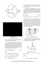
Shown in Figure 4.6 is a representation of anchor rod
pull out.
This failure mode occurs when an anchor rod (a
hooked rod or a nutted rod) is not embedded sufficiently
in the concrete to develop the tension strength of the rod.
The failure occurs in the concrete when the tensile
stresses along the surface of a stress cone surrounding
the anchor rod exceed the tensile strength of the con-
crete. The extent of the stress cone is a function of the
embedment depth, the thickness of the concrete, the
spacing between the adjacent anchors, and the location
of free edges of in the concrete. This failure mode is
presented in detail in Appendix B of ACI 349-90(4).
The tensile strength of the concrete, in ultimate strength
terms, is represented as a uniform tensile stress of
over the surface area of these cones. By examin-
ing the geometry, it is evident that the pull out strength
of a cone is equal to times the projected area, A
e
,
of the cone at the surface of the concrete, excluding the
area of the anchor head, or for the case of hooked rods
the projected area of the hook.
The dotted lines in Figure 4.16 represent the failure
cone profile. Note that for the rods in tension the cones
will be pulled out of the footing or pier top, whereas the
cones beneath the rods in compression will be pushed
out the footing bottom. This latter failure mode will be
discussed in the next section.
Depending on the spacing of the anchor rods and
the depth of embedment of the rods in the concrete, the
failure cones may overlap. The overlapping of the fail-
ure cones makes the calculation of A
e
more complex.
Based on AISC's Design Guide 7 the following
equation is provided for the calculation of A
e
which
covers the case of the two cones overlapping.
where
L
d
= the embedment depth, in.
c = the rod diameter for hooked rods, in., and 1.7
times the rod diameter for nutted rods (the 1.7
factor accounts for the diameter of the nut)
s = the rod spacing, in.
Thus, the design strength of two anchor rods in tension
is:
Eq. 4-13
where
-
0.85
f'
c
= the specified concrete strength, psi
When the anchor rods are set in a concrete pier, the
cross sectional area of the pier must also be checked.
Conservatively, if the pier area is less than A
e
then the
pier area must be used for A
e
in the calculation of
(Eq.4-13).
Also when anchor rods are placed in a pier the proj-
ected area of the cone may extend beyond the face of the
pier. When this occurs A
e
must be reduced. The pullout
strength can also be reduced by lateral bursting forces.
The failure mode shown in Figure 4.9 is representative
of these failure modes. These failure modes are also dis-
cussed in AISC's Design Guide 7. Conservatively A
e
can be multiplied by 0.5 if the edge distance is 2 to 3 in-
ches.
It is recommended that plate washers not be used
above the anchor rod nuts. Only heavy hex nuts should
be used. Plate washers can cause cracks to form in the
concrete at the plate edges, thus reducing the pull out re-
sistance of the anchor rods. The heavy hex nuts should
16
© 2003 by American Institute of Steel Construction, Inc. All rights reserved.
This publication or any part thereof must not be reproduced in any form without permission of the publisher.
Per ACI 318, (0.70) is the factor for bearing on con-
crete, and the value (2) represents the strength increase
due to confinement.
The design strength obtained from Eq. 4-14 must
be compared to the strength obtained from the failure
cones, Eq. 4-13. The lower value provides the ultimate
strength of the hooked rod to be used in the calculation
for the bending moment design strength associated with
rod pull out.
Eq. 4-15
4.2.7 Anchor Rod "Push Out" of the Bottom of the
Footing
Anchor rod push out can occur when the rod is
loaded to the point where a cone of concrete below the
anchor rod is broken away from the footing. This failure
mode is identical to anchor rod pull out but is due to a
compressive force in the rod rather than a tension force.
This failure mode does not occur when shim stacks are
used, when piers are present or when an additional nut is
placed on the anchor rods just below the top of the foot-
ing as shown in Figure 4.17.
Fig. 4.17 Prevention of Push Out
Shown in Figure 4.18 is the individual failure cone
for a nutted anchor rod, and the equation for A
e
. The de-
sign strength for this mode of failure is:
Fig. 4.18 Push Out Cones
Eq. 4-16
where
.75
f'
c
= the concrete compressive strength, psi
17
SECTION A
Fig. 4.16 Failure Cones
be tack welded to the anchor rods to prevent the rod from
turning during tightening operations.
For hooked anchor rods an additional check must be
made, because hooked rods can fail by straightening and
pulling out of the concrete. When this occurs, the rods
appear almost perfectly straight after failure. To prevent
this failure mode from occurring the hook must be of
sufficient length. The hook pullout resistance can be de-
termined from the following equation:
Eq.4-14
where
Hook Bearing Design Strength, kips
f'
c
= the concrete compressive strength, psi
the diameter of the anchor rod, in.
the length of the hook, in.
© 2003 by American Institute of Steel Construction, Inc. All rights reserved.
This publication or any part thereof must not be reproduced in any form without permission of the publisher.
The push out design strength for hooked anchor rods is
assumed to equal that of the nutted rod.
4.2.8 Pier Bending Failure
The design strength of a reinforced concrete pier in
bending is calculated using reinforced concrete prin-
ciples. The required procedure is as follows:
Determine the depth of the compression area.
C = T
0.85f'
c
ba = F
y
A
s
a
C - 0.85f'
c
ab
d = the effective depth of the tension reinforcing
= pier depth - cover - 1/2 of the bar diameter
C(d-a/2) Eq. 4-17
In addition, to insure that the reinforcing steel can
develop the moment, the vertical reinforcement must be
fully developed. Based on ACI 318-95 (12.2.2.), the re-
quired development length can be determined from the
equations below. These equations presume that ACI col-
umn ties, concrete cover, and minimum spacing criteri-
on are satisfied.
For the hooked bar in the footing:
Eq. 4-18
For straight bars (#6 bars and smaller) in the pier:
Eq. 4-19
For straight bars (#7 bars and greater) in the pier:
Eq. 4-20
where
1
dh
= the development length of standard hook in ten-
sion, measured from critical section to out-side
end of hook, in. (See Figure 4.19)
1
d
= development length, in.
f'
c
= specified concrete strength, psi
d
b
= the bar diameter, in.
If the actual bar embedment length is less than the
value obtained from these equations then the strength
requires further investigation. See ACI 318, Chapter 12.
4.2.9 Footing Over Turning
The resistance of a column footing to overturning is
dependent on the weight of the footing and pier, if any,
the weight of soil overburden, if any, and the length of
Fig. 4.19 Development Lengths
the footing in the direction of overturning. During
construction the overburden, backfill, is often not pres-
ent and thus is not included in this overturning calcula-
tion.
Shown in Figure 4.11 is a footing subjected to an
overturning moment.
The overturning resistance equals the weight, W
times the length, L divided by two, i.e.:
Eq. 4-21
where
= 0.9
W = P1+P2 + P3
P1 = the weight of any superimposed loads, kips
P2 = the weight of the pier, if any, kips
P3 = the weight of the footing, kips
After determining each of the individual design
strengths, the lowest bending moment strength can be
compared to the required bending moment to determine
the cantilevered column's suitability.
Example 4-1:
Determine the overturning resistance of a Wl2X65, free
standing cantilever column. Foundation details are
shown in Figure 4.20, and base plate details are shown in
Figure 4.21.
Given:
Leveling Nuts and Washers
4-3/4" ASTM A36 Hooked Anchor Rods with 12"
Embedment and 4" Hook
Pier 1'-4" x 1'-4" with 4 - #6 Vert, and #3 Ties @ 12" o/c
Footing 6'-0" x 6'-0" x l'-3"
18
© 2003 by American Institute of Steel Construction, Inc. All rights reserved.
This publication or any part thereof must not be reproduced in any form without permission of the publisher.
Fig. 4.20 Foundation Detail
Failure Mode 2: Base Plate Failure
Case B: Inset Anchor Rods - Weak Axis Capacity.
Based on the weld pattern and the geometry provided:
(See Figure 4.12)
Fig. 4.21 Base Plate Detail
No Overburden
Material Strengths:
Plates: 36 ksi
Weld Metal: 70 ksi
Reinforcing Bars: 60 ksi
Concrete: 3 ksi
Solution:
Failure Mode 1: Weld Design Strength
Compute (Neglecting Web Weld):
Failure Mode 3: Rupture of Anchor Rods
where
Failure Mode 4: Anchor Rod Buckling (Does not gov-
ern). (See Section 4.2.4.)
Failure Mode 5: Anchor Rod Nut Pull Through (Use
proper washers to eliminate this failure mode.)
19
© 2003 by American Institute of Steel Construction, Inc. All rights reserved.
This publication or any part thereof must not be reproduced in any form without permission of the publisher.
Failure Mode 6: Anchor Rod Pullout
= 628
in.
2
Check Pier Area:
A
e
= 16(16) = 256 in.
2
(Controls)
Note that edge distance will not control.
Check Hook Bearing Strength:
(Eq. 4-14)
= 2(0.7)(0.85)(3000)(0.75)(4)
= 10.7 kips
= 21.4 kips for two rods (Controls)
(Eq. 4-15)
= 8.9ft kips
Failure Mode 7 : Anchor Rod Push Out (Does not oc-
cur with pier.)
Failure Mode 8 : Pier Bending Resistance
Determine the depth of the compression area:
Failure Mode 9: Footing Overturning
(Eq.4-21)
where
0.9
W = P1+P2 + P3
P1 = 65(40)7 1000 = 2.6 kips (Column)
P2 = 0.15(1.33)1.33(3) = 0.8 kips (Pier)
P3 = 0.15(1.25)6(6) = 6.75 kips (Footing)
W = 10.15 kips, L = 6ft.
0.9(10.15)(6/2) = 27.4 ft. - kips
Comparing the above failure modes, the design moment
strength is 8.9 ft kips. The governing failure mode
would be anchor rod pull out.
Example 4-2:
Repeat Example 4-1 using outset anchor rods with em-
bedded nuts.
Increase the pier size to 24" x 24" to accommodate the
base plate. Increase the vertical reinforcement to be
8—#6
bars.
The
distance
from
the
anchor
rod to the
flange tip, L equals 2.83 in.
BasePlate 1" x 20" x l'-8"
= 60,000(2)(0.44)/0.85(3000)(16)
=
1.294
in.
C = 0.85f'
c
a
= 0.85(3000)(16)(1.294)71000
= 52.8 kips
= 52.8(13.75-1.294/2)
= 58 ft kips
Check Reinforcing Development length:
Req'd length in footing:
C(d-a/2) = 692 in kips (Eq. 4-17)
For the straight bars (#6 bars and smaller) in the pier:
20
(Eq. 4-5)
Failure Mode 2: Base Plate Failure
b
e
= 2L =
5.66
in. > 5.0 in.
Fig. 4.23 Base Plate Detail
Solution:
Failure Mode 1: Weld Design Strength
kips (Same as Example 4-1)
© 2003 by American Institute of Steel Construction, Inc. All rights reserved.
This publication or any part thereof must not be reproduced in any form without permission of the publisher.
Fig. 4.24 Base Plate Yield Line
= (0.9)(5)(l)
2
(36)/[(4)(5)]
= 16.2 kips
= (0.75)(0.9)(70)(.707)(5/16)(2)
= 20.9 kips
(Eq. 4-6)
(Eq.
4-7)
= (0.9)(50)(.221)(1)
1.5
- 9.94 kips (Controls)
= 2(9.94)( 16) = 318 in kips
= 26.5ft kips
Failure Mode 3: Rupture of Anchor Rods
(Eq. 4-8)
14.4 kips/rod ( Same as Example 1)
(Eq.4-11)
= 2(14.4)( 16)= 461 in kips
= 38.4 ft kips
Failure Mode 4: Anchor Rod Buckling (Does not gov-
ern)
Failure Mode 5: Anchor Rod Nut Pull Over (Use proper
washers)
Failure Mode 6: Anchor Rod Pull Out
(Eq. 4-13)
21
By inspection the pier area will control.
Check Pier Area:
A
e
= 20(20) = 400 in.
2
(Eq. 4-12)
= 2102 in kips (Eq. 4-15)
= 175 ft kips
Failure Mode 7: Anchor rod "push through" (Does not
occur due to pier)
Failure Mode 8: Pier Bending Resistance
Determine the depth of the compression area:
a = F
y
A
s
/.85f'
c
b
= 60,000(2)(0.44)/0.85(3000)(24)
= 0.863 in.
C = 0.85f
c
ab
= 0.85(3000)(0.863)(24)/1000
52.8 kips
(Eq.4-17)
C(d-a/2)
= 52.8(21.75-0.863/2)
= 1126 in kips
= 94 ft kips
Check Reinforcing Development length: (Same as Ex.
4-1)
Failure Mode 9: Footing Overturning:
where
(Eq.4-21)
0.9
W = P1+P2 + P3
P1 = 65(40) / 1000 = 2.6 kips (Column)
P2 0.15(2)(2)(3)= 1.8 kips (Pier)
P3 = 0.15(1.25)(6)(6) = 6.75 kips (Footing)
W = 11.15 kips
Comparing the above failure modes, the design moment
strength is 26.5 ft kips. The governing failure mode
would be base plate failure.
0.9(11.15)(3) = 30.2 ft kips
=
=
© 2003 by American Institute of Steel Construction, Inc. All rights reserved.
This publication or any part thereof must not be reproduced in any form without permission of the publisher.