autocad 2004 2d training manual
Bạn đang xem bản rút gọn của tài liệu. Xem và tải ngay bản đầy đủ của tài liệu tại đây (6.48 MB, 358 trang )
AutoCAD 2D Tutorial
- 1 -
AutoCAD
® 2004
2D Training Manual
Written by Kristen S. Kurland
Copyright © 2004
AutoCAD is a registered trademark of Autodesk, Inc.
Chapter 1 – Introduction to AutoCAD
Launching AutoCAD 4
Text and Graphics Screens 5
Cursor 6
Canceling a Command 6
Menus and Colors 7
Pulldown Menus 7
Cascading Pulldown Menus 7
Toolbars 8
To Float a Toolbar: 8
To Dock a Toolbar: 8
Help Tooltips 9
Loading Toolbars 9
Filedia 10
Status Bar 11
Pointing Device (Mouse) 12
Left Mouse Button 12
Right Mouse Button 12
Command Prompt 13
Typing a Command 13
Reissuing the Last Command 14
Undo 15
Redo 15
Function Keys 16
Accelerator Keys 17
On-Line Help 18
Chapter 2 – Introduction to Commands
Opening a Drawing 20
New Drawings 21
NEW Command 21
Saving Drawings 21
SAVE and SAVEAS 22
QUICK SAVE 23
File Safety Precautions 24
Autosave 24
Temporary Files 24
Security Options 25
Exiting AutoCAD 26
QUIT 26
Chapter 3 – Draw Commands
Line Command 28
Cartesian Coordinate System 29
Absolute Coordinates 30
Relative Coordinates 30
Polar Coordinates 30
Orthogonal Lines 31
Direct Distance Entry 32
Circles and Arcs 33
Circle Command 33
Arc Command 34
Command Aliases 35
Line Alias 35
Circle Alias 35
Arc Alias 35
Chapter 4 – Erase and Selection Sets
Erase and Selection Sets 36
Erasing Objects 37
Selection Set Options 38
Window and Crossing 38
Remove from Selection Set 39
OOPS 40
Delete Key 40
Chapter 5 – Basic Display Commands
Zoom 41
Pan 42
Redraw 44
Blipmode 44
Regen 44
Chapter 6 – Drawing Aids
SNAP Command 45
Turn Snap On/OFF 46
SNAP Angle 47
Grid Command 47
Turn Grid On/Off 48
Polar Tracking 49
Chapter 7 – Object Snapping
Running Object Snaps 50
Object Snap Settings 52
Osnap Settings 54
Aperture 54
Chapter 8 – Setting Up a Drawing
List Command 54
Measuring Distances 55
ID Command 57
UNITS Command 58
Drawing Limits 59
Plot Scales and Paper Sizes 60
Chapter 9 – Plotting
Plot Command 62
Plot Settings 65
Adding a Plotter 66
Plotter Manager Wizard 66
Choosing a Plotter Driver 67
Importing a .PCP or .PC2 file 67
Define a Port 68
Saving a Plot Configuration Name 68
Plot Styles 69
Add a Plot Style 69
Named Plot Styles 72
Chapter 10 – Edit Commands
Move Command 72
Copy Command 75
Previous Selection 76
Offset Command 77
EXTEND 79
TRIM 80
Edgemode 81
MIRROR 82
Mirrtext 82
ROTATE 83
Reference Angle Rotation 85
SCALE 86
Scale by Specifying Length 87
Chapter 11 – Text
Text Command 87
Text Justification 90
Style Command 92
Font Files 93
Multiline Text 94
Mtext Command 94
Type text or change an MTEXT setting. 94
MTEXT options: 95
Editing Text 96
DDEDIT 96
Special Control Codes 97
Spell Check 98
Scale Text 99
Chapter 12 – Layers, Linetypes, and Colors
Introduction to Layers and Layer Dialog Box 100
Changing the Layer of an Object 103
Making a Layer Current 103
Layer Previous 104
Layer States 106
Color Command 106
Loading and Changing Linetypes 108
Lineweights 109
Loading and Changing Lineweights 109
Object Properties 110
Chapter 13 – More Edit Commands
Stretch 114
Fillet 116
Chamfer 117
Array 118
Rectangular Array 118
Polar Array 119
Lengthen 121
Chapter 14 – Advanced Display Commands
Transparent Commands 123
Multiple Command 124
Calculator (CAL Command) 125
Chapter 15 – Polylines
PLINE options: 129
Editing Polylines 130
Edit Vertex Options 131
Editing Multiple Polylines 132
Explode Command 133
Turning Lines into Polylines 134
Chapter 16 - More Draw Commands
Polygon 136
Rectangle 137
Spline 138
Spline options: 139
Editing Splines 140
Covert PLINE to Spline 141
Donut 142
Ellipse 143
Multilines 145
MLINE Command 145
Multiline Justifications 146
Multiline Styles 147
Editing Multilines 148
Construction Line 149
Ray Command 150
Chapter 17 - Crosshatching
BHATCH Command 152
BHATCH options: 153
Advanced Hatch Options 154
Define Boundary Set 154
Hatchstyle 154
Boundary Options 154
Gradient Hatch 155
HATCHEDIT 156
Inherit Hatch 157
Chapter 18 – Regions and Boundaries
Boundary Command 159
Region Command 160
Chapter 19 - Blocks and Attributes
Creating Local Blocks (BMAKE) 163
Inserting Blocks 164
Typing Insert (-INSERT) 165
Control the Color and Linetype of Blocks 166
Wblock Command 166
Purge 168
Defining Attributes 169
Editing Attributes 170
Block Attribute Manager 171
Synchronize Attributes 172
Enhanced Attribute Extract 173
Chapter 20 - Design Center and Tool Palettes
Design Center Overview 175
Design Center Blocks 177
Hatching from the Design Center 178
Chapter 21 - Point, Divide, and Measure
Point Styles 180
Point Command 182
Divide 183
Measure 185
Chapter 22 - Grips
Grips Overview 187
Entity Grips 187
Unselected Grip 187
Selected Grip 187
Cancelling Grips 188
How To Use Grips 189
Grips Settings (DDGRIPS Command) 191
Chapter 23 - Advanced Selection Commands
Selection Modes 194
Noun/Verb Selection 194
Use Shift to Add to Selection 194
Press and Drag 194
Implied Windowing 195
Object Grouping 195
Associative Hatch 195
Groups 196
Object Selection Cycling 197
Draw Order 199
Object Filters 200
Quick Select 201
Layer Filters 202
Point Filters 203
Chapter 24 - External References
External Reference Files Overview 205
The following are Xref characteristics: 205
Attaching Xrefs 207
Xref Layers 208
Layer Dialog Box 208
Xclip 209
Xclipframe 210
Binding an Xref 211
To Bind an Xref: 211
Xbind 212
Editing Xrefs (Xref Manager) 213
Detaching Xrefs 213
Unload an Xref 213
Reload an Xref 214
Opening Xrefs to Edit 214
Overlay an Xref 215
Chapter 25- Raster Images
Inserting Images 217
Image Appearance 25.2 219
Adjusting Image Appearance 219
Image Transparency 219
Erasing Images 220
Image Quality 220
Clipping Images 221
Chapter 26- Dimensions
Linear Dimensions 222
Aligned Dimensions 224
Radial Dimensions 225
Angular Dimensions 225
Continued and Baseline Dimensions 226
Leaders 227
Leader Settings 228
Quick Dimensions 229
Modifying Dimensions 230
DDEDIT 230
Stretching Dimensions 230
DIMTEDIT 231
Dimension Edit Commands 231
Ordinate Dimensions 232
Chapter 27- Dimension Styles
Creating Dimension Styles 234
Lines and Arrows 235
Text 236
Primary Units 237
Alternate Units 238
Tolerances 239
Fit 240
Dimscale 240
Dimension Overrride 242
Dimension Variables 243
Chapter 28 – Views and Viewports
Named Views 246
Ddview Command 247
Typing the View Command 248
View options: 248
Plotting Named Views 248
Viewports 249
Vports Command 249
Viewport options 250
Chapter 29 - Model Space and Paper Space
Creating a Layout 251
Creating Mulitple Layouts 254
Mview Command 255
Irregular Shaped Viewports 256
Model Space 257
Paper Space 258
Scales - Zooming in Model Space 259
Adding Text in Paper Space 260
Plotting in Paper Space 261
Layout Wizard 262
Tilemode 265
Viewport Layers 266
Chapter 30 - Options Menu
Files 267
Open and Save 270
Plotting 270
Plotting 271
System 271
User Preferences 273
Drafting 273
Selection 275
Chapter 31 - Drawing Utilities
AUDIT 276
RECOVER 278
PURGE 279
Rename 280
Chapter 32 - Data Management
Importing Files 282
Exporting Files 283
Chapter 33 - OLE and External Applications
Copying from AutoCAD 285
Print Screen 286
OLE Linking to AutoCAD 287
Hyperlinking 289
Opening a Hyperlink 289
Chapter 34 - Communication and Collaboration Tools
Plotting to the WEB 292
Configuring DWF Files 293
Publish Command 294
Publishing WEB Pages 295
e-Transmit 300
i-Drop 301
Chapter 35 - AutoCAD WEB
AutoCAD DWF Viewer 303
Volo View 304
CAD Viewer 305
Internet Explorer 306
AutoCAD Related WEB Sites 307
Chapter 36 - Customization
Create New Toolbars 312
Pausing for User Input Example 317
AutoLISP Web Sites 322
Chapter 37 - External Applications and LISP Routines
Loading LISP Files 323
Loading Menus with LISP Routines 324
Chapter 38 - Slide Shows
MSlide Command 326
Scripts 328
Pausing a Slide 328
Running a Script in AutoCAD 329
Repeating a Script 329
Chapter 39 - CAD Standards
Redline Markup Language 335
Revision Cloud 337
Wipeout 338
Chapter 40 - Isometrics
Isometric Cursor 339
Isoplane Toggle 341
Isometric Circles 342
Isometric Text 343
Isometric Dimensions 345
AutoCAD 2D Tutorial
- 2 -
Chapter 1
Introduction to AutoCAD
AutoCAD 2D Tutorial
- 3 -
1.1 Launching AutoCAD
1. Choose Start from the Windows program manager.
2. Choose Programs, Autodesk ,AutoCAD 2004.
3. Click the AutoCAD 2004 for Windows icon.
or
4. Choose the AutoCAD 2004 icon from the desktop.
AutoCAD 2D Tutorial
- 4 -
1.2 Text and Graphics Screens
The graphics screen and the text screen are two different screens
available in the drawing editor.
1. Press Function key F2 on the keyboard.
TIPS:
Be sure the Model Tab is highlighted at the bottom of the drawing window.
“Layouts” will be covered in a later session.
The Cursor must be in the drawing window in order to select objects.
Maximize the AutoCAD windows to be full screen. This will make the
drawings bigger and easier to read.
Use ALT + TAB to move between Windows applications.
AutoCAD 2D Tutorial
- 5 -
1.3 Cursor
Controls the size of the crosshair. The allowable range is from 1 to 100
percent of the total screen. At 100% the ends of the crosshair are never
visible. When the size is decreased to 99% or below, the crosshairs
have a finite size, and the crosshairs’ ends are visible when moved to
the edge of the graphics area. The default size is 5%.
1. Choose Tools, Options…
2. Click the Display TAB.
3. Drag the slider bar in the lower left corner of the dialog to
set the cursor size.
1.4 Canceling a Command
1. Press the ESCAPE (ESC) key on the keyboard.
TIP: Pressing ESC twice clears nested commands.
AutoCAD 2D Tutorial
- 6 -
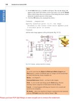
1.5 Menus and Colors
Pulldown Menus
1. Click On the desired Pulldown menu.
2. Click On the command to be executed from the pulldown.
Cascading Pulldown Menus
1. Click On a command that has a cascading menu
(menus with an arrow to the right of the menu)
2. Click On the command to be executed.
Cascading
Pulldown
AutoCAD 2D Tutorial
- 7 -
1.6 Toolbars
Toolbars can be docked on the screen or they can float about the screen.
To Float a Toolbar:
1. Choose the gray border surrounding each tool.
2. Drag the toolbar to any area on the screen.
To Dock a Toolbar:
1. Choose the title or gray border of the toolbar.
2. Drag the toolbar to the top, bottom, left, or right area of the
graphics display.
TIPS:
-Holding the CTRL key while dragging will prevent docking.
-Toolbars are often a faster way of accessing a command.
-Clicking on an icon with the right mouse button will show a list of all
available toolbars.
Docked
Toolbars
Floating
Toolbars
AutoCAD 2D Tutorial
- 8 -
Help Tooltips
1. Move The mouse to the toolbar but do not pick the button.
Loading Toolbars
1. Choose View, Toolbar
or
2. Type TOOLBAR at the command prompt
Command: TOOLBAR
3. Choose the desired toolbar to load.
AutoCAD 2D Tutorial
- 9 -
1.7 Filedia
Some commands evoke dialog boxes which are typically used to enter
information or change settings. The filedia command suppresses display
of the file dialog boxes.
1. Type FILEDIA at the command prompt.
Command: filedia
2. Enter new value for FILEDIA <1>: 0
0 Dialog boxes are not displayed. You can still request a file dialog box to
appear by entering a tilde (~) in response to the command's prompt.
1 Turns on dialog boxes.
0 Turns off dialog boxes.
TIPS:
-Menu choices that are followed by three dots ( ) typically invoke a dialog
box. For example View, Toolbars calls a dialogue box.
-To use the command line version of a dialog box command,
enter minus (-) in front of the command.
AutoCAD 2D Tutorial
- 10 -
1.8 Status Bar
The Status Bar is the area below the command line that shows messages
as well as coordinates, modes, and the current time.
To activate SNAP, GRID, ORTHO, OSNAP, MSPACE, PSPACE, and
TILE, you must double-click on the mode to change.
TIP:
• Right click on the status bar to see the options.
Status Bar
AutoCAD 2D Tutorial
- 11 -
1.9 Pointing Device (Mouse)
AutoCAD uses either a mouse or digitizing tablet to select objects in a
drawing.
Left Mouse Button
Used to pick or select objects
1. Click the left mouse button to select an object area in the
drawing.
2. Press ESC twice to deselect an object (or to cancel a
command).
Right Mouse Button
Used to enter a command, repeat last command, or access shortcut
menus.
1. Click the right mouse button.
TIPS:
• SHIFT + the right mouse button brings up the object snap menus.
• Various screen locations for the mouse brings up different menus.
LEFT
MOUSE
RIGHT
MOUSE
AutoCAD 2D Tutorial
- 12 -
1.10 Command Prompt
Typing a Command
All AutoCAD commands can be typed in at the command line. Many
commands also have one or two letter aliases that can also be typed as
shortcuts to the commands.
1. Type the desired command at the command
prompt.
Command : LINE
or
2. Type the command’s alias.
Command: L
3. Press ENTER.
4. Type an option at the command prompt.
TIP:
Many AutoCAD commands require you to press ENTER to complete the
command. You know you are no longer in an AutoCAD command when
you see a blank command line.
Command
Prompt
AutoCAD 2D Tutorial
- 13 -
Reissuing the Last Command
The last used AutoCAD command can be re-entered by one of the
following three methods of ENTER. The ENTER key on the keyboard will
always act as ENTER, the SPACEBAR and RIGHT MOUSE will act as
enter most of the time (exceptions include placing TEXT).
1. Press the ENTER key on the keyboard
or
2. Press the Space bar on the keyboard.
or
3. Click the right mouse button.
AutoCAD 2D Tutorial
- 14 -
1.11 Undo
Reverses the last action.
1. Choose Edit, Undo.
or
2. Click the Undo icon.
or
3. Press CTRL + Z.
4. Type U at the command prompt to undo the
last command.
Command: U
Redo
Reverses the effects of a single UNDO or U command.
1. Choose Edit, Redo.
or
2. Click the Redo icon.
or
3. Type REDO at the command prompt to redo the
last undo command.
Command: REDO
TIPS:
-UNDO has no effect on some commands and system variables, including
those that open, close, or save a window or a drawing, display
information, change the graphics display, regenerate the drawing, or
export the drawing in a different format.
-REDO must immediately follow the U or UNDO command.