Phản ứng của sợi thép bê tông cốt thép chịu AIR
Bạn đang xem bản rút gọn của tài liệu. Xem và tải ngay bản đầy đủ của tài liệu tại đây (560.95 KB, 6 trang )
RESPONSE OF STEEL FIBER REINFORCED CONCRETE SUBJECTED TO AIR
BLAST LOADING
Mohammed Alias Yusof(1), Norazman Mohamad Nor(1), Ariffin Ismail(2), Muhamad Fauzi
Muhamad Zain(3), Risby Mohd Sohaimi(1), Ng Choy Peng(1)
(1)Faculty of Engineering, Universiti Pertahanan Nasional Malaysia, Kem Sungai Besi, 57000 Kuala Lumpur
Email:
(2)Faculty of Defence Management and Studies, Universiti Pertahanan Nasional Malaysia, Kem Sungai Besi, 57000
Kuala Lumpur
(3)Faculty of Engineering and Built Environment, Universiti Kebangsaan Malaysia, 43600 Bangi, Selangor
ABSTRACT
This paper investigates the behaviour of concrete panel subjected to air blast loading. The test
component include normal reinforced concrete (NRC) and also steel fibre reinforced concrete
(SFRC) with a fibre content of 1.5 % in volume percentages. Field blast test were conducted
using 1kg of plastic explosive (PE4) at standoff distance of 0.6 meter. Failure modes of each
specimen were investigated and are presented in this paper. The experimental results indicate
that incorporation of steel fibres in concrete have significantly improved the blast resistance of
concrete as compared to plain reinforced concrete.
Key word : Steel fiber concrete, Air blast loading, normal concrete.
INTRODUCTION
Recent terrorist attack on Moscow Metro Train (2010), Marriott Hotel in Jakarta (2009), and
Mumbai (2008) had shown that the destruction of the hotels and other facilities such as public
transport and military base has become target of the terrorist [1-3]. In most of the cases, the
terrorist used explosives located in the vehicle at a close distance from the target. The explosion
creates intense shock waves which propagate outward at supersonic velocity accompanied by
released of heat and light that induced pressure on the structural members and causes significant
damaged to the structure and loss of life. There are a number of methods to stop the terrorist
attack. One of the methods is gathering information on the terrorist and stop the attack before
it take place, another way is protect building from damaged is by incorporating blast resistance
design and also retrofitting of the existing structure [4].
This area of research is currently receiving more attention from many structural engineers in
which they began to consider blast loading and also blast resistance materials in their design in
order to protect important building and structures from such attacks. Concrete is one of the most
widely used construction material for structures because it possesses considerable mass per unit
cost compared to other construction materials, and has excellent fire-resistance and is able to
absorb large amounts of energy [5] However, one of the disadvantages of concrete it have a very
low resistance againts tensile stress and also posses low ductility . From previous research it was
found that mechanical properties of the concrete can be inproved by adding fibers into the mix.
Otter & Naaman (1987) reported that the addition of fiber in the concrete have significant effect
on strenght and toughness of concrete.[6] The test results of Nagarkar et. al (1988) indicated that
the compressive, split tensile and flexural strenght of concrete incresed by the addition of fiber.
[7].
The objective of this reseach is to investigate the response of Steel fiber reinforced concrete
(SFRC) subjected to air blast loading. In this study two type of concrete specimens, which are
normal reinforce concrete (NRC) and also steel fiber reinforced concrete (SFRC) were tested
using charge weight of 1 kg explosive at a standoff distance of 0.6 meter to determine their
response to air blast loading. After each test, the failure mode of the specimen was recorded and
examined. The details are presented in this paper.
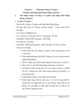
BLAST WAVE PHENOMENA
An explosion is as a large-scale, rapid, and sudden release of energy. As the explosive detonates,
it creates a shock wave that travels at supersonic velocity and at the same time the pressure
around the area increases. The shock wave expands until it hits the test structure and is reflected
upwards. As the shock wave hits the test structure, pressure decreases rapidly. As a result of the
sudden decrease in pressure, a vacuum were created around the blast area which drags pressure
on the surface of the test structure and also the surrounding area. The vacuum creates high
suction winds that carry fragments and debris far from the blast source. This blast also creates
missiles ground shock, and cratering at the surrounding area depending on the capacity of the
explosive. [8]. The blast phenomenon is as shown in the Fig 1.
Fig 1: Typical blast wave profile [8]
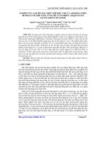
EXPERIMENTAL PROGRAM
The concrete specimen used for the experiment is Normal Reinforced Concrete (NRC) and Steel
fiber reinforced concrete panel (SFRC) as shown in Fig 2.
Fig 2. Typical Plan and section for the panel
The specimen was reinforced with 10 mm diameter steel at 200 mm centre-to-centre in both
ways. The specimen measures at 600 mm × 600 mm and a thickness of 100 mm . Ordinary
Portland cement, crushed stone coarse aggregate having maximum size of 10mm and also river
sand were used. The steel fiber reinforced concrete, mix incorporated volume fraction of 1.5 %
of hooked-end steel fibers which is made of mild carbon steel as shown in Fig 3.
Fig. 3. Hooked end steel fiber
The mix consists of the proportion of cement: water: aggregate: sand was 357:160: 997:534:
kg/m3. In the production of concrete, firstly the aggregate and sand was put into the mixer and
mixed for a few minutes and then cement and water were added into the mix. Finally the fibres
were added in small amounts to avoid fibre balling and to produce the concrete with uniform
material consistency and good workability.
The freshly mix steel fibre reinforced concrete was placed in two equal layers into mould to cast
a standard 150mm × 150mm × 150mm cube and 150mm × 300mm cylinder concrete specimen
for a compressive strength test and a split tensile test and also into a 100mm ×100mm ×500 mm
beam mould for a flexure strength test. Each layer was consolidated using a vibrating table. At
the end of 24 hours after consolidating, the specimen was removed from the mould and cured
in water for 28 days. Finally the NRC and SFRC were poured separately into the panel mould
of 600 mm × 600 mm × 100 mm. The NRC and SFRC panels were later removed from the
mould after consolidation and cured with wet gunny sacks for 28 days before the field blast test.
Table 1 shows the results of the average compressive strength tests, flexural strength tests and
split tensile strength tests for both the NRC and SFRC specimens.
Table 1 : Test result for NRC and also SFRC
Average strength NRC SFRC
Compressive 31 38.5
Flexural (MOR) 3.5 6.0
Split Tensile 3.0 4.5
FIELD BLAST TEST PROGRAM
A field blast test was conducted at a disclosed military facility. In the test two steel I beam
support of a length 800 mm each of was fabricated to support the specimen. The supports were
fixed to the existing heavy reinforced concrete structure located at the blasting site. The concrete
panel was then fixed to the steel support frame as shown in Fig 4. The explosive is suspended in
mid air at 600mm stand-off distance towards the panel. The blast test set up is shown in Fig. 5.
600mmve600mmve600mmve ExplosiveExplosiveExplosive Test panelTest panelTest panel
Fig 4. Steel support frame Fig 5. Test set up
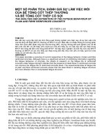
RESULTS AND DISCUSSION
At the end of each test, the failure pattern of specimen were recorded. A set of photographs of
specimens is presented in Fig 6.
(a)
Back face of NRC (b) Back face of SFRC
Fig. 6. Failure pattern of NRC and SFRC
Specimen NRC:This specimen failed in shear mode. Two large cracks developed on the back
face of the specimen. A number of smaller cracks were also observed on both the front and rear
faces.This is because the normal reinforced concrete have a very low resistance againts tensile
stress and also low ductility
Specimen SFRC: Basically there is minor damaged on back face of this specimen.The
specimen shows high resistance to blast loading. This is because of by incorporating the fibers
into concrete restrain the initiation and propagation of crack by the bridging effect of steel fibers..
The bridging effect observed in the panel is shown in Fig 7.
Steel Fiber bridge crackSteel Fiber bridge crackSteel Fiber bridge crack
Fig 7 : Bridging action of steel fiber on concrete .
CONCLUSION
Field blast tests have been conducted on the normal fiber reinforced concrete panel (NRC)
and also steel fibre reinforced concrete (SFRC) panel The experimental result indicates that
incorporation of steel fibres in concrete has significantly improved the blast resistance of
concrete as compared to normal (NRC).
ACKNOWLEDGEMENTS
The authors wish to gratefully acknowledge the support Science and Technology Research for
Defence (STRIDE) for providing support and and test fasilities during the feild test program.