High Order Sliding Mode Neurocontrol for Uncertain Nonlinear SISO Systems - Theory and Applications
Bạn đang xem bản rút gọn của tài liệu. Xem và tải ngay bản đầy đủ của tài liệu tại đây (924.62 KB, 22 trang )
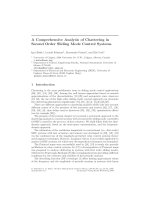
High Order Sliding Mode Neurocontrol
for Uncertain Nonlinear SISO Systems: Theory
and Applications
Isaac Chairez
1
, Alexander Poznyak
1
, and Tatyana Poznyak
2
1
Department of Automatic Control CINVESTAV-IPN, M´exico, D.F.
{ichairez,apoznyak}@ctrl.cinvestav.mx
2
Superior School of Chemical Engineering and Extractive Industries, M´exico, D.F.
1 Introduction
Uncertainties in dynamic systems are common in real applications, provoking
substantial troubles in any control realization and being a source of instability
or poor performance for tracking or regulation problems. Considerable research
efforts had been undertaken on control designing for uncertain nonlinear dynamic
systems over the last thirty years. There are several approaches to design and
construct a control in this situation. Among them, the more effective are the
Artificial Neural Networks (ANN) and the Sliding Mode (SM) technique with
all possible variants within (Integral Sliding Mode, Higher Order Sliding Mode,
etc.). Such combination seems to be very promising [21], [28] because it provides
a new instrument for identification, state estimation and control of many classes
of uncertain systems affected by external perturbations. This chapter deals with
the realization of this idea and suggests an adaptive control designing based
on both Differential Neural Network Observation and High Order Sliding Mode
Technique. Below this approach is referred to as High Order Sliding Mode Neural
Control (HOSMNC).
1.1 Classical and Unconventional Sliding Mode
Many physical systems naturally require the use of discontinuous terms in their
dynamics or in their control actions. The keystone of this approach is the the-
ory of differential equations with discontinuous right-hand side [5]. Based on
it, the switching logic is designed in such a way that a contracting property
dominates the controlled dynamics leading thus to stabilization on a desired
manifold, which induces desirable trajectories. These principles constitute the
main idea in developing one of the most effective approach to identify and con-
trol a wide class of uncertain nonlinear systems: Sliding Mode Control (SMC)
[30], [31]. The essential feature of this technique is the application of discontinu-
ous feedback laws to reach and maintain the closed-loop dynamics on a certain
manifold in the state space (the switching surface) with some desired properties
G. Bartolini et al. (Eds.): Modern Sliding Mode Control Theory, LNCIS 375, pp. 179–200, 2008.
springerlink.com
c
Springer-Verlag Berlin Heidelberg 2008
180 I. Chairez, A. Poznyak, and T. Poznyak
for the system trajectories. This control offers many advantages comparing to
other identification and control techniques: good transient behavior, the need for
a reduced amount of information in comparison to classical control techniques,
unmodeled disturbance rejection capability, insensitivity to plant nonlinearities
or parameter variations, remarkable stability and performance robustness.
There are two important drawbacks in real sliding-mode controllers imple-
mentations:
- the first one is related to the reaching phase which could induce control
actions with high values, this fact could provoke the real controlled system to
reach its maximum operation limits (dissipated energy, physical restrictions, etc.)
leading to a bad performance on the close-loop dynamics;
- the second one deals with the actuators which have to cope with the high
frequency bang-bang type of control actions that could produce premature wear
or even breaking.
However the last drawback-phenomenon, called chattering, could be reduced
using several techniques such as nonlinear gains, dynamic extensions, dynamic
filtering and high-order (or unconventional) sliding modes [3], [6]. This chapter
exactly describes the application effect of the last technique.
The standard sliding mode (first order or 1-Sliding Mode) may be implemented
only if the relative degree of the sliding variable s is 1 with respective to the
measurable variable. It is well known that it provokes a high frequency switching
(chattering effect) of the designed control. Therefore, the traditional notion of
sliding mode control has been extended and the concept of 2-Sliding Mode and
higher order sliding modes (HOSM) has been developed [2], [15]. With these
controllers, a sliding control of an arbitrary smoothness order can be achieved.
Shortly speaking, higher order sliding modes remove the restrictions faced by
standard sliding mode, while keeping its main properties.
1.2 Differential Neural Networks
Artificial Neural Networks (ANN) have shown good identification properties in
the presence of some uncertainties or external disturbances. There are known two
type of NN: static one, using the, so-called, back-propagation technique [8] and
dynamic neural networks (DNN) [19], [27]. The first one deal with the class of
global optimization problems trying to adjust the weights of such NN to minimize
an identification error. The second type exploits the feedback properties of the
applied DNN and permits to avoid many problems related to global extremum
search, transforming the learning process to an adaptive feedback design [21]. If
the mathematical model of a considered process is incomplete or partially known,
the DNN-approach provides an effective instrument to attack a wide spectrum
of problems such as identification, state estimation, trajectories tracking an etc.
[17], [21].
Dynamic neuro-observers are studied in [21]. In [24] the SMC approach is used
to obtain the algebraic (non differential) weight-learning procedure for on-line
High Order Sliding Mode Neurocontrol 181
identification of a nonlinear plant (a model design) with completely available
states. DNN observers containing sign-term are considered also in [23].
2 DNN Observation with Stable Learning
2.1 Class of Nonlinear Systems
The class of uncertain nonlinear SISO systems considered throughout this chap-
ter is governed by a set of n nonlinear ordinary differential equations (ODE) and
the algebraic state-output mapping given by
˙x
t
= f (x
t
,u
t
)+ξ
1,t
,y
t
= Cx
t
+ ξ
2,t
(1)
where x
t
∈
n
is the system state at time t ≥ 0, y
t
∈is the system output,
u
t
∈is the control action, C ∈
1×n
is an a priory known output matrix.
The vectors ξ
1,t
∈
n
and ξ
2,t
∈represent the state and output deterministic
bounded (unmeasurable) disturbances, i.e.,
ξ
j,t
2
Λ
ξ
j
≤ Υ
j
,Λ
ξ
1
∈
n×n
,Λ
ξ
1
= Λ
ξ
1
> 0,Λ
ξ
2
> 0,Υ
2
=1 (2)
Suppose that
f (x, u) − f (w, v)≤L
1
x −w + L
2
|u −v|
f (0, 0)
2
≤ C
1
,w,x∈
n
; u, v ∈, 0 ≤ L
1
,L
2
< ∞
(3)
which automatically implies the following property
f (x, u)
2
≤ C
1
+ C
2
x
2
+ C
3
u
2
,C
k
∈
+
,k= 1, 3(4)
valid for any x and u. Notice that (1) always could be represented as
˙x
t
= f
0
(x
t
,u
t
| Θ)+
˜
f
t
+ ξ
1,t
,
˜
f
t
:= f (x
t
,u
t
) −f
0
(x, u | Θ)(5)
where f
0
(x, u | Θ)isthenominal dynamics while
˜
f
t
is a vector called the mod-
elling error. Here the parameters Θ are suggested to be adjusted to minimize the
approximation of the nominal part. In particular and according to the DNN ap-
proach [21], the nominal dynamics may be defined within the following nonlinear
structure
f
0
(x, u | Θ)=Ax + W
∗
1
σ (x
t
)+W
∗
2
ϕ (x
t
) u
A ∈
n×n
,W
∗
1
∈
n×l
,W
∗
2
∈
n×s
σ (·) ∈
l×1
,ϕ(·) ∈
s×1
,Θ:= [W
∗
1
| W
∗
2
] ∈
n × (n+l+s)
(6)
The validation of such approximation is based on the approximative Kolmogorov
Theorem [12], the Stone-Weierstrass Theorem [25] on sigmoidal approximation
and the Lipschitz property (in fact, ”quasi-linearity”) (3). Here the matrix A is
182 I. Chairez, A. Poznyak, and T. Poznyak
selected as a stable one and such that the pair (A, C) is observable. The vector-
functions σ (·):=[σ
1
(·) , , σ
l
(·)]
and ϕ (·):=[ϕ
1
(·) , , ϕ
s
(·)]
are usually
constructed with sigmoid function components (following the standard neural
networks design algorithms):
a
⎛
⎝
1+b exp
⎛
⎝
−
n
j=1
c
j
x
j
⎞
⎠
⎞
⎠
−1
, a,b,c
j
∈
+
,x=[x
1
, , x
n
]
(7)
The nonlinear functions σ (x)andϕ (x)satisfy
σ (x
1
) −σ (x
2
)
2
≤ l
σ
x
1
− x
2
2
, ϕ (x
1
) −ϕ (x
2
)
2
≤ l
ϕ
x
1
− x
2
2
0 <ϕ
−
≤ϕ (x)≤ϕ
+
(8)
The admissible control set is supposed to be described by a state estimated
feedback controllers defined (in general) by:
U
adm
:=
u = u (ˆx):u
2
≤ v
0
+ v
1
ˆx
2
Λ
s
u
(9)
(0 <Λ
s
u
=[Λ
s
u
]
,Λ
s
u
∈
n×n
)whereˆx ∈
n
is a state estimation defined by any
suitable (adaptive and stable) nonlinear observer. By (9) and in view of the (4)
property, the following upper bound for the modelling error dynamics
˜
f
t
∈
n
takes place:
˜
f
2
Λ
f
≤
˜
f
0
+
˜
f
1
x
2
Λ
¯
f
+
˜
f
2
ˆx
2
Λ
˜
f
,
˜
f
0
,
˜
f
1
,
˜
f
2
∈
+
(10)
Λ
¯
f
,Λ
˜
f
∈
n×n
, 0 <Λ
˜
f
= Λ
˜
f
0 <Λ
¯
f
= Λ
¯
f
. Assumed that:
A1. A is a stable matrix.
A2. Any of unknown controlled SISO ODE has solution and it is unique, that is
(3)and(4)hold.
A3. The unmeasured disturbances for the uncertain dynamics ξ
1,t
and the output
signal ξ
2,t
satisfy (2) and they do not violate the existence of the ODE
solution (1).
A4. Admissible controls satisfy the sector condition (9), and again, do not violate
the existence of the solution to ODE (1).
2.2 DNN Observer with Variable Structure Term
Defined the DNN observer which can be used to reproduce the unknown x
t
vector as follows:
d
dt
ˆx
t
= Aˆx
t
+ W
1,t
σ (ˆx
t
)+W
2,t
ϕ (ˆx
t
) u
t
+ K
1
[y
t
− Cˆx
t
]+K
2
y
t
− Cˆx
t
y
t
− Cˆx
t
A ∈
n×n
,K
1
,K
2
∈
n×1
,W
1,t
∈
n×l
,W
2,t
∈
n×s
∀t ≥ 0,
(11)
High Order Sliding Mode Neurocontrol 183
where ˆx
0
is fixed and the weight matrices (W
j,t
, j =1, 2) are updated by a
nonlinear learning law
˙
W
j,t
= Φ
j
(W
j,t
, ˆx
t
,y
t
,u
t
,t| Θ) (12)
to be designed. Notice this nonlinear adaptive observer reproduces (as it usu-
ally called in the state estimation theory) the nominal plant structure (or its
approximation) with two additional output based correction terms: one propor-
tional to the output error and the second one known as a unitary corrector. As a
consequence, when y
t
= Cˆx
t
, the ODE (11) should be attended as a differential
inclusion (see [5]). The pair of correction matrices K
1
and K
2
should be selected
as it is described below.
2.3 Problem Statement
The main idea is to force the uncertain nonlinear system (1) to track a de-
sired reference signal by means of a sliding mode controller using the estimated
states provided by a differential neural network observer. This problem can be
formulated as the solution of the following two subproblems:
• Under the assumptions A1-A4 for any admissible u
t
control strategy (9),to
select the adequate matrices A, K
1
, K
2
and the update law (12) (including
the selection of W
∗
j
,j=1, 2) in such a way that the upper bound for the
averaged estimation error β defined as
β :=
lim
t→∞
1
t + ε
ss
t
s=0
ˆx
s
− x
s
2
Q
0
ds ε
ss
> 0,Q
0
= Q
0
> 0 (13)
wouldbeaslessaspossible.
• Using the obtained state estimations, to construct a feedback controller ˜u
t
=
˜u
t
(ˆx
s
) |
s∈[0,t]
such that the averaged (or, non averaged, if feasible) tracking
performance index
J (˜u):=
lim
t→∞
1
t + ε
ac
t
s=0
x
∗
s
− ˆx
s
2
˜
Q
ds, ε
ac
> 0,
˜
Q
=
˜
Q>0 (14)
would be small enough.
Here x
∗
is the state vector of a suitable desired dynamics given by:
˙x
∗
t
= φ (t, x
∗
t
) ,x
∗
0
is fixed, x
∗
t
∈
n
,φ(·, ·):
n+1
→
n
(15)
2.4 Adaptive Weights Learning Law with Bounded Dynamics
To adjust the given neuro-observer (11), let us apply the following learning law:
184 I. Chairez, A. Poznyak, and T. Poznyak
˙
W
1,t
= −k
1,t
e
t
C + σ
(ˆx
t
)
˜
W
1,t
P
1
N
δ
C
Λ
−1
ξ
2
C + Λ
1
N
δ
P
1
σ
(ˆx
t
)
+k
1,t
[2σ (ˆx
t
)ˆx
t
P
2
]
σ
(ˆx
t
)+2
−1
k
−1
1,t
˙
k
1,t
˜
W
1,t
˙
W
2,t
=2
−1
k
−2
2,t
˙
k
2,t
Ψ (t, ˆx
t
)
˜
W
2,t
+ Ψ (t, ˆx
t
)[2ˆx
t
P
2
]
[ϕ (ˆx
t
) u
t
]
−2κΨ (t, ˆx
t
)
˜
W
2,t
ϕ (ˆx
t
)
2
+ λ
−2
˜
W
2,t
˙ϕ (ˆx
t
) ϕ
(ˆx
t
) −
Ψ (t, ˆx
t
)
e
t
C + u
t
ϕ
(ˆx
t
)
˜
W
2,t
P
1
N
δ
C
Λ
−1
ξ
2
C + Λ
2
N
δ
P
1
[ϕ (ˆx
t
) u
t
]
Ψ (t, ˆx):=
k
−1
2,t
-2κ
˜
W
2,t
ϕ (ˆx)
2
+λ
−2
ϕ
(ˆx) ϕ (ˆx)
−1
, ˙ϕ (ˆx
t
)=
∂ϕ(ˆx
t
)
∂ˆx
t
dˆx
t
dt
e
t
:= y
t
− Cˆx
t
,N
δ
:= (C
C + δI)
−1
,
˜
W
j,t
:= W
j,t
− W
∗
,κ,λ∈ R
+
(16)
Thetimevaryingparamtersk
j,t
, j =1, 2aresuchthatk
j,t
≥ 0and
˙
k
j,t
∀t ≥ 0
(see the following subsection).P
j
, j =1, 2 are the positive definite solutions for
the following algebraic Riccati equations [21]:
P
j
A
j
+ A
j
P
j
+ P
j
R
j
P
j
+ Q
j
=0,j=1, 2
A
1
:= (A + K
1
C) ,A
2
:= A
R
1
:= W
∗
1
Λ
−1
σ
(W
∗
1
)
+ W
∗
2
Λ
−1
ϕ
(W
∗
2
)
+ Λ
−1
f
+ Λ
−1
ξ
1
+ K
1
Λ
−1
ξ
2
K
1
Q
1
:= δ
2
Λ
−1
1
+ δ
2
Λ
−1
2
+2
˜
f
1
Λ
¯
f
+ λ
max
(Λ
σ
) l
σ
+ Λ
−1
K1
+ Q
0
,Q
0
> 0
R
2
:= K
1
CΛ
K1
C
+ Λ
−1
ξ
2
K
1
+2Λ
−1
K2
,
Q
2
:= 2
˜
f
1
λ
max
Λ
¯
f
+
˜
f
2
λ
max
Λ
˜
f
+2ϕ
+
v
1
Λ
s
u
++W
∗
1
Λ
−1
σ
(W
∗
1
)
+
+W
∗
2
Λ
−1
ϕ
(W
∗
2
)
+λ
max
(Λ
σ
) l
σ
(17)
2.5 Main Result
Theorem 1. If there exist positive definite matrices [Λ
1
,Λ
2
,Q
0
,Λ
K1
,Λ
K2
] and
positive constants δ, v
1
such that the matrix Riccati equations (17) have positive
definite solutions, then the DNN observer (11), supplied by the learning law (16)
with any matrix K
1
guarantying that the close-loop matrix A
1
:= (A + K
1
C) is
Hurwitz and K
2
= kP
−1
1
C
,k > 0, provides the following upper bound for the
state estimation process:
lim
T →∞
1
T
T
t=0
Δ
t
2
P
1
dt ≤
2χ (k)
2k˜α +
[2k˜α]
2
+4α
Q
χ (k)
(18)
χ (k):=4Υ
2
+
˜
f
0
+ Υ
1
+2k
√
nλ
−1/2
max
Λ
ξ
2
√
Υ
2
+
k
2
λ
max
CP
−1
1
Λ
−1
K2
P
−1
1
C
+2ϕ
+
v
0
˜α :=
√
α
P
1
−
δλ
max
P
−1
1
,α
Q
:= λ
min
P
−1/2
1
Q
0
P
−1/2
1
> 0
(19)
High Order Sliding Mode Neurocontrol 185
Proof. The proofs of this theorem is given in Appendix.
Remark 1. As it can be seen from (18)-(19) the quality of the suggested neural
observer depends on both the power of external perturbations Υ
1
,Υ
2
and the
approximation error
˜
f
0
as well.
Remark 2. If there are no noises in the system dynamics and the output mea-
surements (Υ
1
= Υ
2
= 0) and if the class of uncertain systems and the control
functions are ”zero-cone” type, i.e., (
˜
f
0
= v
0
= 0), then ρ
Q
=0 and the asymp-
totic error convergence Δ
t
→ 0(t →∞) is guaranteed.
Once the upper bound for the estimation process has been derived, it is possible
(independently) to consider the stability analysis on the learning laws obtained
during the observer development. Define the Lyapunov function
V
2
(z
t
,k
2,t
)=
1
2
z
t
2
+
1
2
[k
2,t
-k
2,min
]
2
+
+
1
z
t
2
+ λ
,z
t
=
˜
W
2,t
ϕ (ˆx
t
) (20)
and the constant κ := V
2
(z
t
,k
2,t
) |
t=0
.
Theorem 2. The weights time profiles (16) are bounded, and moreover, for the
second weight matrix W
2,t
for any 0 <λ≤ κ
−1
the following properties hold
k
2,t
≤ 2κ + k
2,min
, 0 < κ
−1
− λ ≤
˜
W
2,t
ϕ (ˆx
t
)
≤ 2κ (21)
Proof. a) Suggest the Lyapunov function V
1,t
: V
1,t
:=
1
2
tr
˜
W
1,t
˜
W
1,t
+
c
4
[k
1,t
−
k
1,min
]
2
+
. Here the function [z
t
]
+
is defined as [z
t
]
+
:=
z, z ≥ 0
0,z<0
.Then
˙
V
1,t
:=tr
˜
W
1,t
-k
1,t
Ξ
1
(t, ˆx
t
)+2
−1
k
−1
1,t
˙
k
1,t
˜
W
1,t
+2
−1
c
˙
k
1,t
[k
1,t
-k
1,min
]
+
≤
k
1,t
tr
˜
W
1,t
Ξ
1
(t, ˆx
t
)
+2
−1
˙
k
1,t
1
k
1,t
tr
˜
W
1,t
˜
W
1,t
+c [k
1,t
-k
1,min
]
+
Ξ
1
(t, ˆx):=
e
t
C + σ
(ˆx
t
)
˜
W
1,t
P
1
N
δ
C
Λ
−1
ξ
2
C + Λ
1
N
δ
P
1
σ
(ˆx
t
)
−[2σ (ˆx
t
)ˆx
t
P
2
]
σ
(ˆx
t
)
To guarantee the non-increasing property for V
1,t
on the trajectories of (11), it
is sufficient to fulfill (ε
0
> 0,k
1,0
>k
1,min
> 0)
˙
k
1,t
=
−2k
2
1,t
tr
˜
W
1,t
Ξ
1
(t, ˆx)
tr
˜
W
1,t
˜
W
1,t
+ ck
1,t
[k
1,t
− k
1,min
]
+
+ ε
0
(22)
that implies
˙
V
1,t
≤ 0. The last inequality permits the existence of several learning
laws schemes depending on the k
1,t
structure.
186 I. Chairez, A. Poznyak, and T. Poznyak
Proof. b) For the weights W
2,t
we have
˙
V
2
˜
W
2,t
ϕ (ˆx
t
) ,k
2,t
≤
1 −4
z
t
2
+ λ
−2
z
t
π
t
+[k
2,t
− k
2,min
]
+
˙
k
2,t
π
t
:= 2
−1
k
−2
2,t
˙
k
2,t
Ψ (t, ˆx
t
) z
t
+
˜
W
2,t
˙ϕ (ˆx
t
)
+ Ψ (t, ˆx
t
) Ξ
2,t
ϕ (ˆx
t
) +[k
2,t
− k
2,min
]
+
˙
k
2,t
˙ϕ (ˆx
t
):=
∂ϕ(ˆx
t
)
∂ˆx
t
Aˆx
t
+W
1,t
σ (ˆx
t
)+z
t
u
t
+K
1
[y
t
-C ˆx
t
]+K
2
y
t
− Cˆx
t
y
t
− Cˆx
t
Ξ
2,t
=2κ
z
t
2
+ λ
−2
˜
W
2,t
˙ϕ (ˆx
t
) ϕ
(ˆx
t
)+
e
t
C + u
t
z
t
P
1
N
δ
C
Λ
−1
ξ
2
C + Λ
2
N
δ
P
1
− 2ˆx
t
P
2
[ϕ (ˆx
t
) u
t
]
Following a similar procedure as before, put
˙
k
2,t
=
-2k
2
2,t
1-4
z
t
2
+λ
−2
z
t
˜
W
2,t
˙ϕ (ˆx
t
)
+ Ψ (t, ˆx
t
) Ξ
2,t
ϕ (ˆx
t
)
1 −4
z
t
2
+ λ
−2
z
t
Ψ (t, ˆx
t
) z
t
+2k
2
2,t
[k
2,t
− k
2,min
]
2
+
that implies
˙
V
2,t
≤ 0, and hence, V
2,t
≤ V
2,0
< ∞. So, one may conclude that
z
2
t
≤ 2κ,
1
z
2
t
+ λ
≤ κ,k
2,t
≤ 2κ + k
2,min
.
2.6 Training Process Using the Integral Sliding-Mode Derivative
Estimation
To realize the learning algorithms (16) one needs the knowledge of the nominal
matrices W
∗
s
,s=1, 2incorporatedin
˜
W
s,t
,s=1, 2 (12). The, so-called, training
process consists in a suitable approximation (or estimation) of these values. It
can be realized off-line (before the beginning of the state estimation) by the
best selection of the nominal parameters Θ := [A, W
∗
1
,W
∗
1
] using some available
experimental data (u
t
k
,x
t
k
) |
k=1,N
and a numerical interpolator algorithm al-
lowing to manage these data as a semi-continuous signals. Obviously, the data
must be sampled with a fixed supplied frequency to contain enough information
to process a special kind of parametric identification [18] including the ”persis-
tent excitation” condition and so on. Here we suggests to apply the least-mean
square algorithm (see [18]) as well as the integral sliding mode adjustment to
attain this aim.
a) Mean Least Square (MLS) application
Eq. (5) in its integral form is
Y
t
:= ΦX
t
+ ζ
t
,Y
t
:= x
t
-x
t−h
-
t
s=t−h
Ax
s
ds,
ζ
t
:=
t
s=t−h
˜
f
s
+ξ
1,s
ds, Φ:=
W
∗
1
W
∗
2
,X
t
:=
t
s=t−h
σ (x
s
)
ϕ (x
s
) u
s
ds
(23)
High Order Sliding Mode Neurocontrol 187
The Matrix Least Square estimate Φ
iden
t
of Φ is given by
Φ
iden
t
=
W
∗,id
1
W
∗,id
2
:=Ψ
t
Γ
t
,Γ
−1
t
:=
t
τ=0
X
t
X
t
dτ, Ψ
t
:=
t
τ =0
Y
t
X
t
dτ (24)
or in differential form
d
dt
Φ
iden
t
= Y
t
X
t
Γ
t
− Ψ
t
Γ
t
X
t
X
t
Γ
t
=
Y
t
− Φ
iden
t
X
t
X
t
Γ
t
d
dt
Γ
t
:= −Γ
t
X
t
X
t
Γ
t
,t≥ t
0
=: inf
t
Γ
−1
t
> 0
(25)
b) Integral Sliding Mode application
Define an auxiliary sliding surface as
s
P
(t, x
t
):=χ
t
+¯x
t
(26)
where χ (t) is some auxiliary variable and ¯x
t
is an artificial reconstruction
of the continuous nonlinear dynamics using the classical discrete time tech-
niques for sampling, holding and interpolating. By direct differentiation of (26)
we get
˙s
P
(t, δ
t
)= ˙χ
t
+
f (¯x
t
,u
t
,t)+ξ
1,t
,s
P
(0,x
0
) = 0 (27)
Themainobjectiveistoenforcetheslidingmodetothesurfaces (t, δ
t
)=0
∀t ≥ 0 via an Integral Sliding Mode controller v
t
[30]. Select ˙χ
t
as ˙χ
t
= −v
t
,v
0
= −x
0
and define the relay control v
t
by
v
t
:=
⎧
⎨
⎩
k
(aux)
t
s
t
s
t
if s
t
> 0
k
(aux)
t
e
t
, e
t
≤1 if s
t
=0
(28)
Taking into account A1-A3 and (4) for the Lyapunov function candidate V
(aux)
(δ):=s
t
2
/2 one has
˙
V
(aux)
(s
t
)=s
t
˙s
t
= s
t
f (¯x
t
,u
t
,t) − v
t
+ ξ
1,t
≤
s
t
C
1
+ C
2
¯x
t
2
+ C
3
u
t
2
+
√
Υ
1
− k
(aux)
t
Selecting k
(aux)
t
as k
(aux)
t
= C
1
+C
2
¯x
t
2
+C
3
u
t
2
+
√
Υ
1
+¯ρ, ¯ρ>0wederive
˙
V
(aux)
(s
t
) ≤−¯ρ s
t
= −¯ρ
2V
(aux)
(s
t
) that implies V
(aux)
(s
t
) = 0 for all t ≥
t
r
:=
2V
(aux)
(s
0
)/¯ρ = 0. In view of (27), this means v
(eq)
t
=
d
dt
¯x
t
, ∀t ≥ ε>0
or equivalently,
v
(eq)
t
= A¯x
t
+ W
∗
1
σ (¯x
t
)+W
∗
2
ϕ (¯x
t
) u +
˜
f
t
+ ξ
1,t
∀t ≥ ε>0 (29)
Remark 3. It is well-known [29], [3], [4] that for t ≥ 0 there appears the chattering
effect in the realization of v
t
if classical sliding controller is applied. One of posible
188 I. Chairez, A. Poznyak, and T. Poznyak
techniques to reduce the undesirable chattering performance is to use the output
v
(av)
t
of a low-pass filter
τ ˙v
(av)
t
+ v
(av)
t
= v
t
, v
(av)
0
= 0 (30)
instead of v
t
, for small enough τ (In practice τ 0.01).
The equation (29), may be rearrange as
Y
t
:= ΦX
t
+ ζ
t
,Φ:=
W
∗
1
W
∗
2
,X
t
:=
σ (¯x
t
)
ϕ (¯x
t
) u
t
Y
t
:= v
(eq)
t
− A¯x
t
,ζ
t
:=
˜
f
t
+ ξ
1,t
So, it can be applied the LSM approach discussed above.
3 Output Feedback Adaptive Neurocontrol
3.1 Quasi Separation Principle
For the given uncertain system (1) the tracking performance index is as follows
J
t
= lim
T →∞
1
T
T
t=0
x
t
− x
∗
t
2
Q
C
dt (31)
Applying the inequality a + b
2
M
≤
1+ε
−1
a
2
M
+(1+ε)b
2
M
to (31) and
minimizing the right-hand side by ε,wegeta + b
2
M
≤ (a
M
+ b
M
)
2
,that
leads to
J
t
≤
J
t,est
+
J
t,track
2
J
t,est
:= lim
T →∞
T
1
T
t=0
(x
t
-ˆx
t
)
2
Q
C
dt, J
t,track
:= lim
T →∞
T
1
T
t=0
(ˆx
t
-x
∗
t
)
2
Q
C
dt
(32)
As it follows from (32), to minimize the upper bound for J
t
(31) it is sufficient
to minimize the bounds for two terms in (32): the upper bound (18) for the
first term J
t,est
is already guaranteed by the DNN-method application (see the
subsection 1.2.5) valid for any control satisfying (9); the upper bound for the
second term J
t,track
in (32) can be minimized by the corresponding design of
the control actions u
t
in (11) providing that this control is from U
adm
(9). This
designing can be realized by the high-order sliding mode approach [13]. The
relation (32) is referred to as the Quasi Separation Principle.
3.2 High-Order Sliding Mode Neurocontrol
In general, the trajectory tracking problem may be treated as a special constraint
on the tracking error dynamics, i.e., these trajectories must belong to a special
High Order Sliding Mode Neurocontrol 189
surface S =0whereS = S (ˆx
t
− x
∗
t
):=S (δ
t
). This surface is closely related
with the generalized performance index in the linear quadratic regulator (LQR)
problem [22].
For nonlinear systems, one of the important structure characteristics is the
relative degree [10]. According to [15], the desired sliding surface S can reflect
this property having also the corresponding relative degree r with respect to the
tracking error δ
t
. This property is related to the following system of differential
equations:
S =
˙
S =
¨
S = = S
(r−1)
= 0 (33)
The high-order sliding mode control as it is suggested in [15] is able to drive
the tracking error δ
t
to the surfaces (33) in finite time practically without the
undesired chattering effect.
Remark 4. Such controller design requires the exactly knowledge of relative de-
gree r This information is always available in the case of DNN sliding mode
control since the dynamics, which we are traying to reach for a given DNN, is
always known (we constructed it according to (33)).
The controller to be designed is expected to be a discontinuous function of the
tracking error if we are going to apply the high-order sliding mode approach that
requires the real-time calculation of the S-successive derivatives S
(i)
,i=1 r−1.
The collection of equation (33) represents a manifold. The adaptive version of
the high-order sliding mode control is proposed below as a feedback function of
˙
S,
¨
S, ,S
(r−1)
[13] and [2]. In view of (15) the tracking error dynamics is
˙
δ
t
= a (δ
t
,t)+b (δ
t
,t) u
t
,b(δ
t
,t):=W
2,t
ϕ (ˆx
t
)
a (δ
t
,t):=Aˆx
t
+W
1,t
σ (ˆx
t
)+K
1
[y
t
− Cˆx
t
]+K
2
y
t
− Cˆx
t
y
t
− Cˆx
t
-φ (t, x
∗
t
)
(34)
The task for the desired high-order sliding mode controller is to provide in finite
time the convergence to S = 0 keeping (33). By the definition of the relative
degree r of S the control action u
t
firstly appears only in the r-th derivative of
S, i.e., S
(r)
= h (δ
t
,t)+g (δ
t
,t) u
t
,h(δ
t
,t):=S
(r)
u=0
,g(δ
t
,t)=
∂
∂u
t
S
(r)
=
0. In the DNN-case we have g (δ
t
,t)=b (δ
t
,t)=W
2,t
ϕ (ˆx
t
) , and hence, by the
properties (21), there exist positive parameters K
m
,K
M
and
¯
C such that
0 <K
m
:= κ
−1
− λ ≤
∂
∂u
t
S
(r)
≤ K
M
:= 2κ,
S
(r)
u
t
=0
≤
¯
C
Following to [16] denote for i =0, 1, , r − 1
φ
0,r
= SN
0,r
= |S| Ψ
o,r
=
φ
0,r
|N
0,r
|
=sign(S) ,Ψ
i,r
=
φ
i,r
|N
i,r
|
φ
i,r
= S
(i)
+ β
i
N
(r−i)/(r−i+1)
i−1,r
Ψ
i−1,r
,N
i,r
=
S
(i)
+ β
i
N
(r−i)/(r−i+1)
i−1,r
where β
i
,i =1, , r − 1 are positive numbers. Obviously φ
i,r
= S
(i)
+
β
i
N
(r−i)/(r−i+1)
i−1,r
φ
i−1,r
. Here, any fixed collection of β
i
,i=1, , r − 1 defines
190 I. Chairez, A. Poznyak, and T. Poznyak
a high-order sliding mode controller applicable to all nonlinear systems (1) with
relative degree equal to r For small relative degrees the controllers are as fol-
lows:
r =1: u
t
= −αsign(S)
r =2: u
t
= −αsign
˙
S + |S|
1/2
sign(S)
r =3: u
t
= −α
¨
S +2
˙
S
3
+ |S|
2
1/6
sign
˙
S + |S|
2/3
sign(S)
r =4:
u
t
= −α
S
+3
¨
S
6
+
˙
S
4
+ |S|
3
1/12
×
×sign
¨
S +
˙
S
4
+ |S|
3
1/6
sign
˙
S +0.5 |S|
3/4
sign(S)
Since the controllers given above require the direct measurement of
˙
S
,
¨
S
,
etc., this can be realized by the direct application of the high-order sliding mode
differentiator (see [14] and [15]) given by (j =1, , n)
˙z
0
= v
0
, ˙z
k
= v
k
,k=1, , n-2, ˙z
n−1
= −λ
1
Lsign (z
n
-v
n−1
)
v
0
:= −λ
0
|z
0
− S|
n/n+1
sign (z
0
-S)+z
1
,z
0
= S, z
j
= S
(j)
v
k
:= -λ
k
|z
k
-v
k−1
|
(n−k)/(n− k+1)
sign (z
k
-v
k−1
)+z
k+1
(35)
Remark 5. In the case of external bounded perturbations ξ
T
(ξ
T
≤Ξ
T
) , af-
fecting the tracking error surface S, there exist positive constants μ
i
and s
i
(see
[16]) depending exclusively on the differentiator parameters (λ
k
,k=1 n)such
that (i =0, , n)
z
i
− S
(j)
≤ μ
i
Ξ
T
n
(n−i+1)/(i+1)
,
v
i
− S
(j+1)
≤ s
i
Ξ
T
n
(n−i)/(i+1)
Super-twisting controller
The twisting algorithm is one of the simplest and most popular algorithms among
the second order sliding mode algorithms. There are two ways to use the twisting
algorithm [13], [7] and [2]:
• for systems with relative degree two;
• or for systems with relative degree one introducing an integrator in the loop
(twisting-as-a-filter or super-twisting).
In this chapter, the latter approach is used. The control law u
t
(36) is the
combination of two terms: the first one is defined by its discontinuous time
derivative, while the other one (which appears during the reaching phase only)
is a continuous function of the available sliding variable. The algorithm is
defined by
High Order Sliding Mode Neurocontrol 191
u
t
= u
1,t
+ u
2,t
˙u
1,t
=
-uif|u|>1
-W sign (S) if |u|<1
,u
2,t
=
-λ |s
0
|
q
sign(S) if |S|> |s
0
|
-λ |S|
q
sign(S) if |S|< |s
0
|
(36)
For q = 1, this algorithm converges to the origin exponentially. The choice q =
0.5 ensures that the maximum real sliding order for 2-sliding mode is achieved.
The usage of this algorithm is however limited to systems with relative degree
equal to 1 with respect to the sliding surface. Some extensions for relative degree
2 have been suggested in [11]. In general, the reduced form of the super-twisting
algorithm is expressed by
u
t
= −
⎛
⎝
W
t
τ =0
sign(S
T
)dτ + λ S
1/2
sign(S)
⎞
⎠
,
where W is large enough with respect to sup
t∈[0,T ]
˙
S
. This novel method to solve
the tracking problem seems to be a promissory simultaneous application of two
main theories: the neural networks and sliding mode approach.
3.3 Main Result on Quality of a Sliding Mode Neurocontrol
Once the nonlinear observer and the adaptive (output based) HOSM controller
have been designed, we may formulate the main result on the neuro- tracking-
control for the class (1) of uncertain nonlinear dynamic system subject to state
and output external perturbation.
Theorem 3. For the uncertain nonlinear systems (1) under the assumptions
A1-A4, the sliding mode neurocontrol (36), which uses the auxiliary signals ˆx
t
generated by DNN observer (11), provides the following quality (on average)of
the desired dynamic x
∗
t
(15) tracking:
lim
T →∞
1
T
T
t=0
x
t
− x
∗
t
2
Q
0
dt ≤ 2
ρ
Q
α
Q
+ ε
1
(37)
where the constants ρ
Q
and α
Q
are defined in (19) and ε
1
describes the possible
error in the realization of (36).
Proof. The result follows directly from the estimation
x
t
-x
∗
t
2
Q
0
= (x
t
-ˆx
t
)+(ˆx
t
-x
∗
t
)
2
Q
0
≤ 2
x
t
-ˆx
t
2
Q
0
+ ˆx
t
-x
∗
t
2
Q
0
(38)
4 Simulation Results
4.1 Second-Order Mechanical System
The most of industrial manipulators are equipped with the proportional and
derivative (PD) controller. However, their realization has two crucial points:
192 I. Chairez, A. Poznyak, and T. Poznyak
- it requires the simultaneously on-line measurement of both position and
velocity;
- because of the lack of information on the friction description (the hystere-
sis, Daih’s and Stribeck’s effects) and gravity forces, the PD-controller can not
guarantee the zero steady-state.
These two aspects demand more sophisticated controllers to ensure a good
performance on the transient dynamics and a zone-convergent to a steady state
(depending on noises and modelling errors). One can realize the problem con-
sidering the mechanical model of a manipulator as an underactuated system.
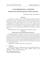
For example, the Furuta pendulum [1] consists of an arm, rotating in the hori-
zontal plane, and a pendulum, attached to the end of the arm. The horizontal
arm is actuated by a DC-motor, but the vertical pendulum is unactuated, and
swings freely in the vertical plane. A Lagrangian analysis leads to the well-known
mathematical description of Furuta pendulum given by
m
p
r
2
+J
b
¨
θ+m
p
r¨αI
p
cos (α)-m
p
r ˙α
2
I
p
sin (α)=u
t
m
p
r
¨
θI
p
cos (α)-m
p
r ˙αI
p
sin (α)+m
p
¨αI
2
p
-m
p
gI
p
sin (α)=0
(39)
where T is the input torque from the DC motor m
p
is the mass of the pendulum,
I
p
is the length from the center of gravity of the pendulum with respect to the
motor axis, J
b
is the moment of inertia of the arm and the gears, θ is the
deflection of the arm from the zero position, α is the deflection of the pendulum
from the vertical upright position and r is the length of the arm (Fig. 1).
The previous mathematical model (39) may be represented in its state variable
form as follows
˙x
1
=˙α=x
2
˙x
2
=¨α=
u
t
+m
p
rx
2
2
I
p
sin (x
1
)
(cos (x
1
) r)-
m
p
r
2
+J
b
(g+rx
2
)sin(x
1
)
I
p
(cos
2
(x
1
) m
p
r
2
) −(m
p
r
2
+ J
b
)(I
p
)
˙x
3
=
˙
θ=x
4
, ˙x
4
=
¨
θ=
1
cos (x
1
) r
((g+rx
2
)sin(x
1
)-Z)
Z=
u
t
+m
p
rx
2
2
I
p
sin (x
1
)
(cos(x
1
) r)-
m
p
r
2
+J
b
(g+rx
2
)sin(x
1
)
cos
2
(x
1
) m
p
r
2
-(m
p
r
2
+J
b
)
(40)
Noticed that just the velocity x
4
is on-line measurable. We apply our approach
to stabilize this manipulator in a fixed position. The DNN observer structure
together with the weights adjustment law lead to an artificial dynamics which is
able to reproduce the nonlinear mechanical system, that has been used just like
a data source. The adaptive observer does not employ the mathematical model
given in (40) at all. As it can be seen from the figure (2) the observation problem
is successfully solved.
In this case ˙x
∗
1
=˙x
∗
2
=˙x
∗
3
=˙x
∗
4
= 0 and the sliding surface is selected as S :=
1
2
x
∗
− ˆx
2
=0,
˙
S =
x
∗
− ˆx
t
,
d
dt
(x
∗
− ˆx
t
)
= 0 which has relative degree one
with respect to the control action. The corresponding super-twisting controller is
given by u
t
= −
⎛
⎝
5
t
τ=0
sign(S)dτ +2S
1/2
sign(S)
⎞
⎠
. This nonlinear controller
High Order Sliding Mode Neurocontrol 193
Fig. 1. The Furuta pendulum
0 20 40 60 80 100 120
−5
0
5
10
Time,s
(a)
Pendulum Possition, rad
DNN x
1,t
Pen. Pos.
0 20 40 60 80 100 120
−5
0
5
Time,s
(b)
Pendulum Velocity, rad/s
DNN x
2,t
Pen. Vel.
0 20 40 60 80 100 120
−2
−1
0
1
2
Time,s
(c)
Arm Possition, rad
DNN x
3,t
Arm. Pos.
0 20 40 60 80 100 120
−4
−2
0
2
4
Time,s
(d)
Arm Velocity, rad/s
DNN x
4,t
Arm Vel.
Fig. 2. The observation results for the Furuta pendulum example
supplies an adaptive signal (depending on the current DNN weights values) to
fulfill the tracking requirements (see Fig. 3).
The correspondence between the trajectories supplied by reference model,
the DNN observer and the Furuta pendulum states demonstrates the benefits
provided by the method suggested in this chapter.
4.2 Water Ozonation Process
Ozone has been often used for the treatment of domestic and industrial wastew-
aters [26]. However, those ozonation applications have been limited by the high
cost of ozone production and the low ozone efficiency due to its poor mass trans-
fer rate [9].
194 I. Chairez, A. Poznyak, and T. Poznyak
0 20 40 60 80 100 120
−5
0
5
10
Time,s
(a)
Pendulum Possition, rad
CDNN x
1,t
*
Pen. Pos.
0 20 40 60 80 100 120
−5
0
5
Time,s
(b)
Pendulum Velocity, Pen. Vel.
CDNN x
2,t
*
Pen. Vel.
0 20 40 60 80 100 120
−2
−1
0
1
2
Time,s
(c)
Arm Possition, rad
CDNN x
3,t
*
Arm. Pos.
0 20 40 60 80 100 120
−4
−2
0
2
4
Time,s
(d)
Arm Velocity, rad/s
CDNN x
4,t
*
Arm Vel.
Fig. 3. The Furuta pendulum tracking process
First and foremost important problem for effective continuous ozonation
system is related to the on-line control methods application, since the classic
controllers design methods (such as PID) require total knowledge on the vari-
ables involved in ozonation (the actual contaminants concentration value and
the ozone mass transfer characteristics). The on-line concentration sensors for
few contaminants can be applied in water and wastewater treatments. However,
in the case of the complex mixtures in real wastewater treatment, the on-line
measurement of all contaminants is unrealistic due two main facts: a high cost
for that class of sensors and the impossibility to design a particular sensor for
each organic contaminant. Here, the DNN observer seems to be an effective in-
strument to deal with this particular system (organics ozonation). Indeed, in the
case of the residual water treatment by ozone, any mathematical model can not
be directly applied because of the complex organics composition and the effect
related to the combination of two different reaction mechanisms [23] (depending
on the pH value while the reaction occurs): by molecular ozone and by indirect
reactions using the free radicals. The ozonation process for two contaminants
can be described by:
˙x
1,t
=
1
V
gas
(W
gas
(u
t
-x
1,t
)-K
sat
(Q
max
-x
2,t
)+x
2,t
(k
c1
x
3,t
+k
c2
x
4,t
))
˙x
2,t
= K
sat
(Q
max
− x
2,t
) −k
c1
x
2,t
x
3,t
− k
c2
x
2,t
x
4,t
˙x
3,t
= −k
c1
V
−1
liq
x
2,t
x
3,t
, ˙x
4,t
= −k
c2
V
−1
liq
x
2,t
x
4,t
,y
Oz
= x
1,t
(41)
where x
1,t
(mol/l) is the ozone concentration in the output of the reactor (this is
ozone which doesn’t react with organic compounds dissolved in water), x
2,t
(mol)
is ozone dissolved in a liquid phase, x
3,t
(mol/l) is the first organic compound
concentration at time t while x
4,t
(mol/l) is the concentration of the second
contaminant. The parameters involved in the model description, have the fol-
lowing physical meaning: V
gas
=0.4l is the volume of gas phase in the reactor,
High Order Sliding Mode Neurocontrol 195
W
gas
=0.02 l/s is the oxygen gas flow in the inlet of the reactor, K
sat
=0.02
s
−1
is the ozone saturation constant, Q
max
=4· 10
−6
mol is the maximum
of ozone being in the saturated state liquid phase under the given conditions,
k
c1
= 756 l/ (mol ·s) is the ozonation rate constant for the first contaminant and
k
c2
= 1534 l/(mol ·s) is the rate constant for the second compound, V
liq
=0.6l
is the liquid phase volume in the reactor. The state estimates are depicted in
Fig. (4):
0 200 400 600
0
0.02
0.04
0.06
0.08
0.1
Time,s
(a)
Gas Phase Ozone Concentration, mol
/
DNN x
1,t
x
1,t
0 200 400 600
0
0.005
0.01
0.015
0.02
Time,s
(b)
Liquid Phase Ozone, mol
DNN x
2,t
x
2,t
0 200 400 600
0
0.01
0.02
0.03
0.04
Time,s
(b)
First Organic Concentration, mol/L
DNN x
3,t
x
3,t
0 200 400 600
0
0.002
0.004
0.006
0.008
0.01
0.012
Time,s
(b)
Second Organic Concentration, mol/L
DNN x
4,t
x
4,t
Fig. 4. State estimation process for the ozonation problem
The optimization for the ozonation process should be supplied by the adequate
selection of a reference dynamics (15) which reflects a desired performance. This
”optimal reaction” with ozone can be understood as a minimal time of ozonation.
The corresponding reference model is selected as follows:
˙x
∗
1,t
=
1
V
gas
W
gas
C
∗
gas
-x
∗
1,t
-K
sat
Q
∗
max
-x
∗
2,t
+x
∗
2,t
k
∗
c1
x
∗
3,t
+k
∗
c2
x
∗
4,t
˙x
∗
2,t
= K
sat
Q
∗
max
− x
∗
2,t
− k
∗
c1
x
∗
2,t
x
∗
3,t
− k
∗
c2
x
∗
2,t
x
∗
2,t
˙x
∗
3,t
= −k
∗
c1
V
−1
liq
x
∗
2,t
x
∗
3,t
, ˙x
∗
4,t
= −k
∗
c2
V
−1
liq
x
∗
2,t
x
∗
4,t
y
Oz
= x
1,t
K
sat
=0.02s
−1
,V
liq
=0.6l, Q
∗
max
= varies, W
gas
=0.02l/s,
V
gas
=0.4l, k
∗
c1
= 1123l/ (mol · s) ,k
c2
= 1878l/ (mol · s)
The parameter k
∗
c
represents a fictitious increment in the reaction rate con-
stant. These k
∗
ci
(i =1, 2) of the augmented values ({1123, 1878} vs {978, 1534})
represent a reduction on the required time to eliminate the organic compound
considered in the reaction. The sliding surface and the control action were
selected as
S =
1
2
ˆx
t
2
,u
t
= −
⎛
⎝
0.5
t
τ=0
sign(S)dτ +0.3 S
1/2
sign(S)
⎞
⎠
196 I. Chairez, A. Poznyak, and T. Poznyak
0 100 200 300 400 500 600
0
0.005
0.01
0.015
0.02
0.025
0.03
0.035
0.04
Time,s
Organics Concentration, mol/l
CDNN x
3,t
x
*
3,t
CDNN x
4,t
x
*
4,t
Fig. 5. Tracking process for the ozonation problem
The next figures depict the tracking performance where two different signals are
shown: the reference model states (x
∗
t
) and the nonlinear system dynamics (x
t
)
related with the ozonation process. The closeness between two different signals
(see Fig. 5) provides a numerical justification for the suggested method.
References
1.
¨
Astrom, K.J., Furuta, K.: Swinging up a pendulum by energy control. Automat-
ica 36, 287–295 (2000)
2. Bartolini, G., Ferrara, A., Levant, A., Usai, E.: On Second-Order Sliding Mode
Controllers. In: Ozguner, U., Young, K.K.D. (eds.) Variable Structure Systems,
Sliding Mode and Nonlinear Control. Lecture Notes in Control and Information
Sciences, vol. 247. Springer, New York (1999)
3. Bartolini, G., Ferrara, A., Usai, E.: Chattering Avoidance by Second-Order Sliding
Mode Control. IEEE Transactions on Automotic Control 43, 241–246 (1998)
4. Boiko, I.: Exact Periodic Solution for Control System Containing Static Nonlin-
ear Function. In: Proc. VSS 2006 - The 9th International Workshop on Variable
Structure Systems, Alghero, Italy (2006)
5. Filippov, A.: Differential equations with discontinuous right-hand side. Kluwer
Accademic Publishers, Dordrecht (1998)
6. Fridman, L.: An averaging approach to chattering. IEEE Transactions on Auto-
matic Control 46, 1260–1264 (2001)
7. Gao, W., Wang, Y., Homaifa, A.: Discrete-time variable structure control systems.
IEEE Trans. Ind. El. 42, 117–122 (1995)
8. Haykin, S.: Neural Networks. A comprehensive Foundation. IEEE Press, New York
(1994)
9. Hsu, Y.C., Chen, Y.F., Chen, J.H.: Decolorization of dye RB-19 solution in a
continuous ozone process. J. Environ. Sci. Heal. 39, 127–144 (2004)
10. Isidori, A.: Nonlinear Control Systems, 2nd edn. Springer, New York (1989)
High Order Sliding Mode Neurocontrol 197
11. Khan, M.K., Spurgeon, S.K., Levant, A.: Simple output-feedback 2-sliding con-
troller for systems of relative degree two. In: Proc. 2003 European Control Confer-
ence, Cambridge, UK (2003)
12. Kurkova, V.: Kolmogorv’s theorem and multilayer neural networks. Neural Net-
works 5, 501–506 (1992)
13. Levant, A.: Sliding order and sliding accuracy in sliding mode control. International
Journal of Control 58, 1247–1263 (1993)
14. Levant, A.: Robust exact differentiation via sliding mode technique. Automatica 34,
379–384 (1998)
15. Levant, A.: Universal Single-InputSingle-Output (SISO) Sliding-Mode Controllers
With Finite-Time Convergence. IEEE Transactions on Automatic Control 46,
1447–1451 (2001)
16. Levant, A.: Higher-order sliding modes, differentiation and output feedback control.
International Journal of Control 76, 924–941 (2003)
17. Lewis, F.L., Yesildirek, A., Liu, K.: Multilayer neural-net robot controller with
guaranteed tracking performance. IEEE Trans. Neural Netw. 7, 1–11 (1996)
18. Ljung, L.: System Identification, Theory for the user. Springer, Berlin (1979)
19. Narendra, K., Parthasarathy, K.: Identification and control of dynamical systems
using neural networks. IEEE Trans. Neural Netw. 1, 4–27 (1990)
20. Poznyak, A.: Deterministic Output Noise Effects in Sliding Mode Observation. In:
Sabanovic, A., Fridman, L., Spurgeon, S. (eds.) Variable Structure Systems: From
Principles to Implementation. IET Press, London (2001)
21. Poznyak, A., Sanchez, E., Yu, W.: Differential Neural Networks for Robust Non-
linear Control (Identification, state estimation and trajectory tracking). World
Scientific, Singapore (2001)
22. Poznyak, A., Shteesel, Y., Jimenez, C.: Min-Max Sliding-Mode Control for Multi-
model linear Time varying Systems. IEEE Transactions on Automatic Control 48,
2141–2150 (2003)
23. Poznyak, T., Chairez, I., Poznyak, A.: Application of a neural observer to phe-
nols ozonation in water. Simulation and kinetic parameters identification. Water
Research 39, 2611–2620 (2005)
24. Poznyak, A., Yu, W., Sira-Ramirez, H., Sanchez, E.: Robust Identification by Dy-
namic Neural Networks Using Slinding Mode Learning. Applied Mathematics and
Computer Sciences 8, 101–110 (1998)
25. Prolla, J.P.: On the Weierstrass-Stone theorem. Journal of approximation the-
ory 78, 299–313 (1994)
26. Rice, R.: Applications of ozone for industrial wastewater treatment, a review.
Ozone Sci. Eng. 18, 477–515 (1997)
27. Rovithakis, G., Christodoulou, M.: Adaptive control of unknown plants using dy-
namical neural networks. IEEE Trans. Syst. Man Cyb. 24, 400–412 (1994)
28. Sanchez, E., Loukianov, A., Felix, R.A.: Recurrent neural block form controller.
Automatica 39, 1275–1282 (2003)
29. Utkin, V.I.: Variable strcuture systems: present and future. Automation and re-
mote control 44, 1105–1120 (1983)
30. Utkin, V.I., Guldner, J., Shi, J.: Sliding Modes in Electromechanical Systems.
Taylor and Francis, London (1999)
31. Zak, H., Walcott, B.: State observation of nonlinear control systems via the method
of Lyapunov. In: ZInober, A. (ed.) Deterministic Control of Uncertain Systems.
Lecture Notes in Control and Information Sciences. Springer, Berlin (1990)
198 I. Chairez, A. Poznyak, and T. Poznyak
ProofofTheorem1.Define the state estimation error as Δ
t
= x
t
−ˆx
t
and the
output error as e
t
= y
t
−ˆy
t
= Cx
t
+ξ
2,t
−C ˆx
t
= CΔ
t
+ξ
2,t
for which the following
identities hold: C
e
t
= N
−1
δ
Δ
t
+ C
ξ
2,t
-δΔ
t
,Δ
t
= N
δ
C
e
t
-C
ξ
2,t
+δΔ
t
.The
dynamics of Δ
t
is governed by the following ODE:
˙
Δ
t
=˙x
t
−
dˆx
t
dt
= AΔ
t
+
˜
W
1,t
σ (ˆx
t
)+W
∗
1
˜σ (x, ˆx
t
)+
˜
W
2,t
ϕ (ˆx) u
t
−
W
∗
2
˜ϕ (x, ˆx
t
) u +
˜
f
t
+ ξ
1,t
− K
1
(y
t
− ˆy
t
) −K
2
y
t
− Cˆx
t
y
t
− Cˆx
t
(42)
where ˜σ
t
:= σ (x
t
) − σ (ˆx
t
)and˜ϕ (x, ˆx
t
)=ϕ (x) − ϕ (ˆx
t
). Define the following
Lyapunov-like (energetic) function as (i =1,2,κ>0):
V := V
Δ, ˆx,
˜
W,t
= Δ
t
2
P
1
+ ˆx
t
2
P
2
+
2
−1
k
−1
1,t
tr
˜
W
1,t
˜
W
1,t
+2
−1
k
−1
2,t
tr
˜
W
2,t
˜
W
2,t
+κ
˜
W
2,t
ϕ (ˆx)
2
+ λ
−1
(43)
which time derivative is
˙
V = Δ
t
P
1
˙
Δ
t
+2ˆx
t
P
2
d
dt
ˆx
t
+tr
k
−1
1,t
˜
W
1,t
−2
−1
k
−1
1,t
˙
k
1,t
˜
W
1,t
+
˙
W
1,t
+tr
k
−1
2,t
˜
W
2,t
−2
−1
k
−1
2,t
˙
k
2,t
˜
W
2,t
+
˙
W
2,t
−
2κ
˜
W
2,t
ϕ (ˆx)
2
+ λ
−2
˜
W
2,t
ϕ (ˆx) ,
d
dt
˜
W
2,t
ϕ (ˆx)+
˜
W
2,t
˙ϕ (ˆx)
(44)
Notice that Δ
t
P
1
AΔ
t
=
1
2
Δ
t
[P
1
A + A
P
1
] Δ
t
and estimating the rest of the
terms in (42) using the matrix inequality XY
+ YX
≤ XΛX
+ YΛ
−1
Y
valid for any X, Y ∈ R
r×s
and any 0 <Λ= Λ
∈ R
s×s
one gets:
2Δ
t
P
1
˙
Δ
t
≤ Δ
t
δ
2
Λ
−1
1
+δ
2
Λ
−1
2
+2
˜
f
1
Λ
¯
f
+λ
max
(Λ
σ
) l
σ
Δ
t
+
Δ
t
P
1
W
∗
1
Λ
−1
σ
(W
∗
1
)
+W
∗
2
Λ
−1
ϕ
(W
∗
2
)
+Λ
−1
f
+Λ
−1
ξ
1
P
1
Δ
t
+2Υ
2
+
˜
f
0
+Υ
1
+2
˜
f
1
ˆx
t
2
Λ
¯
f
+
˜
f
2
ˆx
2
Λ
˜
f
+e
t
CN
δ
P
1
˜
W
1,t
σ (ˆx
t
)+
Δ
t
[P
1
A+A
P
1
] Δ
t
+σ
(ˆx
t
)
˜
W
1,t
P
1
N
δ
C
Λ
−1
ξ
2
C+Λ
1
N
δ
P
1
˜
W
1,t
σ (ˆx
t
)+
e
t
CN
δ
P
1
˜
W
2,t
ϕ (ˆx) u
t
+u
t
ϕ
(ˆx)
˜
W
2,t
P
1
N
δ
C
Λ
−1
ξ
2
C+Λ
2
N
δ
P
1
˜
W
2,t
ϕ (ˆx) u
t
+ ˜ϕ (x, ˆx
t
) u
2
Λ
ϕ
-Δ
t
P
1
K
1
(y
t
− ˆy
t
)-Δ
t
P
1
K
2
y
t
− Cˆx
t
y
t
− Cˆx
t
By the same reason, it follows 2Δ
t
P
1
K
1
(y
t
-ˆy
t
) ≤ Δ
t
[P
1
K
1
C+C
K
1
P
1
] Δ
t
+
Δ
t
P
1
K
1
Λ
−1
ξ
2
K
1
P
1
Δ
t
+ Υ
2
and, in view of the selection K
2
= kP
−1
1
C
and
by the inequality (19) in [20], one gets
Δ
t
P
1
K
2
CΔ
t
+ ξ
2,t
CΔ
t
+ ξ
2,t
≥ k
√
α
P
1
−
δλ
max
P
−1
1
Δ
t
P
1
− 2k
n
λ
max
Λ
ξ
2
√
Υ
2
. Additionally,
High Order Sliding Mode Neurocontrol 199
2ˆx
t
P
2
Aˆx
t
+ W
1,t
σ (ˆx
t
)+W
2,t
ϕ (ˆx
t
) u
t
+ K
1
[y
t
− Cˆx
t
]+K
2
y
t
− Cˆx
t
y
t
− Cˆx
t
≤ ˆx
t
P
2
A + A
T
P
2
ˆx
t
− ˆx
t
P
2
˜
W
1,t
σ (ˆx
t
) −2ˆx
t
P
2
˜
W
2,t
ϕ (ˆx
t
) u
t
+ˆx
t
P
2
K
1
CΛ
K1
C
+ Λ
−1
ξ
2
K
1
P
2
ˆx
t
+ Δ
t
Λ
−1
K1
Δ
t
+ Υ
2
+ ˜ϕ (x, ˆx
t
) u
2
Λ
ϕ
+
2ˆx
t
P
2
Λ
−1
K2
P
2
ˆx
t
+ k
2
λ
max
CP
−1
1
Λ
−1
K2
P
−1
1
C
+
ˆx
t
W
∗
1
Λ
−1
σ
(W
∗
1
)
+ W
∗
2
Λ
−1
ϕ
(W
∗
2
)
+ λ
max
(Λ
σ
) l
σ
ˆx
t
Using the upper bound u
t
Λ
u
u
t
≤ v
0
+ v
1
ˆx
2
Λ
u
(9), after the substitution of
all of these inequalities in (44) one gets the following:
˙
V ≤ Δ
t
[P
1
(A + K
1
C)+(A + K
1
C)
P
1
] Δ
t
Δ
t
δ
2
Λ
−1
1
+ δ
2
Λ
−1
2
+2
˜
f
1
Λ
¯
f
+ λ
max
(Λ
σ
) l
σ
+ Λ
−1
K1
+ Q
0
Δ
t
+
Δ
t
P
1
W
∗
1
Λ
−1
σ
(W
∗
1
)
+ W
∗
2
Λ
−1
ϕ
(W
∗
2
)
+ Λ
−1
f
+ Λ
−1
ξ
1
+ K
1
Λ
−1
ξ
2
K
1
P
1
Δ
t
+ˆx
t
P
2
A + A
T
P
2
ˆx
t
+ˆx
t
P
2
K
1
CΛ
K1
C
+ Λ
−1
ξ
2
K
1
+2Λ
−1
K2
P
2
ˆx
t
+
ˆx
t
2
˜
f
1
λ
max
Λ
¯
f
+
˜
f
2
λ
max
Λ
˜
f
+2ϕ
+
v
1
Λ
u
ˆx
t
+
ˆx
t
W
∗
1
Λ
−1
σ
(W
∗
1
)
+ W
∗
2
Λ
−1
ϕ
(W
∗
2
)
+ λ
max
(Λ
σ
) l
σ
ˆx
t
4Υ
2
+
˜
f
0
+Υ
1
+2k
√
nλ
−1/2
max
Λ
ξ
2
√
Υ
2
+k
2
λ
max
CP
−1
1
Λ
−1
K2
P
−1
1
C
+2ϕ
+
v
0
−k
√
α
P
1
−
δλ
max
P
−1
1
Δ
t
P
1
−Δ
t
2
Q
0
+
e
t
C + σ
(ˆx
t
)
˜
W
1,t
P
1
N
δ
C
Λ
−1
ξ
2
C + Λ
1
N
δ
P
1
˜
W
1,t
σ (ˆx
t
)+
e
t
C + u
t
ϕ
(ˆx)
˜
W
2,t
P
1
N
δ
C
Λ
−1
ξ
2
C + Λ
2
N
δ
P
1
˜
W
2,t
ϕ (ˆx) u
t
−
2ˆx
t
P
2
˜
W
1,t
σ (ˆx
t
) −2ˆx
t
P
2
˜
W
2,t
ϕ (ˆx
t
) u
t
−
tr
k
−1
1,t
˜
W
1,t
2
−1
k
−1
1,t
˙
k
1,t
˜
W
1,t
-
˙
W
1,t
-tr
k
−1
2,t
˜
W
2,t
2
−1
k
−1
2,t
˙
k
2,t
˜
W
2,t
-
˙
W
2,t
−2κ
˜
W
2,t
ϕ (ˆx)
2
+ λ
−2
˜
W
2,t
ϕ (ˆx) ,
d
dt
˜
W
2,t
ϕ (ˆx)+
˜
W
2,t
˙ϕ (ˆx)
where ϕ
+
= λ
max
[˜ϕ
(x, ˆx
t
) Λ
ϕ
˜ϕ (x, ˆx
t
)]. Since both Riccati equations (17) ad-
mit positive definite solutions, P
1
and P
2
, and under the adaptive weights ad-
justment laws (16), one gets
˙
V ≤ χ (k)-k
√
α
P
1
-
δλ
max
P
−1
1
Δ
t
P
1
-
α
Q
Δ
t
2
P
1
. Integrating both sides and defining α
Q
:= λ
min
P
−1/2
1
Q
0
P
−1/2
1
> 0, we get
lim
T →∞
V
T
-V
0
T
≤ χ (k)+
lim
T →∞
1
T
⎛
⎝
-k
√
α
P
1
-
T
t=0
α
Q
Δ
t
2
P
1
dt+k
δλ
max
P
−1
1
Δ
t
P
1
dt
⎞
⎠
200 I. Chairez, A. Poznyak, and T. Poznyak
Defining β
t
:= lim
T →∞
1
T
T
t=0
Δ
t
P
1
dt and applying the Jensens inequality
T
t=0
Δ
t
2
P
dt ≥
⎛
⎝
T
t=0
Δ
t
P
dt
⎞
⎠
2
the last inequality becomes α
Q
β
2
t
+2k˜αβ
t
− χ (k) ≤ 0, ˜α :=
√
α
P
1
−
δλ
max
P
−1
1
that leads to
β
t
≤
−2k˜α +
[2k˜α]
2
+4α
Q
χ (k)
2α
Q
≤
2χ (k)
2k˜α +
[2k˜α]
2
+4α
Q
χ (k)