Application of multi objective optimisation to MRT systems optimisation
Bạn đang xem bản rút gọn của tài liệu. Xem và tải ngay bản đầy đủ của tài liệu tại đây (624.27 KB, 104 trang )
Founded 1905
APPLICATION OF MULTI-OBJECTIVE
OPTIMISATION TO MRT SYSTEMS
BY
TIAN LIFEN
DEPARTMENT OF ELECTRICAL ENGINEERING
A THESIS SUBMITTED
IN PARTIAL FULFILLMENT OF THE REQUIREMENT FOR
THE DEGREE OF MASTER OF ENGINEERING
NATIONAL UNIVERSITY OF SINGAPORE
2004
Acknowledgements
Acknowledgements
The author genuinely appreciates the help from her supervisor, Professor C. S. Chang,
who has provided invaluable guidance to the author while the author works on the
projects and writes this thesis.
Sincere thanks and gratitude are also extended to Mr. Seow Hung Cheng of Power
System laboratory for his support throughout this research project.
This thesis is dedicated to the author’s family and friends. They always have the
unreserved understanding and great support to the author.
I
Table of Contents
Table of Contents
ACKNOWLEDGEMENTS .....................................................................................................................I
TABLE OF CONTENTS ....................................................................................................................... II
LIST OF FIGURES ................................................................................................................................ V
LIST OF TABLES ................................................................................................................................. VI
LIST OF ABBREVIATIONS ............................................................................................................. VII
LIST OF PUBLICATIONS RELATED TO THIS THESIS...........................................................VIII
SUMMARY OF THE THESIS............................................................................................................. IX
CHAPTER 1 INTRODUCTION ............................................................................................................ 1
1.1 BACKGROUND ................................................................................................................................. 1
1.2 MOTIVATION OF THE RESEARCH...................................................................................................... 2
1.2.1 Go-Circuit Optimisation ......................................................................................................... 3
1.2.2 Return-Circuit Optimisation ................................................................................................... 4
1.3 OBJECTIVE AND SCOPE OF THE RESEARCH ...................................................................................... 5
1.4 MULTI-OBJECTIVE OPTIMISATION ALGORITHMS............................................................................. 6
1.5 ORGANISATION OF THE THESIS ........................................................................................................ 8
CHAPTER 2 OUTLINE OF GO-CIRCUIT OPTIMISATION ........................................................ 11
2.1 INTRODUCTION .............................................................................................................................. 11
2.2 MATHEMATICAL MODEL ............................................................................................................... 12
2.2.1 System Model ........................................................................................................................ 12
2.2.2 Objective Functions............................................................................................................... 13
2.2.3 Impact of Operational Timetable .......................................................................................... 15
2.3 LAYOUT OF THREE-STAGE SCHEME .............................................................................................. 16
2.4 SIMULATION OUTLINE ................................................................................................................... 18
2.5 SUMMARY ..................................................................................................................................... 19
CHAPTER 3 OUTLINE OF RETURN-CIRCUIT OPTIMISATION ............................................. 21
3.1 INTRODUCTION .............................................................................................................................. 21
3.2 MATHEMATICAL MODEL ............................................................................................................... 22
3.2.1 Return-Circuit Model ............................................................................................................ 22
3.2.2 Objective Functions............................................................................................................... 23
3.2.3 Impact of Earthing and Bonding Arrangements.................................................................... 24
3.3 LAYOUT OF TWO-STAGE SCHEME ................................................................................................. 25
3.4 SIMULATION OUTLINE ................................................................................................................... 27
3.5 SUMMARY ..................................................................................................................................... 28
II
Table of Contents
CHAPTER 4 LITERATURE REVIEW OF MULTI-OBJECTIVE OPTIMISATION
APPROACHES...................................................................................................................................... 30
4.1 INTRODUCTION .............................................................................................................................. 30
4.2 MATHEMATICAL DEFINITION......................................................................................................... 30
4.3 PREFERENCE STRUCTURE .............................................................................................................. 32
4.4 REVIEW OF MULTI-OBJECTIVE OPTIMISATION METHODS ............................................................. 33
4.4.1 Traditional Approaches......................................................................................................... 34
4.4.2 Evolutionary Approaches...................................................................................................... 35
4.4.2.1 Vector Evaluated Genetic Algorithm..............................................................................................35
4.4.2.2 Pareto-Based Genetic Algorithm ....................................................................................................36
4.4.2.3 Multi-Attribute Genetic Algorithm.................................................................................................37
4.4.3 Discussions............................................................................................................................ 37
4.5 SUMMARY ..................................................................................................................................... 39
CHAPTER 5 EVOLUTIONARY MULTI-OBJECTIVE OPTIMISATION APPROACHES....... 40
5.1 INTRODUCTION .............................................................................................................................. 40
5.2 MULTI-OBJECTIVE GENETIC ALGORITHM ..................................................................................... 41
5.2.1 Selection Processing with Rank Assignment ......................................................................... 41
5.2.2 Fitness Sharing...................................................................................................................... 42
5.2.3 Variable Recombination Operators ...................................................................................... 43
5.2.4 Treatment of Preferred Priorities among Objectives ............................................................ 43
5.3 MULTI-OBJECTIVE PARTICLE SWARM ALGORITHM ....................................................................... 45
5.3.1 Search Strategy ..................................................................................................................... 45
5.3.2 Rank-Based Selection ............................................................................................................ 47
5.3.3 Weight Update....................................................................................................................... 47
5.3.4 Pareto-Optimal Set Update ................................................................................................... 48
5.4 MULTI-OBJECTIVE DIFFERENTIAL EVOLUTION ALGORITHM ......................................................... 49
5.5 SUMMARY ..................................................................................................................................... 49
CHAPTER 6 RESULTS OF GO-CIRCUIT OPTIMISATION ........................................................ 50
6.1 OPTIMAL TRACTION-SUBSTATION PLACEMENTS ........................................................................... 50
6.2 WORST-CASE SCENARIOS OF OPERATIONAL DEVIATIONS ............................................................. 53
6.3 PERFORMANCE CHECK FOR FAILURE CONDITIONS ........................................................................ 56
6.4 SUMMARY ..................................................................................................................................... 58
CHAPTER 7 RESULTS OF RETURN-CIRCUIT OPTIMISATION.............................................. 60
7.1 MULTI-OBJECTIVE OPTIMISATION FOR NORMAL CONDITIONS ...................................................... 60
7.2 PERFORMANCE CHECK FOR FAILURE CONDITIONS ........................................................................ 68
III
Table of Contents
7.3 SUMMARY ..................................................................................................................................... 69
CHAPTER 8 CONCLUSIONS............................................................................................................. 71
8.1 SUMMARY AND CONCLUSIONS ...................................................................................................... 71
8.2 SUGGESTIONS FOR FUTURE WORK ................................................................................................ 74
REFERENCES ...................................................................................................................................... 75
APPENDIX A EVOLUTIONARY ALGORITHMS .......................................................................... 79
A.1 INTRODUCTION ............................................................................................................................. 79
A.2 GENETIC ALGORITHM ................................................................................................................... 79
A.3 PARTICLE SWARM AND DIFFERENTIAL EVOLUTION ALGORITHM ................................................. 80
A.3.1 Particle Swarm Algorithm .................................................................................................... 81
A.3.2 Differential Evolution Algorithm .......................................................................................... 82
APPENDIX B FLOWCHART OF PROPOSED EVOLUTIONARY MULTI-OBJECTIVE
OPTIMISATION APPROACHES....................................................................................................... 84
B.1 FLOWCHART OF MULTI-OBJECTIVE GENETIC ALGORITHM ........................................................... 84
B.2 FLOWCHART OF MULTI-OBJECTIVE PARTICLE SWARM AND MULTI-OBJECTIVE DIFFERENTIAL
EVOLUTION ......................................................................................................................................... 85
APPENDIX C PRELIMINARY TESTING OF MULTI-OBJECTIVE OPTIMISATION
ALGORITHMS ..................................................................................................................................... 86
C.1 INTRODUCTION ............................................................................................................................. 86
C.2 CONCAVE PROBLEM ...................................................................................................................... 87
C.3 DISCONTINUOUS PROBLEM ........................................................................................................... 89
C.4 SUMMARY ..................................................................................................................................... 91
IV
List of Figures
List of Figures
Figure 1-1: Schematic of Singapore MRT system........................................................1
Figure 2-1: Sectional network representation of double-track MRT system ...............13
Figure 2-2: Three-stage scheme for go-circuit optimisation .......................................18
Figure 2-3: Flowchart for go-circuit simulation .........................................................19
Figure 3-1: Return-circuit model ...............................................................................22
Figure 3-2: Simple case study of touch voltage and stray current ...............................25
Figure 3-3: Two-stage procedure for touch voltage and stray current .........................27
Figure 3-4: Flowchart of return-circuit simulation .....................................................28
Figure 4-1: Pareto front for bi-criterion minimisation problem...................................32
Figure 4-2: Nonconvex solution boundary.................................................................35
Figure 4-3: Outline of VEGA evolution results..........................................................36
Figure 4-4: Rank assignment for Pareto-based genetic algorithm...............................37
Figure 5-1: Rank assignments for different priorities among objectives .....................44
Figure 6-1: Optimised configurations ........................................................................51
Figure 6-2: Energy consumption convergence curve..................................................52
Figure 6-3: Load sharing convergence curve .............................................................52
Figure 6-4: Pareto-optimal set for Configuration 1.....................................................54
Figure 6-5: Pareto-optimal set for Configuration 2.....................................................55
Figure 7-1: Layout of study system............................................................................61
Figure 7-2: Touch voltage distribution with different earthing arrangement ...............63
Figure 7-3: Pareto-optimal sets for Configuration 1 ...................................................65
Figure 7-4: Pareto-optimal sets for Configuration 2 ...................................................66
Figure C-1: MOPS results for Test1 ..........................................................................89
Figure C-2: MODE results for Test 1.........................................................................89
Figure C-3: MOPS results for Test 2 .........................................................................91
Figure C-4: MODE results for Test 2.........................................................................91
V
List of Tables
List of Tables
Table 6-1: Improvement of optimised energy consumption and load sharing .............53
Table 6-2: Parameter limits for bi-criterion optimisation............................................54
Table 6-3: Maximum deviation for energy consumption............................................55
Table 6-4: Maximum deviation for load sharing ........................................................55
Table 6-5: Performance check results for case 1.1 .....................................................57
Table 6-6: Performance check results for case 2.2 .....................................................58
Table 7-1: Typical arrangements of earthing and bonding..........................................62
Table 7-2: Multi-objective optimisation of earthing & bonding for configuration 1 ...67
Table 7-3: Multi-objective optimisation of earthing & bonding for configuration 2 ...68
Table 7-4: Performance check for case 2.1 ................................................................69
Table C-1: Non-dominated solution numbers for Test 1.............................................88
Table C-2: Non-dominated solution numbers for Test 2.............................................90
VI
List of Abbreviations
List of Abbreviations
TSS: Traction Substation
GA: Genetic Algorithm
DE: Differential Evolution algorithm
PS: Particle Swarm algorithm
MOGA: Multi-Objective Genetic Algorithm
MODE: Multi-Objective Differential Evolution algorithm
MOPS: Multi-Objective Particle Swarm algorithm
VII
List of Publications Related to this Thesis
List of Publications Related to this Thesis
[1]
C.S. Chang and L. Tian,” Worst-case identification of touch voltage and stray
current of DC railway system using genetic algorithm”, IEE Proceedings,
Electric Power Applications, Vol. 146, No. 5, 1999
VIII
Summary of the Thesis
Summary of the Thesis
MRT system design can be formulated as a problem of three-stage optimisation. In the
first stage, the basic design of a MRT section is optimised by extensively searching
through a large set of design alternatives. Only the key or primary variables are
optimised in this stage. The second stage evaluates the worst-case performance of the
basic design using secondary variables arising from operational deviations and other
random variables. The need for changing the basic design to cater for both the normal
condition and failure conditions is ascertained and implemented in the third stage.
MRT supply networks can be divided into the traction substation, the go-circuit and
the return-circuit. At traction substations, AC supply voltage is stepped down and
converted to DC. Catenary wires or third rails are used in the go-circuit while running
rails and return cables are the main components of return-circuit. In this work, the gocircuit and return-circuit are each optimised with the procedure as outlined above.
Energy consumption and load sharing are two important issues in the go-circuit.
Energy consumption calculates the total energy consumed at all the traction
substations, and load sharing measures the load distribution among all traction
substations. They are influenced by many factors and their optimisation cannot be
obtained simultaneously. In the proposed first-stage optimisation, a previously
developed algorithm is incorporated for configuring the traction placements by
optimising either energy consumption or load sharing. During operation, train
timetables deviate continually from the predefined train despatch frequency due to
variations of train headway, synchronisation delay and dwell time. This work focuses
IX
Summary of the Thesis
on the second-stage optimisation, which implements the bi-criterion optimisation of
energy consumption and load sharing under normal condition. The system
performance is evaluated under failure conditions in the third stage.
With running rails used as part of the traction current return-circuit, the main concerns
in the return-circuit are the touch voltage and stray current. Touch voltage is the
voltage between the running rail and the ground. Excessive instantaneous touch
voltage jeopardises safety. Stray current is the leakage current between the running rail
and the ground. The stray current is likely to be picked up by the underground
structures in the vicinity and cumulative stray current may accelerate their corrosion.
The earthing and bonding strategy within the system has a profound impact on the
control of touch voltage and stray current. Meanwhile, the improvement of touch
voltage or stray current tends to deteriorate the other. The return-circuit optimisation is
thus composed of two-stage implementation. In the first stage, different earthing and
bonding arrangements at passenger stations or traction substations are extensively
explored under normal operation. The second stage conducts performance check on
each appropriate earthing and bonding arrangement with the list of credible failure
conditions such as rectifiers and inverters out-of-service.
The technique of Pareto-optimal set is developed for the above go-circuit and returncircuit optimisations. The solutions are often multi-objective and seldom unique, as
they usually comprise a finite set of non-dominated or Pareto-optimal points. Three
evolutionary algorithms are applied, which are namely: the Multi-Objective Genetic
Algorithm (MOGA) for discrete problems, Multi-Objective Particle Swarm (MOPS)
algorithm and Multi-Objective Differential Evolution (MODE) algorithm for
X
continuous problems. MOPS and MODE are proposed to solve MRT problems for the
first time.
The three proposed algorithms are based on the concepts of population, rank-based
selection and competitive evolution. During optimisation, a population of candidate
solutions is evolved in the feasible space to search for the Pareto-optimal set. Ranking
of the population is accomplished through Pareto ranking, where all points in the
Pareto-optimal set are successively placed on different Pareto fronts. Competitive
evolution consists of selecting subsets of points with respect to their ranks and moving
them toward the Pareto-optimal set. Test analysis of the proposed algorithms is made
on each of the go-circuit and return-circuit simulations. Numerical comparisons of
MOPS and MODE against the Multi-Attribute Genetic Algorithm (MAGA) favour the
former two algorithms.
XI
Chapter 1 Introduction
Chapter 1 Introduction
1.1 Background
In recent years, many high performance Mass Rapid Transit (MRT) and Light Rapid
Transit (LRT) systems have been built. They are playing increasingly significant roles
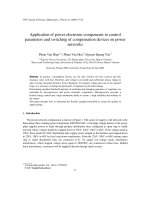
in public transportation. In general, the MRT power supply systems comprise three
parts [10] of traction substation, go-circuit and return circuit as shown in Figure 1-1.
Being focused on the DC transit system, this thesis mainly examines how to achieve
trade-off in the go-circuit and the return-circuit optimisation. The harmonic effects are
not discussed in this thesis, but will be addressed by other researchers [30].
AC Busbar (22kV)
Transformer
Rectifier
Transformer
TSS 1
TSS 2
Inverter
Rectifier
Go-circuit
Go-circuit
Catenary or Third
rail (1500V DC)
Train
Earthing device
Return-circuit
Runnung rail
Earthing device
Figure 1-1: Schematic of Singapore MRT system
1
Chapter 1 Introduction
•
Traction substation: In Singapore MRT system, several traction substations (TSSs)
are located at passenger stations due to construction convenience and cost
consideration. From the viewpoint of electrifying the MRT systems, TSSs function
as energy sources, transferring power between the AC side and the DC side. The
66 kV supply voltage is stepped down to 22 kV at intake substations via the
transformer. Rectifiers installed at TSSs convert power from the 22 kV AC into
DC so as to provide the go-circuit with traction current. While trains are usually
equipped with the regenerative braking, some TSSs are configured with inverters
to increase line receptivity. As a result, power released during regenerative braking
is either consumed by nearby accelerating trains or returned to supply through
inverters. The 22 kV AC is also stepped down to furnish service loads, such as
lighting, air-conditioning and other auxiliary devices at passenger stations.
•
Go-circuit: This contains the catenary wires or third rails and positive feeders. In
most MRT systems, running rails are used as traction return paths. Hence the
traction current, distributed from the TSSs, flows along the catenary wires or third
rails to supply trains with power and then flows back to the TSSs through the
running rails.
•
Return-circuit: Running rails, rail bonds and negative feeders are the main
components of the return-circuit. Running rails are often lightly insulated from the
ground so a fraction of the traction currents may leak into the earth whereas the
bulk of traction currents return to the TSSs via the negative feeders.
1.2 Motivation of the Research
2
Chapter 1 Introduction
Single-objective optimisation techniques have long been applied in MRT system.
Nevertheless, there are needs for multi-objective optimisation. Energy consumption
and load sharing in go-circuit, influenced by many aspects, cannot be optimised
simultaneously. Likewise, the mitigation of touch voltage and stray current in returncircuit are not likely to be achieved at the same time. Practical solutions for multiobjective optimisation are seldom unique, as they comprise a finite set of nondominated or Pareto-optimal points. In this thesis, the technique of Pareto-optimal set
(Section 4.2) is developed for the go-circuit and return-circuit optimisations in MRT
system. Three evolutionary algorithms are explored, namely: the Multi-Objective
Genetic Algorithm (MOGA, Section 5.2) for return-circuit optimisation, MultiObjective Particle Swarm (MOPS) algorithm (Section 5.3) and Multi-Objective
Differential Evolution (MODE) algorithm (Section 5.4) for go-circuit optimisation.
MOPS and MODE are proposed to solve MRT problems for the first time.
1.2.1 Go-Circuit Optimisation
In MRT systems, TSSs supply train power via the rectifiers and receive the
regenerated power via the inverter. The energy consumption, which is calculated as the
sum of the power flowing through the rectifiers and the inverters installed at each TSS,
is quite crucial to the efficiency of the MRT system. In addition to energy flows
through rectifiers and inverters, load sharing among TSSs is also of importance. As
trainloads are highly fluctuating, the TSS loads can be unevenly distributed. Some
TSSs are overloaded but others are under-loaded. In case of some traction substations
outage, the power flowing through the nearby traction substations could exceed their
3
Chapter 1 Introduction
capacity. Therefore, energy consumption and load sharing are selected as optimisation
objectives in go-circuit optimisation.
Energy consumption and load sharing are dependent on the instantaneous train
positions and control status (accelerating, coasting, dwelling or braking). These are
influenced by the service schedule (declared train despatch frequency or headway) and
operational deviations (synchronisation delay and train dwell times). Traction
substation placements also have profound impact on the energy consumption and load
sharing.
At the first stage of go-circuit optimisation, a previously developed algorithm [3] is
incorporated to configure the traction substation placements by optimising either
energy consumption or load sharing. Energy consumption and load sharing are not
consistent with each other. The same train running timetable will probably lead to their
different regulation direction. At the second stage, the effect of operational timetable is
discussed, and the competing nature of energy consumption and load sharing is
investigated. The optimisation variables, namely headway, synchronisation delay and
dwell times, vary continually during the simulation period. In order to solve this
continuous problem, MOPS and MODE algorithms are proposed and applied for the
first time to generate a variety of Pareto-optimal solutions. The compromise between
worst-case energy consumption and load sharing is then identified for performance
margin specification, which is implemented at the third stage of go-circuit
optimisation.
1.2.2 Return-Circuit Optimisation
4
Chapter 1 Introduction
Running rails are usually used as the traction current return paths. Owing to the rail-toground and rail resistance, there will be a voltage difference caused by the return
current flows from between the rails and the local ground known as touch voltage.
Excessive touch voltages jeopardises safety. As running rails are often lightly
insulated, the traction current flowing back to the substations may partly take the
ground. Known as stray current, it is likely to be picked up by the underground
structures in the vicinity and through the ground to enter another structure before
returning to the TSS. Accumulative stray currents may accelerate the structures’
corrosion. Accurate evaluation and effective control of touch voltage and stray currents
are therefore the consideration factors in the return-circuit.
Simulations and field tests reveal that both touch voltage and stray current are greatly
influenced by the earthing strategy and bonding arrangement adopted in MRT system.
However, the improvement of touch voltage or stray current tends to deteriorate the
other. A two-stage scheme is thus proposed for return-circuit optimisation. At the first
stage, Multi-Objective Genetic Algorithm (MOGA) is developed to extensively
explore earthing and bonding arrangements so that the compromising mitigation of
touch voltage and stray current is obtained under normal running condition. At the
second stage, the most appropriate earthing and bonding patterns are then picked up
for performance check under credible failure conditions.
1.3 Objective and Scope of the Research
MRT systems are complex and highly integrated. The scope of this research is
confined to the electrification subsystem and focused on the DC side. In particular,
5
Chapter 1 Introduction
effects of operational parameters rather than design parameters are investigated for the
safety and efficiency of MRT system. Two sets of objectives are defined for the
problem of energy consumption and load sharing in the go-circuit, and the problem of
touch voltage and stray current in the return-circuit. Variables governing these two sets
of objectives can either be discrete or continuous. The nature of competing objectives
in these two problems is explored. Evolutionary algorithms are then applied for
attaining satisfactory trade-offs within these sets of objectives.
Although the use of rectifiers and inverters does introduce harmonic in the MRT
system, harmonic can be minimized by employing appropriate type of power
converters and by placing active harmonic filters [29]. This thesis focuses on the
application of multi-objective optimization of primary variables to MRT systems. The
harmonic effects on go-circuit and return-circuit optimisation are not addressed in this
thesis, but will be discussed by other researchers [30].
1.4 Multi-Objective Optimisation Algorithms
Multi-objective optimisation problems involve in simultaneous optimisation of
multiple non-commensurable objectives. The solution to such problems is not unique
but a family of non-dominated points (Pareto-optimal set). In traditional methods of
multi-objective optimisation, different criteria are linearly blended into a composite
scalar objective. This requires pre-establishment of the weights of different criteria. As
it is never a simple task to specify an appropriate set of weights, optimal solutions are
individually obtained for a range of weights and the so-called trade-off curves are
6
Chapter 1 Introduction
generated [5]. The computing time required for generating the trade-off curves is high
and it is also difficult to apply such techniques to non-convex problems.
The need for an improved multi-objective optimisation method to seek the Paretooptimal solutions is evident, and such a method should have the following
characteristics [23]:
•
Efficiency: It can approximate or identify the entire global Pareto-optimal set
through a one-time solution of the multi-objective optimisation problem, avoiding
the need to solve a multitude of single-objective optimisation problems.
•
Objectivity: It does not require the priori assessment of preferences to objective
functions in the generation of the Pareto-optimal set.
•
Reliability: It can facilitate the evaluation of candidate non-dominated solutions in
a quick and reliable fashion.
The search processes of evolutionary algorithms, using a population of candidates,
suggest their application to multi-objective optimisation problems for finding a number
of Pareto-optimal solutions in parallel. In this thesis, Genetic Algorithm (GA), Particle
Swarm (PS) algorithm and Differential Evolution (DE) algorithm are appropriately
refined for multi-objective optimisation.
The performance of GA is mostly determined by its selection operation. In order to
deal with multiple conflicting objectives, a degree of control should be exerted over
the selection process. With the employment of rank assignment method [16], MOGA
selects individuals for survival according to their mutual dominance as well as their
fitness values. It attempts to trace all the non-dominance individuals in the present
7
Chapter 1 Introduction
population as far as possible and each objective function is utilised separately rather
than collectively. When all the non-dominated individuals in the current generation are
picked, the recombination operators are then applied to produce the next generation.
The above procedure is iterated to locate the Pareto-optimal points and produce
subsequent populations until convergence is met. At the end of MOGA evolution, the
final non-dominated set represents the collection of compromising solutions among all
the objectives.
Encoding brittleness in GA has degraded its performance in continuous problem
domain. Contrary to GA, MOPS and MODE avoid parameter encoding and work
directly on real-value parameter vectors to search for the optimal solutions. The
concept of scalarising function is also introduced to replace the global and individual
best solutions with compromise solutions respectively. The behaviour of each
individual in the population is influenced not only by its own historical performance
but also by its peers. Moreover, rank-based selection is applied in MOPS and MODE
to determine the individual’s likelihood of producing offspring and distribute the
population towards the promising areas.
By modifying the individuals’ ranks, the specification of preferences among objectives
is allowed in MOGA, MOPS and MODE. The technique of fitness sharing is adopted
to maintain the population diversity. With the treatment of dominance properties
among individuals, these evolutionary algorithms possess a more exploitative
mechanism to obtain the Pareto-optimal set.
1.5 Organisation of the Thesis
8
Chapter 1 Introduction
This thesis is organised as follows:
•
Chapter 1 describes briefly the background and the objective of the research. Two
kinds of multi-objective problems, i.e., touch voltage versus stray current (discrete
problem) and energy consumption versus load sharing (continuous problem) are
introduced by outlining their corresponding optimisation approaches.
•
Chapter 2 defines the energy consumption and load sharing in go-circuit. After
presenting the DC-powered two-track MRT system model, this chapter formulates
a three-stage scheme for optimising energy consumption and load sharing and
checking system performance.
•
Chapter 3 defines the touch voltage and stray current in return-circuit. The
concepts of return-circuit modelling and load referral solution method are
explained. A two-stage scheme is also put forward to attain the trade-off between
touch voltage and stray current, and to evaluate the system performance under
failure conditions.
•
Chapter 4 categorises multi-objective optimisation methods and identifies their
specific advantages and disadvantages.
•
Chapter 5 develops a Pareto-based multi-objective genetic algorithm. A particle
swarm algorithm based as well as a differential evolution based multi-objective
optimisation approach is also proposed for the first time to solve the continuous
problems.
•
Chapter 6 discusses mainly the impact of actual operational timetable on energy
consumption and load sharing calculation. The traction substation placements are
9
Chapter 1 Introduction
first configured by obtaining either minimal load sharing or equal load sharing.
Then the proposed continuous multi-objective optimisation methods are applied to
explore the compromise nature of energy consumption and load sharing against
varying operational timetable. Simulation results indicate the effectiveness of the
proposed three-stage scheme for fulfilling the design objective.
•
Chapter 7 discusses the influence of earthing and bonding policies, and, employs
the proposed discrete multi-objective algorithm to achieve trade-off between the
touch voltage and the stray current. The priority assigned to different objectives
allows the decision-maker’s preference to be attained during optimisation.
Simulation results for different earthing and bonding arrangements are compared
and the promising solutions are further checked under failure conditions.
•
Chapter 8 summarises the research with final conclusion and some suggestions for
future work.
10
Chapter 2 Outline of Go-Circuit Optimisation
Chapter 2 Outline of Go-Circuit Optimisation
2.1 Introduction
Energy consumption by TSSs and load sharing among TSSs in go-circuit are
influenced by diverse factors such as station spacing, service schedule, firing angles of
rectifiers and inverters, and transformer tap positions. The impact of traction substation
placements and firing angles of rectifiers and inverters were investigated in [3,5]. In
[3], the energy consumption and load sharing were treated as two separate objective
functions, and Tabu Search (TS) algorithm was applied to explore different
combinations of traction substation placements. For simplicity of optimisation, the
energy consumption and load sharing were combined linearly in [5] to form a single
objective. The conventional Genetic Algorithm (GA) was then employed to examine
the effect of firing angles of rectifiers and inverters. The performance curves were
plotted against the objective weights reflecting the relative significance among
objectives, and the so-called trade-off was made between energy consumption and load
sharing.
The competing nature between energy consumption and load sharing is not fully
discussed in the above work. The traction substation placements and train operational
timetable have great influence on the MRT system, which runs under normal
conditions or failure conditions. Therefore, the go-circuit optimisation in this thesis
presents normal and failure conditions, and is carried out in three stages. Stage I uses
the algorithm of [3] to optimise the traction substation placements, so that minimum
11
Chapter 2 Outline of Go-Circuit Optimisation
energy consumption or equal load sharing is attained. At Stage II, the train operational
timetable varies continuously. Two novel multi-objective optimisation methods
(Multi-Objective Particle Swarm and Multi-Objective Differential Evolution
algorithm) are developed for the first time in this work to obtain the Pareto-optimal set,
and achieve the trade-off between energy consumption and load sharing under normal
running conditions. At Stage III, the worst-case solutions are picked up from Paretooptimal set and the performance check is implemented under failure conditions.
2.2 Mathematical Model
2.2.1 System Model
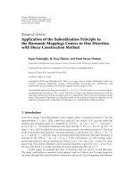
Figure 2-1 schematically shows a two-track DC-powered MRT system. The
components are modelled in terms of resistances and current sources, and the
interconnection of these components constitutes a nodal electrical circuit.
From the viewpoint of circuit theory, the DC-fed MRT system can be divided into gocircuit and return-circuit. In go-circuit, the traction power provided by TSS flows
through the catenary wire or third rail, supplies trains and passes back to TSS via
running rails. TSS is represented by a Thevenin equivalent voltage source (constant
voltage in series with a resistance) or a Norton equivalent current source (constant
current in parallel with a resistance). Trains are modelled as a voltage-dependent
resistance and the running rail is represented by lumped parameters in go-circuit.
The return-circuit deals with the touch voltage and leakage current. Its simulation is
explained in Chapter 3.
12
Chapter 2 Outline of Go-Circuit Optimisation
Negative Busbar
Substation
Positive Busbar
Feeders
Up Track
Catenary or
Third Rail
Train
Rails
Earth
Crossbond
Down Track
Figure 2-1: Sectional network representation of double-track MRT system
2.2.2 Objective Functions
Energy consumption and load sharing are two objective functions in the go-circuit
optimisation.
In order to increase the system receptivity, some of the traction substations (TSSs) are
fitted with inverter to provide stable regenerative braking and transfer the surplus
braking energy to the AC side. That is, TSS supplies trains with nominal DC voltage
(1500 V in Singapore MRT system) via rectifiers, and recovers energy by the use of
inverter. Although the presence of rectifiers and inverters introduces harmonic to MRT
13