lựa chọn sản phẩm cho nhà thông minh smart home
Bạn đang xem bản rút gọn của tài liệu. Xem và tải ngay bản đầy đủ của tài liệu tại đây (3.32 MB, 26 trang )
Selection Of
Products
A how-to technical guide, this
chapter outlines the various
scenarios in which the Siemens
instabus system is used. Features of
the system such as Scene Control,
Motion Detector and Activation
Timer are also touched upon.
Individual products - 5-Step Selection
Selection Of Products:
Individual products:
5-Step Selection Process .......................3-21
-- Select Actuators .................................3-22
-- Select Sensors ....................................3-25
-- Select Controllers ...............................3-28
-- Select System Devices ......................3-29
-- Select Accessories .............................3-31
Features .............................................3-33
-- Scene Control .......................................3-33
-- Infra-Red Handheld
Remote Control ....................................3-35
-- Detachable Switches ..........................3-36
-- Brightness Control ...............................3-36
-- Daylight Control ...................................3-37
-- Motion Detector ..................................3-39
-- Timer ......................................................3-40
-- Time Module .........................................3-41
-- Room Partitioning - Logic Module ....3-42
-- Safety & Security ................................3-43
• Panic Button ......................................3-43
• Smoke/Fire Detector ........................3-43
• Burglar Alarm ....................................3-44
• Presence Simulation ........................3-44
-- Monitoring ............................................3-44
• LCD Display ........................................3-45
• Status Display by PC ........................3-45
• Panel Display .....................................3-46
-- Tele-Control ..........................................3-46
We have separated our products into 5 different categories.
The Actuators switch or control the devices such as lights
when telegrams are received via the bus. The sensors receive
input by way of light sensors, Temperature Sensors, Timers,
manually operated Push Buttons, etc. and convert them into
instabus telegrams. Controllers are needed when special
features are required. For example, logic functions allow 2
different conditions to be fulfilled before an action occurs.
This could be applied in terms of the activation of lamp posts
in Botanic Garden: lights are to be switched on when it hits
6:30pm and the natural light falls below a certain level of
brightness. System Devices such as Power Supplies are
necessities and they need to be incorporated after specifying
the above 3 mentioned devices. Accessories are also necessary
to complete the products. They come in forms of Connectors
and Frames for the Push Buttons.
Hence, the selection process of individual products consists
of five steps:
1. Select Actuators
2. Select Sensors
3. Select Controllers
4. Select System Devices
5. Select Accessories
3-21
Step 1: Select Actuators
Switching
Lighting
Blinds/Curtains
Heater/Air-Con
Other Appliances
The Load determines
the products
Dimming
Bulbs
Halogen Lamps
Florescent Tubes
Conventional Transformer
Electronic Transformer
Actuators are also known as output devices, relays. Actuators are used to switch lights, motors and other
equipment such as heaters, air-conditioners and other appliances via the socket outlets. Most Actuators are
used to do switching, similar to dry contacts, but there are some special Actuators catered for florescent,
halogen lamps dimming and operating motors.
•
•
•
•
Determine the type of load you require
Determine the mounting location
Determine the number of loads
Select the quantity of Actuators
Please refer to the Technical Manual, “Building Management Systems with instabus EIB”, for a more detailed
specification.
Binary Outputs
*UP 560
- Two channel output for ON/OFF switching of two
individual groups. For wall box mounting.
Comes with flat-cable link and connector.
Load ability as other outputs
- IR of 10A per channel at 230V
- Bus-Coupling Unit UP 110 needed. Accessories
such as DELTA frame, cable outlet or blank cover
must be ordered
*AP 600s
- Multi-Channel units with various contact
configurations in IP20 design for optional mounting.
- Load ability of output channels
(please see Binary Outputs)
- Corresponding Plugs must be ordered
*N 560, 561, 562, 566, 510, 512
- Switches external equipment in accord with
telegrams received
- Outputs are free-floating contacts. Various number
of channels with IR of 10A per channel at 230V
except for N510 at IR of 16A and N512 at IR of 20A
each channel
*GE 510, 561, 562, 563
- Switches external equipment in accordance with
telegrams received
- Outputs are free-floating contacts. Various number
of channels with IR, rated current of 10A per channel
at 230V except for the GE 510 at IR of 16A each
channel
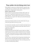
N 510: 4-channel Binary Output
3-22
Step 1: Select Actuators (Cont’d)
Dimmers
*GE 525, 526
- For switching & dimming of florescent lamps with
Siemens ECG Dynamic. One channel per Actuator.
Methods of switching and dimming may be
parameterized
- GE 525 and 526 possess the same properties with
differences in their dimensions.
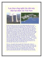
N525: Switching/Dimming Actuator
*N 525
- Switches and dims florescent lamps via control voltage (1 ... 10V) of IR of 16A at 230V. 1 channel only.
- Same properties as GE 525.
To dim florescent lamps (tube-, ring- or compact-form), an electronic dimmable ballast is required to operate
the lamps instead of a conventional or an electronic ballast (non-dimmable). In addition to terminals for the
supply voltage (230V AC), the electronic dimmable ballast has two terminals plus and minus for the control
voltage to dim the lamp (1...10V DC).
The voltage between these two terminals determines the dimming value of the lamp minimum 1V (1%),
maximum 10V (100%).
A relay in the Switching/Dimming Actuator connects and disconnects the electronic Dimmable Ballast from
the supply voltage. Applicable to both GE and N types.
3-23
Step 1: Select Actuators (Cont’d)
Dimmers (Cont'd)
*N 527, 528
- For switching & dimming of halogen lamps. One channel per actuator. Maximum load is either 250 W for
the N528 or 500W for the N527
- Overload protection and short circuit protection incorporated
The Universal Dimmer needs to be connected to a transformer should there be Low-Voltage
Halogen Lamps. Either a conventional or electronic transformer may be used but not a mixture when
connecting them to the same Universal Dimmer.
Drive Control
*N 521
- Two channel output controlling 4 drives. Applications
such as Blinds, Garage doors, Gates etc, OPEN/
CLOSE
- IR of 6A at 230V
*GE 521
- One channel output can control 2 drives in parallel.
Applications such as Blinds, Garage doors, Gates
etc, OPEN/ CLOSE
- IR of 6A at 230V
For Driver Control Actuators, only 1 motor should be connected to each terminal of a channel. For the
GE 521, it has only 1 channel but 2 terminals to operate 2 motors in parallel. For the N521, 2 channels are
made available and allows 4 motors to be connected.
3-24
Step 2: Select Sensors
Devices which serve as inputs to the system are categorized as sensors. These devices send telegrams to
the bus system. Some examples are Push Buttons, Remote Controls, Timers, Motion Detectors, Thermostats,
and so forth. Binary inputs serve as an interface between conventional contacts/switches and control voltages.
• Determine the type of sensors. (Temperature Control, Motion Detectors.... etc.)
• Determine the mounting location
• Determine the number of external signals and quantity of sensors
• Select the sensors.
Please refer to the Technical Manual, “Building Management Systems with instabus EIB”, for a more detailed
specification.
DELTA profil Push Button UP 24x
- Colors: pearl grey
titanium white
anthracite
safari green
taiga beige
sapphire blue
silver
• 1 gang with or w/o symbols
• 2 gang with or w/o symbols
• 4 gang with or w/o symbols
• 4 gang with motion detector
• 4 gang with temperature control
- Direct activation of functions with orientation light
indicating the location of the push button
- Requires UP 110 and respective DELTA profil frames
DELTA ambiente Push Button UP 28x
- Colors: arctic white/ arctic white
arctic white/soft
arctic white/steel
• 1 gang
• 2 gang
• 4 gang
- New touch operational concept where the shape
of the buttons allows identification of the function
by touch
- Requires UP 110 and respective DELTA ambiente
frames
DELTA studio/fläche Push Button UP 21x
- Colors: titanium white
titanium white
light bronze
electric white
slate grey
sand
• 1 gang
• 1 gang
• 2 gang
• 2 gang
• 4 gang
• 4 gang
- Comes in 4 pre-selection buttons with 1 main rocker
for selection and/or basic feature
- Requires UP 110 and respective DELTA studio/fläche
frames
DELTA ambiente
DELTA studio/fläche
3-25
DELTA profil
Step 2: Select Sensors (Cont’d)
Thermostat UP 250/251/252/253
- For temperature controls. Pre-setting of preferred
temperatures 18-20-22oC adjustable by + 2o- 5oC.
Periodic 3oC variation via separate time control
possible
- Requires UP 110 and respective DELTA frames
*DELTA Bus Coupling Unit UP 116
- For interfacing conventional rockers with the
instabus line. DELTA rockers snapped onto DELTA
bus coupling unit
- Available as a push button with neutral position or
toggle push button in 1 or 2 gangs.
- 2 LEDs incorporated to be used as location lighting
or as status display of devices
*Smoke/Fire Sensor AP 256
- Used to detect smoke or fires in buildings or houses.
Smoke and heat alarm signals as well as the actual
temperature are output to instabus
Water Sensor UP 270/271/272
- This can be used to gauge the water level of your
plants, bath, anything you choose. It can be used,
with conjunction of other devices, as a safety device
to close the water valves to prevent over-flowing
- Requires UP 110 and respective DELTA frames
Display Unit UP 580/581/582/583
- LCD Display with a maximum display of 8 messages
with up to 2 x 10 digits freely selectable text.
- Flashing mode and/or acoustic alarm can be activated
- Requires UP 110 and respective DELTA frames
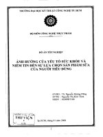
Motion Detector UP 250
- Motion activated but also sensitive to brightness
differences. Contactless devices to sense movement
- Requires UP 110 and DELTA studio frames
Motion Detector
Display Unit
3-26
Step 2: Select Sensors (Cont’d)
Infrared Receiver S 440
- Receives IR signals and converts into electrical
signals which are given onto IR Decoder N450.
Suited for surface or recessed mounting, unit comes
with mounting clip and 1 meter flexible cable.
Maximum permissible cable length to Decoder is
50m.
*4 Channel Binary Inputs GE 2xx
- Adapts up to 4 individual external signals to the
instabus and converts them into telegrams
addressing up to 4 different Actuator groups.
All channel functions are freely parametrizable
In slim-line design for all mountings other than
din-rail mounted snap-on devices
*Infrared Decoder N 450
- Converts receiver signals into 64 different telegrams
thus different Actuators can be addressed.
- Up to 2 Receivers can be connected to 1 Decoder.
*4 Channel Binary Inputs N 2xx
- Adapts up to 4 individual external signals to the
instabus and converts them into telegrams
addressing up to 4 different Actuator groups.
All channel functions are freely parametrizable
- DIN rail mounted
*Brightness Controller GE 252, 253
- For day light controlled operations. Consists of
converter and sensor with 2m flying lead to measure
brightness (lux) of the environment.
- Applications as constant light level controller or
photocell operation by calibration.
*Telecontrol Unit
- Connects instabus to the telephone network.
Electrical loads are switched via the bus through
the telephone network, for e.g., lights, heaters,
event presets.
IR Transmitters AP 420/421/422
- For wireless manual controls of Actuators (via IR
Receiver S440 and IR Decoder N450). Battery
operated (FLAT PAK) for surface mounting or hand
held operation. Rocker operated with center rest
position.
- Transmission range is 8m.
*Push Button Interface UP 220
- Serves as an interface between conventional
switches and instabus. Converts to telegram for
Actuators
- Allows for 4 channels
Handheld Remote Control S 425
- Controls Actuators via bus telegram using IR control
(no wires)
- Transmission range is ~ 20m Batteries required:
4 x 1.5V
IR Transmitters
Push Button Interface UP 220
3-27
IR Handheld Remote Control
Step 3: Select Controllers
Controllers are panel mounted. They offer special features themselves or serve as augmentations to specified
features.
Please refer to the Technical Manual, “Building Management Systems with instabus EIB”, for a more detailed
specification.
*Scene Module N 300
- Preset statuses are called off by telegrams to address designated Actuators involving up to eight group
addresses per memory unit
- Memory capacity per module: four scenes
- By applying two units memory capacity is increased to eight pre-settings
- Actuator designation via application programs
- Scene setting can be changed without the ETS software
*Logic Module N 301
- For forming logic connections “AND” “OR” c/w 8 inputs
- 2 outputs - 8 inputs or 4 outputs - 4 inputs (inversion of outputs possible)
- 4 outputs function designation via application program
*Time Module N 302
- For inverting signals, switch on/off delays, time control for stairway light function.
It has 4 inputs and 4 outputs.
*Brightness Controller Module N 342
- It has 10 independent light controls. It controls interior lights automatically taking into account of the external
brightness
*Event Module N 341
- It is able to store up to 60 programs (scenes) using different combinations of up to 255 devices.
- To use with AP 391 time generator for daily programs and calendar entries. Administers up to 100 calendar
or daily programs
*Operating Hours and Switching Operations Counter N 343
- Used to sense the operating hours via switching operations. Maximum of 36 Sensor/Actuator channel with
1-bit switching objects
*Logic Operation Module N 347
- Allows binary information to be logically combined. Handles up to 255 1-bit communication objects which
can be assigned as the input or output of a logic gate
3-28
Step 4: Select System Devices
System devices are devices found in every project. They are necessities and are mostly found in the distribution
board. Power supplies are necessary to power up the bus and if the power supply does not come with a choke,
the choke must be specified (only applicable for 115V networks). The RS 232 enables programming of the
system via a computer. They are DIN rail mounted or surface mounted.
• Select the System Devices.
• Determine the quantity of Bus Coupling Units (refer to ’Select Actuators‘ and ’Select Sensors‘).
• Select RS 232 interface.
• Calculate the number of programmable devices which are denoted by an asterisk (*).
• Determine the quantity of Power Supply Units and Area/Line Couplers.
Please refer to the Technical Manual, “Building Management Systems with instabus EIB”, for a more detailed
specification.
Power Supply N 123
- Required for every bus line. To be applied with
Choke N120. For 115V with current at 320mA.
RS 232 Interface UP 148
- PC interface, same as N 148. Essential for
programming instabus
- Requires UP 110 and respective DELTA frames
*Area/Line Coupler N 140
- Retains communication within lines not destined
for crossing into other lines. This reduces load of
system considerably
- Operate as:
• area coupler
• line coupler
• line repeater
- In line repeater mode the unit transmits all telegrams
*Bus Coupling Unit UP 110
- For interfacing of Sensors or Actuators with the
instabus line
- For fitting to wall boxes
Choke N 120
- Suited to operate with a maximum of two Power
Supplies N121. Current at 500mA
- With integral reset switch to set all bus devices
into basic mode busline is short circuited and supply
switched ‘OFF’
*RS 232 Interface N 148
- PC interface via Sub D socket 9 pole for addressing,
parameterizing, visualization, protocol and diagnosis
of instabus system
- Essential for programming instabus. DIN rail mounted
Power Supply N 122
- With integral choke and reset switch. For 230V with
output current at 640mA
UP 148 Interface
N 122 Power Supply
3-29
Step 4: Select System Devices (Cont’d)
One power supply is used for every 64 devices. If there are more than 64 devices in an instabus project,
additional Power Supply Units are required. Every Power Supply Unit represents a line. Please refer to figure
below: Line 1, Line 2. In addition, to the Power Supply units, each line must include a Area/Line Coupler. The
main line integrated the individual Line Coupler to one project. This main line requires one more
Power Supply Unit.
Programmable devices are noted by an asterisk (*).
They are defined as:
• Bus Coupling Units (the application unit + the bus coupling units are considered as 1 programmable device)
• DIN rail mounted products except for connectors, power supplies and line couplers
• GE type products
• AP type switching products
Example: Calculation of Power Supply Units and Line Couplers:
DEVICES
GE Type
AP Type
N Type
UP Type
TOTAL
QUANTITY
25
10
30
20
85
DEVICES
GE Type
AP Type
N Type
UP Type
TOTAL
QUANTITY
83
37
213
294
627
85/64 = 1.33 < 2
Therefore:
This project has 2 lines:
2 Power Supply Unit + 1 Power Supply for Main Line
2 Line Couplers
627/64 = 9.80 < 10
Therefore:
This project has 10 lines:
10 Power Supply Unit + 1 Power Supply for Main Line
10 Line Couplers
3-30
The previous example is based on the maximum of 64 devices per line. For new instabus installations,
we recommend not to plan more than 50 devices per line. This is to allow further extension of the system
without having to insert additional System Devices.
Accessories are generally needed for all projects. One example is the Data Rail. For be any DIN rail (N-type)
mounted devices.
Please refer to the Technical Manual, “Building Management Systems with instabus EIB”, for a more detailed
specification.
Step 5: Select Accessories
DELTA Accessories
DELTA studio frames in titanium white, light bronze
or slate grey:
• 1 module
• 2 module
• 3 module
• 4 module
• cable outlet
• blank cover
• 2 module - 1 without cutout, suitable for
conventional rockers (5TG types) and 1 with
cutout, suitable for instabus push buttons
(5WG1 types)
• 3 module - 2 without cutout, suitable for
conventional rockers (5TG types) and 1 with
cutout, suitable for instabus push buttons
(5WG1 types)
DELTA profil frames in pearl grey, titanium white,
anthracite, safari green, taiga beige, sapphire blue or
silver:
• 1 module with cutout, suitable for instabus push
buttons
• 1 module without cutout, suitable for
conventional rockers
• 2 module - both with cutouts, suitable for
instabus push buttons (5WG1 types)
DELTA fläche frames in titanium white, electric white
and sand:
• 1 module
• 2 module
• 3 module
DELTA studio frames
DELTA profil frames
DELTA ambiente frames in arctic white
1 module:
- contour : sharp corners
- convex : rounded corners
DELTA ambiente frames
3-31
DELTA frames Galore
Step 5: Select Accessories (cont’d)
Data Rail 190
Bus connectors 6917/x1, 6918/61
- Required to connect the DIN rail mounted devcies
to the conductor strips for fitting to snap-on rails.
EN 50022 35 x 7.5
- length
214 mm
243 mm
277 mm
- To connect bus cables to the AP 600 devices for
spur-line or loop-through bus line
- Please refer to the Protective Switching and Fuse
Systems catalog
Data Rails are ordered according to the width of the
DIN rail in the Distribution Board. Each Data Rail can
take 12, 14 or 16 modules. The quantity of the
Data Rails depends on 3 factors:
Databus Connectors REG 19x
- To link separate rows of Data Rail or to connect
from 1 distribution board to another.
- To connect the instabus cable by means of Bus
Terminals to the Data Rail
• length of Data Rail
• size of DIN rail products
• quantity of DIN rail products
Example:
Length of DIN rail is 14 modules
1 Power Supply is 7 modules (7 times the width of
a MCB)
1 Scene Module is 1 module
1 Connector is 1 module
Total width is 7 + 1 + 1 = 9 modules.
Bus Terminal 193
- For the connection of instabus cables with instabus
equipment. Thus equipment can be removed
without disrupting the instabus cables. Terminal for
screwless termination of 2 x 4 conductors 0.6 to
0.8 diameter are colour coded
Therefore only one 12MW Data Rail is needed.
Cover Strip 192
Space left on the Data Rail = 12 - 9 = 3
Therefore Cover Strips are needed.
- Separable blank cover strip to insulate & segregate
unused portions of the Data Rail
Plug connector A 6917/x1, A 6918/x1
- An essential connector for AP 600 switching devices
- Please refer to the Protective Switching and Fuse
Systems catalog
3-32
FEATURES
Scene Control
The Scene Modules allow the system to attain a pre-programmed setting with one touch of a button. If Scene
1 is required, simply depress the button labeled Scene 1 for an instant. A telegram will be sent to the Scene
Module to activate Scene 1. One Scene Module offers 4 pre-sets.
Any Push Button may be used to activate the scenes. In the earlier example stated in section: Intelligent Ideas
For Your Project, Scene Control is used in the conference room where Scene 1 is set for a multi-media
presentation and Scene 2 for a slide presentation. The changes are programmed and chosen by the user.
The lights in the front of the room, where the projector is, may be dimmed down and lights at the back of
the room may increase in brightness from Scene 1 to Scene 2. Scene 3 may be set for a speech presentation
where stronger lighting is needed at the spot where the presenter is and Scene 4 may be set to create an
environment suitable for general meeting.
The transition from one scene to another is done just be depressing one button and there is no more hassle
with knobs for the various dimming groups.
3-33
Scene Control (Cont’d)
Scene control offers 2 options due to the difference in methods of presetting the scenes to your liking.
One scene module can program for 4 presets with limited dimming and switching groups.
Option 1
Under option 1, the scenes may be preset with the use of any separate Push Buttons or Infra-Red Remote
Control. One scene module can accommodate up to a maximum of 6 dimming groups or 6 switching groups.
For Option 1, if there are more than the number of groups stated above, additional scene modules are required.
For example, if there are 2 dimming groups and 2 switching group, 2 scene modules are needed. By referring
to the table below, other combinations are shown in relation to the number scene modules required.
Option 1
Option 2
Under option 2, the scenes may only be preset by a 4 gang DELTA studio/fläche Push Button. This same
Push Button maybe used to recall the scenes. One scene module can accommodate up to a maximum of
either 8 dimming or 8 switching groups. One scene module can also accommodate the combination of 4
dimming and 2 switching groups. In this case, if there are 2 dimming and 2 switching groups, only 1 scene
module is required.
For Option 2, if there are more than the number of groups stated above additional scene modules are required.
The table shows the number of scene modules needed for various combinations of dimming/switching groups.
Option 2
3-34
IR Handheld Remote Control
To incorporate a remote control in the system, 1 IR Decoder must be added in for every 2 IR Receivers.
The IR Receiver may be mounted on the ceiling for optimum performance. The Handheld Transmitter is able
to activate any load connected to instabus, recall scenes, dim or switch. Various IR Receivers may be mounted
throughout the building and receive signals from all Handheld Transmitters. Alternatively, it may be programmed
such that specified IR Receivers receive signals from specified Transmitters.
In the figure below, it can be seen that the system is able to switch, dim lights, control motors and appliances.
The IR Transmitter, S425, can control up to 8 dimming light groups and 16 switching groups. It can be used
to recall scenes or activate Timers or pre-programmed events.
Channel A would be able to switch on 1 light group with the button 1a and switch off with
button 1b. Dimming functions will be achieved using buttons 1a and 1b when the buttons
are depressed for a longer period of time.
Alternatively, all the buttons may act as toggle buttons where the first touch on button
1a will switch on something and the second touch will switch off the device.
The toggle button will activate a 2nd set of channels. When the red LED is lighted,
the 2nd sets of channels are activated.
3-35
Detachable Switches
The AP 42x range Push Buttons are wireless and may be mounted on any surface. It is possible to mount a
Push Button on the glass door by the pool without, otherwise unsightly wires. They come in 1 gang, 2 gang
or 4 gang. In bathrooms, where dangerous high voltage switches are prohibited, these detachable switches
are the best solution to enable control of lights or devices from the comfort of the tub.
Constant Brightness Control
The Constant Brightness Control is a feature that will enable a constant level of lux be maintained at the
specified work area. The advantages of the feature are energy savings and the decrease of risk of deteriorating
eyesight of workers.
3-36
Constant Brightness Control (cont’d)
The constant light control mode allows the Brightness Controller, GE 252, to maintain a constant light level
within a regulating range of 200 to 1900 lux. The GE 252 is mainly used indoors. When the actual light intensity
exceeds the specified set point or drops below it, the Brightness Controller sends regulating telegrams to
the corresponding Dimming Actuators and thus brightens or darkens the lighting until the set point is met.
Daylight Control
The Daylight Control is especially useful in buildings with open-air corridors and offices with windows.
One Brightness Sensor and Brightness Controller Modules can regulate the light intensity for the entire building.
The sensor may be placed on the top of the building.
The Brightness Controller, GE 253 consists of a converter and a light sensor with a 2m connection cable.
It is most suitable to ‘read’ the light level of natural sunlight. As shown in the figure on the left, the sensor
may be placed outside at the windows such that the lights closer to the windows are dimmed down.
The lights in the office are preset such that they are regulated by natural sunlight: if it is bright, the lights
closer to the windows will be dimmed down the most. This will bring about the benefit of energy savings.
3-37
Daylight Control (cont’d)
The Converter is the device designed to convert the light intensity value measured by the sensor to a telegram
understood by the bus. The Light Intensity Control Module controls the light intensity of independent groups
of lighting. It can be programmed to do a 2 step control: on/off or continuous control: dimming.
The Light Intensity Control Module must always be specified with Brightness Controller, GE 253.
Push Buttons can be used to adjust the light intensity during operation as required or to switch off the function
of brightness control. For example, the original program has set Light Zone 1 to be at 20%, Light Zone B at
40% and Light Zone A at 60%. In order to change the intensity, the Push Button can be used to increase the
intensity of all light groups by, say, 10%: Light Zone A at 30%, Light Zone B at 50% and Light Zone C at 70%.
3-38
Motion Detector
The Motion Detector is used to activate devices upon sensing movements. The program may read such that
if there is any movement detected, lights may be switched on, doors unlocked, ventilation switched on and
so forth. The Motion Detector is another device connected to the bus only.
The time period where the lights are triggered on via the Motion Detector ranges from 3 seconds to 6 minutes
and can be adjusted at the detector itself. The horizontal angle ranges from 0o to 180o and the length of the
detection range is approximately 10m or less.
The Motion Detector is also equipped with a mini light sensor. If the light level of the Motion Detector is set
at, say, 200 lux and the environment lighting is more than 200 lux, light will NOT be switched on even if motion
is detected. This feature is, therefore, advantageous to all energy conscious people as it is redundant to switch
on the lights if there is already sufficient lighting. This feature may be disabled if it is not needed.
3-39
Timer
The Timer allows the client to program events which are activated at a fixed time on a daily or weekly basis.
In this example the Timer is programmed for a commercial building where the lights are automatically turned
on at 8am and switched off at 7pm throughout the weekdays. Different programs may be chosen for the
days of the week and specified dates of the year. For example, lights on the 24th of December may be
programmed to be switched off all day.
This application can be found in the corridors of commercial buildings where the lights are on 24 hours a day
for the whole year. With instabus, it is possible to combine convenience and energy savings to realize costs
savings. During office hours, the corridors are left fully illuminated. After office hours, the Movement Detector
is integrated to control the lights.
3-40
Time Module
The Time Module, delays or inverses the activation of devices. It has 4 separate input and output channels
and the following are the application programs:
• Input inversion: the values received at the 4 inputs are inverted before the Time Module receives the
telegrams; for eg. ‘1’ is changed to ‘0’.
• Switch on delay
• Switch off delay
• Switch on and off delay: where both the ‘on’ signal and ‘off’ signal are delayed
• Output inversion: the values are changed after sending them to the Actuators.
One area of application, where the Time Module will provide energy savings when used in conjunction of
the Movement Detector, is in the restrooms. Upon the detection of a movement the lights will be turned on.
Should there be continuous movements for more than a period of 1 minute, the fan will be switched on.
The delay ‘on time’ for the fan is, therefore, 1 minute and in this example, the delay ‘off time’ is 10 minutes.
3-41
Rooms Partitioning - Logic Module
A large single room can be subdivided into 2 or more rooms with the same Push Button switching room A
individually or switching rooms A and B together. When two rooms are divided by a retractable wall,
they require individual control switches for each room. As soon as the retractable wall is removed for meetings
or presentations, room control becomes a hassle with a conventional system. To activate functions for lights
like switching and dimming or shutter control, you always have to operate those functions twice: first in
Room A, then in Room B.
With the Siemens instabus Logic Module, this is history. As soon as the retractable wall is removed, all functions
of the newly ‘merged’ room are tied together: inclusive of dimming, scene control and remote control. Hence,
the Siemens instabus allows you to concentrate fully on your presentation.
The advantage is that there will be a reduction in the wiring and a decrease of risk of the wires being connected
to the wrong switches. In addition, having this feature will give the convention room a cleaner look.
With the partition down, Push Button A switches lights in A only and Push Button B controls the lights in B
only.
Room Partition is removed: Push Buttons A and B are switching both light groups.
3-42
Safety & Security: Panic Function, Smoke/Fire Alarm, Burglary
instabus provides safety and security to your building, your home. The below-mentioned features may be
incorporated individually or in combinations.
Panic Button Feature:
In places where there are elderly people or young tots around, a ‘Panic Button’ is useful in the case of an
emergency where people are robbed of their ability to speak. A ‘Panic Button’ is always located at one fixed
location made known to all users. They may be installed in the restrooms, especially those in the homes for
the aged. In condominium units, security guards are available 24 hours a day and may be notified of emergency.
Smoke/Fire Alarm:
In case of fire or smoke, it is essential that there are no lives endangered and, hopefully, damages are minimized.
One method of warning is to provide an acoustic alarm in individual residential units (condominiums or houses).
Additional features are made possible with instabus. It is now possible for the residential unit to be completely
lit up, air-condition and heaters to be switched off and an acoustic alarm to be activated in the case of
a fire. Other alternatives include notification to a fire/security department. In the case of a condominium unit,
the guardhouse may be notified as well.
3-43
Burglar Alarm:
A fear for most home owners is to be robbed, their privacy invaded and their sense of security destroyed.
With instabus, an interface is attained with a burglar alarm system such that the supplier of the alarm system
and the owner will be notified. In addition, lights are switched on to frighten off the robber. Alternatively, lights
may also be set on flashing mode to notify the police cruising along the street lined with identical
looking houses.
Presence Simulation:
This feature deters potential thieves from cleaning out your home. As the name suggest, instabus is able to
simulate a presence in your house with help of Timers and Scene Control. For the period of time that your
home is empty as the owner(s) is away on business trips or vacation, lights are switched on and off at different
times and the television turned on in the evenings after working hours, thus giving the impression of occupants.
Monitoring
It is an added convenience for home owners to have status information without physically walking to the
location(s) and necessary for building owners to have a monitoring system. For example, in condominiums,
a monitoring system set up for the case of the residents’ safety is a benefit. In the case of fire, emergency
or burglary, the guards will be notified. In commercial buildings, any faults should be detected in the maintenance
room for fast response time.
3-44
LCD - Display Unit
For the home owner, a simple 8-message text display may be placed near the main entrance. Just by scrolling
the text, the owner may check if lights in the backyard are off, if the windows in the bedrooms are closed
before leaving the house. Another option is to place the LCD in the bedroom to conduct a check on the status
of objects such as the doors and windows before going to bed. The LCD can be programmed such that if
there is an emergency such as a fire, it will emit a beeping warning and flashing text.
Status Display by PC
To monitor & control instabus EIB functions used, commonly a Visualization Software Program is used. With
the Visualization Software Program, floor plans may be created with a mouse click. In addition, lights and
devices from different sectors may be monitored and completely controlled from one location. If there is a
fault, like a MCB trip, maintenance will be notified immediately and response time is reduced. In shopping
centers, displays should not be kept in the dark and in offices, workers require power supply to their equipment
such as their PCs. System protection is provided through different code words.
3-45