The design of rolling bearing mountings part 12
Bạn đang xem bản rút gọn của tài liệu. Xem và tải ngay bản đầy đủ của tài liệu tại đây (729.69 KB, 15 trang )
Locating bearing
Floating bearing
101: Converter bearings
(two spherical roller bearings)
Locating bearing
102: Converter bearings
(two spherical roller bearings,
two linear bearings)
103: Locating bearing end with split
spherical roller bearing
Floating bearing
104
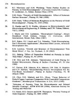
Roll bearings of a
four-high cold rolling stand for aluminium
Operating data
Back-up rolls: roll diameter 1,525 mm
roll body length 2,500 mm
Work rolls:
roll diameter 600 mm
roll body length 2,500 mm
The increased radial clearance C4 is required as the inner rings are fitted tightly and heat up more in operation than the outer rings.
Machining tolerances:
Roll neck +0.350 / +0.440 mm, chock to H7.
Maximum rolling load 26,000 kN
Maximum rolling speed 1,260 m/min
Selection of the back-up roll bearings (fig. 104a)
Radial bearings
The high radial loads are best accommodated, in a limited mounting space and at high speeds, by cylindrical
roller bearings. One four-row cylindrical roller bearing
FAG 527048 (dimensions 900 x 1,220 x 840 mm) is
mounted at each roll end. The bearings feature pintype cages and reach a dynamic load rating of C =
31,500 kN.
Thrust bearings
Since thrust loads in strip rolling stands are low, thrust
bearings are used that are small compared to the radial
bearings. The back-up roll is supported at both ends by
a double-row tapered roller bearing FAG 531295A (dimensions 400 x 650 x 240 mm) with a dynamic load
rating C of 3,450 kN.
Machining tolerances: Shaft to f6.
The cups are not supported radially; axially, they are
adjusted by means of helical springs.
104a: Back-up roll mounting of a four-high cold rolling stand for aluminium (identical bearing arrangements at drive end and operating end)
Selection of the work roll bearings (figs. 104b, c)
Radial bearings
Each roll end is supported on two double-row cylindrical roller bearings FAG 532381.K22 (dimensions
350 x 500 x 190 mm). The bearings feature reduced
tolerances so that all roller rows are evenly loaded,
machined brass cages and an increased radial clearance
C3.
Machining tolerances
Roll neck to p6; chock bore to H6.
Thrust bearings
Locating bearing end (operating end): two angular contact ball bearings FAG 7064MP.UA in X arrangement.
Any two bearings of universal design UA can be
matched in X or O arrangement, yielding a bearing pair
104b: Work roll bearings, operating end
104c: Work roll bearings, drive end
with a narrow axial clearance. The angular contact ball
bearings accommodate the thrust loads from the rolls.
Floating bearing end (drive end): a deep groove ball
bearing FAG 61972M.C3 merely provides axial guidance for the chock.
Machining tolerances: Sleeve to k6; outer rings not radially supported.
Lubrication
All bearings supporting the back-up rolls and work
rolls are oil-mist lubricated. A high-viscosity oil with EP
additives is used as the cylindrical roller bearings – especially at the back-up rolls – are heavily loaded and
have to accommodate operating temperatures of up to
70 ˚C.
105
Work rolls for the finishing section of a
four-high hot wide strip mill
Work roll bearings are often exposed to large amounts
of water or roll coolant. In addition, considerable
amounts of dirt have to be accommodated in hot rolling mills. Therefore, the bearings must be efficiently
sealed. As a rule, they are lubricated with grease, which
improves sealing efficiency. Operators of modern rolling mills endeavour to reduce grease consumption and
damage to the environment caused by escaping greasewater emulsion.
The service life of work roll bearings is mainly dictated
by the loads, rolling speed, lubrication and cleanliness.
Open bearings, as a rule, do not reach their nominal
rating life due to adverse lubricating and cleanliness
conditions. On the other hand, the modified life calculation for sealed bearings usually yields a23 factors > 1,
i. e. the attainable life exceeds the nominal rating life.
In spite of the lower load rating, the value is generally
higher than that reached by an open bearing of the
same size.
Operating data
Lubrication, sealing
Roll body diameter 736 mm; roll body length
2,235 mm; rolling speed 3.5...15 m/s.
Bearing selection, dimensioning
Four-row tapered roller bearings have proved to be a
good choice for work rolls. They accommodate not
only high radial loads but also thrust loads, and they
require only little mounting space. The bearings have a
sliding fit on the roll neck, allowing rapid roll changes.
In the example shown, sealed four-row tapered roller
bearings FAG 563681A (dimensions 482.6 x 615.95
x 330.2 mm) are used.
The bearings are filled with relatively small amounts of
high-quality rolling bearing grease. On each side they
feature a double-lip rubbing seal. The inner lip prevents grease escape from the bearing; the outer lip protects the bearing from moisture that might have penetrated into the chock. No relubrication is required during rolling operation and roll change. The amount of
grease provided during assembly usually suffices for the
duration of one chock regrinding cycle, i. e. for
1,000...1,200 hours of operation. The chocks are fitted
with the conventional external seals (collar seals).
These are filled with a moderately priced, environmentally compatible sealing grease.
105: Work roll mounting for the finishing section of a four-high hot wide strip mill
106
Roll mountings of a two-high ingot slab stand
or ingot billet stand
Operating data
Roll diameter 1,168 mm (46"); roll body length
3,100 mm (122"); rolling speed 2.5...5 m/s; yearly
output of 1 million tons. The mill operates as a reversing stand, i.e. the rolled material moves back and
forth, and the sense of rotation of the rolls alternates
from pass to pass.
The bearing rings are loosely fitted on the roll neck
and in the chocks for easy mounting and dismounting.
The cones creep on the roll neck in circumferential direction. To reduce wear and heat generation, the fitting
surfaces are usually supplied with grease through a helical groove in the bearing bore.
Roll bearings
Lubrication
The work rolls in this example are also supported on
multi-row tapered roller bearings. These bearings require relatively little mounting space and accommodate high radial and thrust loads. The rolls are supported at each end on a four-row tapered roller bearing
FAG 514433A (dimensions 730.25 x 1,035.05
x 755.65 mm).
106: Roll mounting of a two-high ingot slab stand or ingot billet stand
The tapered roller bearings are lubricated with grease
which is continually supplied through grooves in the
faces of cone and spacer ring.
Excess grease escapes through the bores in the central
cup and in the spacers.
107 Combined reduction and cogging wheel gear of a billet mill
Operating data
The billet mill is designed for a monthly output of
55,000 tons. The mill comprises a roughing and a finishing section, each with two vertical and two horizontal stands in alternate arrangement. The drive of the
vertical stands is on top; with this arrangement the
foundations are not as deep as for a bottom drive; on
the other hand, the top drive involves a greater overall
height.
Rated horsepower 1,100/2,200 kW;
motor speed 350/750 min–1.
Compared to two angular contact ball bearings, a four
point bearing offers the advantage of smaller width
and, compared to a deep groove ball bearing, the advantage of smaller axial clearance and higher thrust carrying capacity. The use of four point bearings is, however, limited to applications where the thrust load is
not constantly reversing. The bevel gear shafts feature
the smallest possible axial clearance to ensure perfect
meshing of the spiral-toothed gears. This is achieved
by one duplex pair of angular contact ball bearings
each on the pinion shaft and on the bevel shaft. They
also accommodate the thrust load whereas the radial
load is taken up by cylindrical roller bearings.
Machining tolerances
Bearing selection, dimensioning
Radial loads and thrust loads are accommodated separately: the radial loads by cylindrical roller bearings, the
thrust loads by angular contact ball bearings and four
point bearings. Cylindrical roller bearings offer the
best radial load carrying capacity in a limited mounting space, thus keeping the distance between the gear
shafts to a minimum. One decisive factor in the selection of the bearing size is the diameter of the individual gear shafts determined in the strength calculation.
The two largest cylindrical roller bearings of the gear
are situated on the cogging wheel side and have the
following dimensions: 750 x 1,000 x 250 mm. Axial
location of the four gear shafts is provided by one four
point bearing each which are double direction angular
contact ball bearings.
Cylindrical roller bearings: Shaft to p6; housing to
H6/H7.
Four point bearings and angular contact ball bearings:
Shaft to f6; housing to D10.
The outer rings of the four point bearings and angular
contact ball bearings are fitted into the housing with
clearance to relieve them of radial loads; thus, they accommodate only thrust loads.
Lubrication
Circulating oil lubrication. The bearings and gears
share the same lubrication system. The oil is directly
supplied to the bearings via an oil filter which prevents
contamination of the bearings by particles abraded
from the gears.
107: Combined reduction and cogging wheel gear of a billet mill
108 Work rolls of a section mill
The roll stand frames expand under the influence of
high rolling loads, which can have a negative effect on
the quality of the rolled material. This is usually prevented by means of elaborate roll adjustment mechanisms. Another way to compensate for the negative
effect of the material's elasticity is to hydraulically preload the chocks which support the rolls and their bearing mountings against each other via the roll stands
(see schematic drawing).
Roll neck mountings
9 of the 13 in-line stands of a section mill are fitted
with such hydraulically preloaded chocks. Five of the
nine preloaded stands can also operate as universal
stands. For this purpose they are equipped with two
vertically arranged roll sets.
The horizontal rolls in the roughing stands, which are
loaded with 3,150 kN, are supported in four-row cylindrical roller bearings and four-row tapered roller
bearings of 355.6 x 257.2 x 323.8 mm (fig. a). The
bearings have a loose fit on the roll neck (e7), which
simplifies mounting.
The horizontal rolls are supported by multi-row cylindrical roller bearings and tapered roller bearings. The
cylindrical roller bearings at the drive end compensate
for the length variations caused by heat expansion.
Compensation of length variations through the chock
axially floating in the stand at the drive end is not possible with preloaded chocks.
No loose fit can be provided in those stands where section steels are finish-rolled as the required quality can
only be achieved with accurately guided rolls. For this
reason cylindrical roller bearings and tapered roller
bearings with a tapered bore were selected and pressfitted onto the tapered roll neck. The hydraulic method used simplifies mounting and dismounting. Due to
the lower rolling load (2,550 kN), the horizontal rolls
in this case are supported by double-row cylindrical
roller bearings and tapered roller bearings of 220.1
x 336.6 x 244.5 mm (fig. b).
The vertical rolls are each supported by a tapered roller
bearing pair (dimensions 165.1 x 336.6 x 194.2 mm)
in O arrangement (fig. a). The bearings sit directly on
the rolls. As the rolling stock enters, the vertical rolls
and their bearings are accelerated to operating speed
very quickly. The tapered roller bearings are preloaded
to ensure that the rolling elements always maintain contact with the raceways at these speeds. This is achieved
by matching the tolerances of the bearings and bearing
seats in such a way that the bearings after mounting
have the right preload without any fitting work.
1
2
3
4
5
Hydraulic piston
Upper chock
Piston ram
Lower chock
Frame
108a: Bearing mounting of horizontal rolls in the preloaded roughing stands
and bearing mounting of the vertical rolls
108b: Bearing mounting of horizontal rolls for stands in which section steel is finish-rolled
109
Two-high rolls of a dressing stand
for copper and brass bands
On this dressing stand copper and brass bands with
widths between 500 and 1,050 mm are rolled. The
maximum initial thickness is 4 mm, and the minimum
final thickness is 0.2 mm.
"Counterbending" is one special feature of this stand.
The rolling forces cause an elastic deflection of the
rolls. This deflection is hydraulically compensated for
by counterbending forces. The counterbending forces
are applied to the roll necks on both sides and outside
the roll neck mounting via spherical roller bearings.
This counterbending ensures a uniform band thickness over the entire band width.
Operating data
Two-high roll diameter 690/650 mm; roll body length
1,150 mm; maximum rolling speed 230 m/min; maximum rolling force 8,000 kN; maximum counterbending force 1,300 kN per roll neck.
Accommodation of radial loads
One four-row cylindrical roller bearing FAG 547961
(dimensions 445 x 600 x 435 mm) is mounted at each
end. The cylindrical roller bearings are fitted with pintype cages consisting of two side washers to which the
pins passing through the rollers are fastened. Grooves
in the inner ring faces facilitate dismounting.
Machining tolerances:
roll neck +0.160 / +0.200 mm, chock H6.
Accommodation of thrust loads
At the operating end the axial forces are accommodated by two O arranged angular contact ball bearings
FAG 507227.N10BA (dimensions 400 x 600
x 90 mm).
At the drive end the chock is located on the roll neck
by a deep groove ball bearing FAG 6080M.C3.
Machining tolerances: roll neck to f6, outer ring
radially relieved.
Lubrication
Counterbending bearings
The counterbending forces are applied via spherical
roller bearings FAG 24068B.MB.
Machining tolerances: roll neck to e7, housing to H6.
The cylindrical roller bearings, like the other bearings,
are lubricated with a lithium soap base grease with EP
additives. They can easily be lubricated through lubricating holes and lubricating grooves in the outer rings
and spacers.
Drive end
Operating end
Counterbending bearing
109: Two-high rolls of a dressing stand
Roll bearings
110
Straightening rolls of a rail straightener
Rails for railway track systems or for craneways are hot
rolled in rolling mills. After rolling the rails cool down
on cooling beds but not uniformly, resulting in warping. Afterwards they have to be straightened in rail
straighteners between horizontal and vertical rolls.
The straightening plant consists of two machines one
installed behind the other. In the first machine the rails
run through horizontally arranged rolls, in the second
machine through vertically arranged rolls. Thus the
rails are straightened in both planes after having passed
through the two machines.
Horizontal straightening rolls
The maximum rolling force at the horizontal rolls is
4,200 kN. Depending on the type of rolled stock,
thrust loads of up to 2,000 kN have to be accommodated.
Speeds range from two to 60 min–1.
Double-row cylindrical roller bearings have been provided to accommodate the radial forces and because of
their high load carrying capacity. The higher loaded
cylindrical roller bearing, which is situated directly
beside the roll, was especially developed for supporting
the straightening rolls (dimensions 530 x 780 x 285/
475 mm). The less loaded cylindrical roller bearing has
the dimensions 300 x 460 x 180 mm.
The cylindrical roller bearings are fitted with bored
rollers which are evenly spaced by pins and cage side
washers.
As this design allows the distance between the rollers
to be indefinitely small, the largest possible number of
rollers can be fitted and, adapted to the mounting
space, the highest possible load carrying capacity can
be obtained for the bearing.
The thrust loads are accommodated by two spherical
roller thrust bearings FAG 29448E.MB (dimensions
240 x 440 x 122 mm). They are spring-adjusted.
Each machine features nine straightening rolls, four of
which are being driven. The straightening rolls with
diameters of 600...1,200 mm form an overhung arrangement in order to allow easy replacement.
Demands on the bearing assembly
The mounting space for the bearings is dictated by the
distance of the straightening rolls. In this mounting
space bearings are accommodated which have such a
high load carrying capacity as to allow for reasonable
running times.
The bearing assembly for the straightening rolls must
have maximum rigidity since this determines the accuracy of the rolled stock.
The roll position must be adjustable to the position of
the rolled stock. For this reason the bearing assembly
had to be designed such as to allow for a change of the
position of the straightening rolls by ±50 mm in the
axial direction.
When positioning the straightening rolls, the bearings
must be able to compensate for axial displacements by
up to ±50 mm. This is made possible by providing an
extended inner ring for the cylindrical roller bearing
located beside the straightening roll. The inner ring
width is such that the lips of the two seals always slide
safely on the inner ring even with maximum axial displacement.
The second cylindrical roller bearing is seated, together with the two spherical roller thrust bearings, in a
sleeve which is axially displaceable within the hollow
cylinder. The position of the straightening rolls relative
to the rolled stock is adjusted by means of a ball screw.
Vertical straightening rolls
The vertical straightening roll bearing arrangement is
in principle identical to that of the horizontal straightening rolls. Due to the lower straightening loads, however, smaller bearings can be mounted.
Radial bearings: one axially displaceable double-row
cylindrical roller bearing (dimensions 340 x 520
x 200/305 mm) and one single-row cylindrical roller
bearing FAG NU2244M.C3 (dimensions 220 x 400
x 108 mm).
Thrust bearings: two spherical roller thrust bearings
FAG 29432E (dimensions 160 x 320 x 95 mm).
Lubrication, sealing
system. The oil flow rate per straightening roll unit is
about 10 l/min.
In spite of the high loads and the low speeds it would
be possible to lubricate the cylindrical roller bearings
with grease. However, the spherical roller thrust bearings must be oil-lubricated. Therefore, all bearings are
supplied with oil by means of a central lubricating
At the spherical roller thrust bearing end the unit is
closed by a cover. At the shaft opening in the direction
of the straightening roll two laterally reversed, greaselubricated seal rings prevent oil escape and penetration
of contaminants into the bearings.
110: Horizontal straightening rolls
111
Disk plough
In a disk plough the usual stationary blades are replaced by revolving disks fitted to the plough frame.
The working width of the plough is determined by the
number of disks.
Machining tolerances
on the journal:
– j6 for the smaller bearing,
– k6 for the larger bearing;
in the housing: N7.
Bearing selection
During ploughing both radial and axial loads are imposed on the bearings. Bearing loads depend on soil
conditions and cannot, therefore, be exactly determined. For safety reasons roller bearings with the maximum possible load carrying capacity are used. One
tapered roller bearing FAG 30210A (T3DB050 *) and
one FAG 30306A (T2FB030 *) are installed in O
arrangement and adjusted, via the cone of the smaller
bearing, with zero clearance. This cone must, therefore, be able to slide on the journal.
*) Designation to DIN ISO 355
Lubrication, sealing
Grease lubrication (FAG rolling bearing grease Arcanol
L186V). The bearings are adequately protected from
dirt and atmospheric influences by means spring steel
seals and an additional labyrinth seal.
111: Disk plough