tài liệu về động cơ bước
Bạn đang xem bản rút gọn của tài liệu. Xem và tải ngay bản đầy đủ của tài liệu tại đây (919.64 KB, 19 trang )
Chapter 8
Stepper motors
The motors discussed so far have been effectively analogue in nature, with the
motor's speed being a function of the supply voltage; stepper motors, however,
are essentially digital. The rotary motion in stepper motors occurs in a stepwise
manner from one equiUbrium position to the next, and hence a stepper motor's
speed will be a function of the frequency at which the windings are energised. In
industrial applications, stepper motors are not widely used as the main robotic or
machine-tool drive, but they are widely used as an auxiliary drive (for example
within product feed systems, or as a low power end-effector's actuator) or within a
computer peripheral (for example within a printer). One area where stepper motors
have found widespread use is the drives within small educational robots; this is
largely due to their simplicity of control and the low system cost. There are a
number of characteristics that make a stepper motor the first choice as a servo
drive, including:
• Stepper motors are able to operate with a basic accuracy of ±1 step in an
open-loop system. This inherent accuracy removes the requirement for a
positional or speed transducer, and it therefore reduces the cost of the overall
system.
• Stepper motors can produce high output torques at low angular velocities,
including standstill with the hybrid stepper motor.
• A holding torque can be applied to the load solely with direct-current (d.c.)
excitation of the stepper motor's windings.
• The operation of stepper motors and their associated drive circuits is effectively digital, permitting a relatively simple interface to a digital controller
or to a computer.
• The mechanical construction of stepper motors is both simple and robust,
leading to high mechanical reliability.
215
216
8.1. PRINCIPLES OF STEPPER-MOTOR OPERATION
8.1 Principles of stepper-motor operation
The essential feature of a stepper motor is its ability to translate the changes in
stator winding's excitation into precisely defined changes, steps, of the rotor's position. The positioning is achieved by the magnetic alignment between the teeth of
a stepper motor's stator and rotor. There is a wide range of stepper motors on the
market, but they are all variations of two basic designs: variable-reluctance stepper
motors or hybrid stepper motors. Variable-reluctance stepper motors can be also
found as either multistack or single-stack motors. In the variable-reluctance design, the magnetic flux is provided solely by stator excitation, whereas the hybrid
design uses the interaction between the magnetic flux produced by a rotor-mounted
permanent magnet and that resulting from the stator winding's excitation.
8.1.1
Multistack variable-reluctance motors
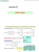
The longitudinal cross section of a multistack variable-reluctance motor is shown in
Figure 8.1(a). The motor is divided into a number of magnetically isolated stacks,
each with its own individual phase winding. The stator of each stack has a number
of poles (four in this example), each with a segment of the phase winding; adjacent
poles are wound in opposite directions. The position of the rotor relative to the
stator is accurately defined whenever a phase winding is excited, where the teeth
of the stator and rotor align to minimise the reluctance of the phase's magnetic
path. To achieve this, the rotor and the stator have identical numbers of teeth.
As can be seen in Figure 8.1, when the teeth of stack A are aligned, the teeth
of stacks B and C are not. Hence by energising phase B after switching off phase
A, a clockwise movement will result; this movement will continue when phase C
is energised. The final step of the sequence is to re-energise phase A. After these
three excitations, stack A will again be aligned, and the motor will have rotated
three steps, or one tooth pitch clockwise, in the process to produce continuous
clockwise rotation. The sequence of excitation will be A:B:C:A:B:C ... ; and for
anticlockwise rotation it will be A:C:A:CB.... The length of each incremental step
is
step length =
360 ^
degrees
N Rx
(8.1)
where A^ is the number of stacks, and RT is the number of rotor teeth per stack.
The motor shown in Figure 8.1 has eight teeth per rotor and three stacks, resulting
in a step length of 15°. A higher-resolution motor, with a smaller step angle, can
be constructed by having more teeth per stack or by having additional stacks. The
use of more stacks will increase the motor length and it will increase the number
of individual phases to be controlled, leading to increased system costs.
The flux generated in each pole will determine the torque which is generated.
In a multistack motor, the four-pole windings can be connected either in series.
CHAPTERS. STEPPER MOTORS
A
^1
B^i
217
C
Winding for stack C
Stator for stack C
Rotor for stack C
(a) Longitudinal cross section through the motor.
(b) Section A-A
(c) Section B-B
(d) Section C-C
Figure 8.1. A three-stack variable reluctance stepper motor; thefluxpath is shown
for phase A.
218
8.1. PRINCIPLES OF STEPPER-MOTOR OPERATION
in series-parallel, or in parallel, resulting in different characteristics for the power
supply and for the controlling semiconductor switch
8.1.2
Single-stack variable-reluctance motors
The essential difference in construction between multistack and single-stack stepper motors is clearly apparent from Figure 8.2, which shows a longitudinal and a
radial cross section of a single-stack motor. The motor consists of only one stack
with three independent stator windings; in addition, the number of teeth on the
rotor and stator are different. The operation of this form of stepper motor is, in
principle, identical to the operation of a multistack stepper motor, with sequential
excitation of the windings resulting in rotation. The direction is again determined
by the order of the excitation sequence, with the sequence A:B:C:A:B:C... for
clockwise rotation, and the sequence A:C:B:A:C:B:A... for anticlockwise rotation.
The length of a step is given by
step length = ——degrees
(8.2)
JLJ'
where RT is the number of rotor teeth which must be a multiple of the number of
motor phases.
Figure 8.2(a) shows the flux paths present when one motor winding is energised. It is readily apparent that a small amount of flux will leak via the teeth
of the unexcited poles, which results in a degree of mutual coupling between the
phases and reduces the performance of the motor in comparison with an equivalent
multistack motor.
8.1.3
Hybrid stepper motors
Figure 8.3 shows a longitudinal cross section of a hybrid stepper motor; the location
of the two stator stacks and the rotor-mounted permanent magnet can also be seen.
The stator poles and the rotor are toothed; tyhe motor illustrated in Figure 8.3 has
sixteen stator teeth and eighteen rotor teeth, and the teeth at either end of the rotor
are displaced by half a tooth pitch relative to each other.
The main flux path is from the rotor magnet's north pole, through the rotor, the
air gap and the stator at section X-X, through the back iron, and finally through
the stator, the air gap and the rotor at section Y-Y, returning to the magnet's south
pole. The motor is wound with two phases, with phase A wound onto poles 1, 3, 5,
and 7, and phase B wound onto poles 2, 4, 6, and 8. In addition, the poles of each
phase are wound in different directions, resulting in the flux directions which are
shown in Table 8.1. For each winding, two different flux directions are possible if
the winding is supplied with a bidirectional current.
The interaction between the stator windings and the rotor magnet can be studied by considering the case when phase A is energised by a positive current. Due to
the presence of the permanent magnet, the flux in the cross section X-X must flow
CHAPTERS. STEPPER MOTORS
219
Winding
Rotor
(a) Axial cross section.
Winding
A 1
Winding
Winding
C
tator
iron
(b) Radial cross section.
Figure 8.2. A single stack variable reluctance stepper motor, the flux path for
phase A is shown in the radial cross section of the motor.
Table 8.1. The relationship between the radial-field direction and the excitation
current for a hybrid stepper motor
Phase
A
A
B
B
Current direction
Positive
Negative
Positive
Negative
Direction of radial field
Outwards
3,7
1,5
4,8
2,6
Inwards
1,5
3,7
2,6
4,8
220
8.1. PRINCIPLES OF STEPPER-MOTOR OPERATION
A-^T
r-^B
Winding
Magnet
otor stack
(a) Longitudinal cross section through the motor.
Phase A
Phase B
(b) A-B cross section
Phase A
Phase B
(c) B-B cross section
Figure 8.3. A hybrid stepper motor. The radial cross-section through the stator
stack shows the flux path if phase A is energised with a positive current. It should
be noted that the view is from the outside of the motor in each case.
CHAPTERS.
STEPPER MOTORS
221
radially outwards, resulting in a flux concentration at poles 3 and 7; the opposite
situation occurs at the other end of the motor, where the flux flows radially in, and
the flux is concentrated in poles 1 and 5. If the magnetic flux is concentrated in
certain poles, the rotor will tend to align along these poles to minimise the reluctance of the air-gap. When phase A is energised with a positive current, this will
occur under poles 3 and 8 of section X-X, and under poles 1 and 5 of section Y-Y.
Continuous rotation of the motor results from the sequential excitation of the two
motor phases if the excitation of winding A has just been removed, and if winding
B is now excited with a positive current, then alignment of the stator and rotor teeth
has to occur under poles 4 and 8 of section X-X and under poles 2 and 6 of section
Y-Y; the rotor has to move clockwise to achieve this alignment. Hence a clockwise
rotation will require the excitation sequence, A+, B+, A-, B-, A+, B+ ..., and an
anticlockwise rotation requires A-f, B-, A-, B+, A+, B - . . . . The drive circuit for
a hybrid stepper motor requires bidirection-current capability, either by the use of
an H-bridge or of two unipolar drives if the motor is wound with bifilar windings.
As with variable-reluctance stepper motors, the step length can be related to
the number of rotor teeth, and, as the complete cycle for a hybrid stepper requires
four states, the step length is given by
90
Step length = —-
(8.3)
RT
where RT is the number of. teeth on the rotor. In the example shown in Figure
7.5, the step angle is 5°; in practice motors are normally available with a somewhat
smaller step length.
8,1.4
Linear stepper motor
The rotary stepper motor, when integrated into a package with a ball screw, is
capable of giving incremental linear motor, and is a widely used solution for many
low cost applications. However, over recent years the true linear stepper motor
has become available. The operation of a linear stepper is in principle no different
to a rotary machine. The key components of a linear stepper motor are shown
Figure 8.4.
The moving assembly has a number of teeth that are similar to those found
on the rotor in a traditional stepper motor, and incorporates two sets of windings
and one permanent magnet. From the diagram it can be seen that one set of teeth
is aligned with the teeth. As in a rotary stepper motor, energisation of a winding
causes the teeth to align. The magnetic flux from the electromagnets also tends
to reinforce the flux lines of one of the permanent magnets and cancels the flux
lines of the other permanent magnet. The attraction of the forces at the time when
peak current is flowing is up to ten times the holding force. When current flow to
the coil is stopped, the moving assembly will align itself to the appropriate tooth
set, and a holding force ensures that their is no movement. The linear stepper
motor controller sets the energisation pattern for the windings so that the motor
8.1. PRINCIPLES OF STEPPER-MOTOR OPERATION
222
Moving
assembly
Winding
Permanent
magnet
[pjt^
Winding
ri_B^^
inn
Track
Figure 8.4. Cross section of a linear stepper motor. The motor consists of a stationary track, and a moving assembly incorporating magnets and the windings. As
shown in the diagram, only one set of teeth on the moving assembly aligns with
the track teeth.
moves smoothly in either direction. By reversing the pattern, the direction the
motor travels is reversed.
8.1.5
Comparison of motor types
The previous sections have briefly reviewed a number of stepper motor configurations. Within a motor-selection procedure the various characteristics of each motor
type will have to be considered, particularly those relating to the step size, the
detent torque, and the rotor inertia:
• Hybrid stepper motors are available with smaller step sizes than variable
reluctance motors; hence they are more suitable for limited-movement, high
resolution applications. The larger step size of variable-reluctance motors, is
more suited to extended high-speed motion, in which the required excitation
the drives will be less than for in hybrid motors.
• The permanent magnets of the hybrid motor will produce a continuous detent
torque, ensuring that the motor retains its position without the necessity of
energising the drive. This is particularly useful for fail-safe applications, for
example, following a power failure.
• The rotor's mass in variable reluctance stepper motors is less than its mass
in hybrid motors; this ensures that the speed of response to a change in the
demand is maximised. As will be discussed later, the inertia determines the
mechanical resonance of the drive system the lower is the inertia, the higher
is the allowable frequency of operation.
CHAPTERS.
STEPPER MOTORS
223
• While a linear motion can be obtained by the combination of a ball screw
with any type of stepper motor, giving a low cost linear actuator, the liners
stepper motor has a number of performance advantages. However, it should
be noted that as with any linear motor, vertical operation can prove problematic.
8.2 Static-position accuracy
The majority of stepper-motor applications require accurate positioning of a mechanical load, for example within a small industrial robot. An externally applied
load torque will give rise to positional errors when the motor is stationary, since
the motor must develop sufficient torque to balance the load torque, otherwise it
will be displaced from its equilibrium position. This error is noncumulative, and
it is independent of the number of steps which have been previously executed. As
the system's allowable error will determine which motor is selected for a particular application, the relationship between the motor, the drive and the load must be
understood.
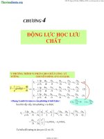
Figure 8.5 shows the relationship between the generated torque and the rotor
position when a single phase is excited. At the point where the rotor and the stator
teeth of the excited phase are in total alignment, no torque will be produced. As
the rotor is moved away, a restoring torque results. The static-torque-rotor position
characteristics repeats with a wavelength of one-rotor-tooth pitch; thus, if the rotor
is moved by greater than ±1/4 tooth pitch, the rotor will not return to the initial
position, but it will move to the next stable position. The shape of the curve is a
function of the mechanical and the magnetic design of the motor, but it can be approximated to a sinusoidal curve with the peak value determined by the excitation
current. If an external load is applied to the motor, the rotor must adopt an equilibrium position where the generated torque is equal to the external load torque. If
the load exceeds the peak torque, the position cannot be held. The positional error
introduced by an external load can be approximated by
0^ = ---'(-^^/^^^^
(8.4)
and this value can be reduced by either increasing the peak torque, Tpk, by an
increased winding current, or by selecting a different motor with a larger number
of rotor teeth.
Another measure of the motor's static-position error is to use the concept of
stiffness, which is given by the gradient of the static-torque-position characteristic
at the equilibrium position, K. The stiffness is given by the gradient of the torqueposition characteristic at the equilibrium point; so, for a given displacement, the
load torque that the motor will be able to support is given by
T = -KOe
(8.5)
224
8.2. STATIC-POSITION
ACCURACY
Gradient = K
Static position error, 6^
-Peak torque
Step position
—Applied Load, T^^
Rotor position
-Half tooth pitch
Figure 8.5. Static-torque rotor-position characteristics showing the static position
error, 9e due to the appHed load TL and the motor stiffness, K.
In some motors the torque-position characteristic is shaped to result in a different stiffness for different displacements; in this case, the stiffness which is closest
to the expected amplitude must be selected.
Example 8.1
Determine the static position error for a stepper motor with eight rotor teeth, rated
at 1.2 Nm, when a load of 0.6 Nm is applied.
The approximate positional error is defined by equation 8.4, hence
sm-\-TL/Tpk)
RT
^
sin-'{-0.6/1.2)
8
3.8°
In practice this value is less than that experienced by the actual system, due to the
approximations used.
CHAPTERS. STEPPER MOTORS
225
8.3 Torque-speed characteristics
In the application of a stepper motor to a motion-control system, the designer needs
knowledge of the motor's torque speed characteristics. This information is supplied
by the manufacturers in the form of pull-out characteristics, which show the maximum torque that can be developed at any speed (see Figure 8.6). If the applied
load torque exceeds the torque that can be generated by the motor, the motor will
pull out of synchronism with the magnetic field, and it will stall. From Figure 8.6,
the following points can be noted:
• The motor is capable of operating with a load of T', up to a speed of A^'
(steps s~^). Above this speed, the motor will not start.
• There are significant dips in the pull-out-torque curve at a number of speeds.
These dips are caused by resonance between the motor and the excitation
frequency.
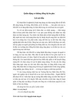
• At low motor speeds the phase currents are effectively rectangular. At high
speeds, the time constant for the phase current's rise and decay will become a
significant proportion of the total available excitation time (see Figure 8.7).
Therefore, the effective phase current, and hence the torque which is produced, will be reduced. In addition, as shown in Figure 8.7, high speeds
result in an induced stator voltage which also distorts the current waveform.
This is particularly marked with hybrid stepper motors because of the presence of the permanent magnet in the rotor.
As shown in Figure 8.7, the phase currents of a stepper motor are almost rectangular at low speeds, allowing the pull-out torque of a motor to be determined from
the static-torque-rotor-position characteristics for a particular excitation scheme.
The pull-out torque can, within certain limits, be dependent on the driven inertia.
With a high load inertia, the pulsating variations of the motor torque will only lead
to small variations of the motor speed. Under these conditions, the pull-out torque
can be considered to be equal to the average motor torque. If the sum of the motor
and the load inertias is low, the motor will stall whenever the load torque exceeds
the generated torque.
Since stepper motors are designed to operate in discrete steps, at very slow
speeds, the motor will come to rest between each excitation. Due to the dynamics
of stepper motors and their loads, the single-step transient behaviour tends to be
very oscillatory, and the effects of this have to be considered in the design of an
overall system, because they can result in significant accuracy problems in a poorly
damped system. As discussed in Section 3.6, the undamped natural frequency of
oscillation in a drive system was shown to be
(8.6)
226
8.4. CONTROL OF STEPPER MOTORS
Torque
Steps per second
Figure 8.6. Typical pull-out torque-speed characteristics of a stepper motor: the
dips in the curve are resonance points. In order to achieve torque throughout the
speed range, a value less than the peak torque must be selected.
where K is the stiffness at the rotor position under consideration and Jtot is the
sum of the motor inertia and the load inertia reflected back to the motor.
This oscillating behaviour can be damped out, if required, for single-step operations by the use of mechanical (that is, viscous) or electrical damping. Excessive
vibration of the mechanical system will result in wear, leading to premature mechanical failures.
This resonance behaviour results in a loss of torque at well-defined stepping
rates, as shown in the pull-out torque-speed characteristic in Figure 8.6. These
stepping rates can be determined from the natural frequency of the system, and
they are given by.
(for*=l,2,...)
(8.7)
Hence, if the motor and load have a natural resonance frequency of 120 Hz, the
dips in the speed-torque curve will occur at 40, 60, 120, steps s~^
8.4 Control of stepper motors
The design of a drive system that incorporates a stepper motor should start with
consideration of the steady-state performance; the choice of the type and step angle of the stepper motor is dictated largely by the maximum allowable positional
error and by the maximum stepping rate which is required. While a stepper motor
can be operated under either an open-loop or a closed-loop control system, this
chapter will primarily discuss the open-loop approach. Closed-loop stepper-motor
CHAPTERS. STEPPER MOTORS
227
Winding voltage
and current
Winding voltage
and current
Time
Time
(a)
(b)
Winding voltage
and current
Time
(c)
Figure 8.7. Current through a unipolar stepper-motor winding as a function of
speed. The appHed voltage is shown by the dotted line: (a) low speed, (b) medium
speed and (c) high speed.
drives are no different from any other closed-loop drive, which will be discussed
in Chapter 10. Due to the inherent operation of a stepper motor, one change of
phase excitation will result in the motor moving a specified, and accurately known,
distance. The stepper motor's position is controlled by generating a pulse train of
known length, which is converted into the correct sequence of winding excitations
by a translator, the winding power being switched by the drive circuit. A block
diagram of a typical open-loop-stepper drive system is shown in Figure 8.8.
During the design process, information is required on the restrictions that have
to be placed on the timing of the pulse train to ensure satisfactory operation. These
restrictions can be sunmiarised as:
• The maximum step rate permitted for the required load torque. This can be
determined from the motor's pull-out characteristic.
• The motor's transient performance. If the load has a high inertia, the motor's
speed must be ramped up to ensure that the motor remains in synchronism
with the step demand.
There is no feedback from the motor or load to the controller in an open-loop
system, so it is imperative that the motor responds correctly to each incoming pulse
because any loss in position cannot be detected and then compensated for. In order
to achieve a satisfactory performance from a stepper motor, the operation of the
pulse generator should be carefully considered during the design process.
228
8.4. CONTROL OF STEPPER MOTORS
Direction
T
Clock
Clock
Pulse generator
Translator
Power Stage
Direction
Stop/start
Half or full
step
Figure 8.8. A block diagram of an open-loop stepper drive.
8.4.1
Open-loop control
An open-loop position-controller for a stepper-motor generates a string of pulses,
at a fixed frequency, until the motor reaches the target position. If the pulse rate is
set too high, and the load has a high inertia or static friction, the motor may not be
able to accelerate to the required speed without losing steps; or, in an extreme case,
it can fail to rotate at all. If the pulse frequency to the motor is ramped up, it will be
possible to ensure that, under normal operating conditions, the motor does not lose
synchronism. The maximum allowable starting rate for a motor can be determined
from a knowledge of the motor and the load. The equation of motion for a system
of inertia Jtot is given by
Tm — TL — Jtot
(8.8)
where Ti is the load torque and Tm is the average output torque of the motor. If
this equation solved using the initial conditions t = 0,6 =^ 6e (where 6 is the static
error due to the load torque), and d9/dt = 0 then
e=
Jtot
+ 0e
(8.9)
After one excitation period of length tp, the rotor will be at a new position 9f (see
Figure 8.9); the maximum allowable initial stepping rate can determined to be;
J start — 7~ —
Jtot{6f — Oe)
(8.10)
As expected, the lower the load inertia, or the greater the motor torque, the higher
the permissible starting frequency. The starting frequency in most applications
will be lower than the at-speed frequency. Therefore, an acceleration-deceleration
CHAPTERS.
STEPPER MOTORS
229
Figure 8.9. The static-torque characteristic for a stepper motor with an appUed
load. When a phase is energised the motor has to move from 9e to Of without loss
of synchronism. The three curves are the individual static-torque characteristics of
the individual phases.
capabiUty must be provided; this is normally in the form of a variable-frequency
pulse generator. To realise this characteristics, a number of different approaches
can be taken, based either on dedicated hardware or on microprocessors.
8.4.2
Translators and drive circuits
The output from the pulse generator forms the input to the stepper-motor's translator and drive circuit. The drive circuit for a stepper motor is normally of a lower
rating and complexity than for the motors that have been discussed previously.
The function of the translator is to control the excitation of the motor phases in response to the incoming pulses and the required direction of motion; this is achieved
through the use of a shift register and a look-up table, which is normally provided
within a single integrated circuit. The output sequence for a full step switching
pattern is given in Table 8.2.
Since the phase windings of both hybrid and variable-reluctance stepper motors
are electrically isolated and controlled by individual drive circuits, the possibility
of energising a number of phases simultaneously can be considered. If one winding
of a stepper motor is excited, a stable-equilibrium point will occur every rotor-pole
pitch at positions A', B' and C in the case of a three-stack variable-reluctance
motor, Figure 8.10.
If, on the other hand, two phase-windings are excited, the resultant torque summation will produce two new equilibrium points, BA' and CB^ which are midway
between the single-winding equilibrium points. Therefore, if the windings of the
variable reluctance stepper motor considered earlier in this chapter are excited in
230
8.4. CONTROL OF STEPPER MOTORS
Table 8.2. The full step sequence: the four power-stage outputs are identified in
Figure 8.8
"step
A
B
C
D
1
On Off Off Off
2
Off On Off Off
• 3
Off Off On Off
4
Off Off Off On
5
On Off Off Off
Table 8.3. Half step sequence
Step
1
2
3
4
5
6
7
8
A
On
On
On
Off
Off
Off
Off
On
B
Off
On
On
On
Off
Off
Off
Off
C
Off
Off
Off
On
On
On
Off
Off
D
Off
Off
Off
Off
Off
On
On
On
the sequence A, BA, B, CB, C, AC, A . . ., each excitation change will result in a
movement of half its normal step. This approach to stepper-motor control is termed
half-stepping. It should also be noted that the peak-torque resultant for multiphase
energisation is greater than that which occurs when a single phase is used. This
is of particular importance when the number of stacks is greater than three. It is
normal practice to energise three or four phases in any one time in the control of a
seven-stack stepper motor. Half-stepping operations can be applied to hybrid stepper motors, but due to the bipolar nature of these motors' drives the power capacity
of the drive system has to be increased. For a forty per cent increase in the torque,
the power supply has to be increased by one hundred per cent.
In half-stepping, the phases are energised at the rated current. If the current
in each phase is controlled, it is possible to produce further equilibrium points,
leading to further subdivisions of a motor's basic step; this approach is termed
mini-stepping. While this approach will result in a greater resolution, each phase's
current must be individually controlled, leading to additional complexity in the
drive system; the switching pattern is given in Table 8.3.
Hybrid stepper motosr have a bipolar-current requirement, whereas variable
reluctance stepper motors require a unipolar drive. In a unipolar drive, the output
of the translator is directly used to switch the individual phase currents; the power
devices are normally MOSFETs. Since the winding current's decay time has an
adverse effect stepper-motor performance, it is common practice to add a zener
CHAPTERS. STEPPER MOTORS
231
|Torque
A
(a)
TTorque
BA
/
CB
-S
t
.•••
/•
N
\ V/
A
I
:' \
/
/
/
/
\;
1
I
/
N
t
\
/
/
^
.•••
.•••
^
^
\
\
\
Position
\
\ I
\ I
-18°-
(b)
Figure 8.10. Static-rotor rotor-position characteristics when: (a) one phase is excited and (b) two phases are excited. If both curves are combined the step angle is
reduced from 18° to 9°.
232
8.4. CONTROL OF STEPPER MOTORS
..
\/
^s
1
\
Vdiode + V , _ ,
;
/ \
'--^
With zener diode
(a) Circui t diagram.
(b) Comparison of the current decay with and
without the zener diode.
Figure 8.11. The use of a zener diode to modify the delay characteristics of the
winding current, the currents are shown as a dotted Hne.
(a)
(b)
Figure 8.12. The use of two unipolar drives to control one phase of a bifilar-wound
motor: (a) the circuit diagram and (b) the bifilar windings.
diode or a resistor to the flywheel path which ensures that the current decays at
an increased rate , (see Figure 8.11). Bidirectional winding currents can be controlled by using an H-bridge, identical to that used in d.c. brushed motors. With
this configuration, the free-wheeling current decays more rapidly, because of the
opposition of the supply voltage, so it is not necessary to add a resistance or zener
diodes to the flywheel path. A different approach is the use of a motor wound with
a bifilar winding; this will result in a reduction in the number of switching devices
used to control a phase from four to two (see Figure 8.12). Each of the bifilar
windings has as many turns as the equivalent winding for a bipolar motor, so the
size and cost of the motor increases; but this is counterbalanced by an equivalent
reduction in the drive costs. As the two windings share the same pole, there is
close magnetic coupling between the coils; this must be taken into account when
designing a drive system.
CHAPTERS. STEPPER MOTORS
8.5
233
Summary
This chapter has briefly reviewed the theory and control of a range of stepper motors, and it has been shown that stepper motors are able to provide a low-cost
solution to motion-control problems, provided that the limitations of the motors
are fully appreciated during the design process.