AN0539 frequency and resolution options for PWM outputs
Bạn đang xem bản rút gọn của tài liệu. Xem và tải ngay bản đầy đủ của tài liệu tại đây (149.04 KB, 13 trang )
AN539
Frequency and Resolution Options for PWM Outputs
(PR1 = 18h), then PWM frequency is:
Authors:
Stan D’Souza and Sumit Mitra
Microchip Technology Inc.
Note however that the duty cycle resolution is a little
less than 7-bits.
INTRODUCTION
The PIC17C42 is equipped with two high frequency
Pulse Width Modulation (PWM) outputs. In a pulse
width modulated signal the period of the signal is
(usually) kept fixed, while the duty cycle is varied. In this
application note, we will discuss options in selecting
PWM frequency and resolution.
This application note assumes that the internal clock is
used for the time-base, which is typically the preferred
setup. Also, throughout this application note, PWM1
output is used in examples, Timer1 is assumed to be
the time-base.
Definition of terms:
Period of a PWM output is the duration after which the
PWM pattern will repeat itself.
Frequency of a PWM output is = 1/Period.
Resolution of a PWM output is the granularity with
which the duty cycle can be modulated.
In the case of the PIC17C42, when using PWM1 with
Timer1 as the time-base:
PWM1 period = [(PR1) + 1] x 4TOSC
PWM1 duty cycle =
where
(DC1) x TOSC
PR1
= period register for Timer1
DC1
= PW1DCH, PW2DCL
concantenated (10-bit value)
TOSC = oscillator period
At 16 MHz oscillator frequency, TOSC = 62.5 ns. The
user can control the frequency of the PWM output by
altering the 'period' value of the time-base. For
example, if the period is chosen to be 100 TOSC
FIGURE 1:
1/(100 x 62.5) ns = 160 kHz.
Useful and Common PWM Modes
While a variety of period values can be selected, the following modes would be most commonly used:
10-bit Mode: In this mode PWM duty cycle has full
10-bit resolution (maximum offered by the PIC17C42).
The period register PR1 is set at FFh. PWM period =
1024TOSC = 64 µs. PWM frequency is 15.625 kHz. The
user must write both PW1DCH and PW1DCL to update
PWM output. See Appendix A for an example of code
that modulates 10-bit resolution PWM output
(PWM10.LST).
8-bit Hi-Resolution Mode: In this mode, the user has
only an 8-bit quantity to write to the duty-cycle register.
Period register is set at 3Fh (63 decimal), such that
PWM period is 256Tosc. To write the 8-bit duty-cycle
value, first the 8th bit is right shifted two bits. The upper
six bits are written to PW1DCH and the lower two bits
are written to PW1DCL as follows:
;8-bit
CLRF
RRCF
RRCF
RRCF
RRCF
ANDLW
MOVPF
MOVFP
duty-cycle value is in WREG
TEMP
;
WREG
;
TEMP
;
WREG
;
TEMP
;Shift right twice
b'00111111 ;Mask off two-high bits
WREG,PW1DCH ;Write duty-cycle values
TEMP,PW1DCL ;
Note that in 8-bit, hi-resolution mode, maximum PWM
frequency is attained. For example, at 16 MHz clock,
PWM period = 256TOSC = 16 µs; PWM frequency =
62.5 kHz. See appendix B for an example code that
generates 8-bit low high resolution PWM output
(PWM8HI.LST).
PWM OUTPUT
PWM
Duty-Cycle
Period
PWM frequency = 1/period
1997 Microchip Technology Inc.
DS00539C-page 1
AN539
FIGURE 2:
VARIOUS PWM MODES
DC9
DC2
DC1 DC0
10-bit
PW1DCH
PW1DCL
DC2
DC9
DC1 DC0
0
PW1DCH
PW1DCL
DC7
0
8-bit low
resolution
0
DC2
DC1 DC0
8-bit high
resolution
0
PW1DCH
PW1DCL
Note: DC registers suited for 16-bit computation, using 10 MSb only.
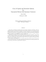
generate an analog signal, higher frequency may be
desirable. In any case, the lowest frequency achievable
(using internal clock for the timer) is (FOSC/1024). At
16 MHz oscillator input, the lowest PWM frequency
possible is 15.625 kHz. At resolutions less than 10-bit,
higher frequencies are possible (Figure 3). For example, if 7-bit resolution is chosen, then the PWM frequencies can be 15.625 kHz, 31.25 kHz, 62.5 kHz or
125 kHz. The reader will note that it’s how the 7-bits are
placed within the 10-bit possible duty cycle value.
8-bit Low Resolution Mode
In this mode, the user still has only an 8-bit quantity to
write to the duty cycle register. However, the desired
frequency of the PWM output is less, due to the nature
of the application. For example, if the PWM output is
being used to drive a motor through a power stage, the
power transistors, (or devices) due to their switching
time, will prefer PWM frequency not to exceed a certain
frequency. In the previous section, we derived an 8-bit
resolution PWM output at 62.5 kHz.
Conversely, if a certain frequency is desired, such as
44 kHz, then referring to Figure 1, resolution can be
8.5-bit or 7.5-bit or 6.5-bit etc.
To attain a low-resolution PWM output, PW1DCL is
always kept at zero. The 8-bit value is written to
PW1DCH. The period (PR1) is set at FFh (i.e., 256 TCY
equals 1024TOSC [15.625 kHz]). See Appendix C for an
example code that produces 8-bit low resolution PWM
output (PWM8LO.LST).
Summary
The frequency and resolution of the PWM outputs of
the PIC17C42 can be traded off against each other to
best suit the application. The oscillator frequency can
also be varied to adjust PWM frequency, if necessary.
External clock should be used as timer time-base to
generate very low frequency PWM output.
Choosing Resolution and Frequency of PWM
Output
Actually, the resolution and the frequency of the PWM
output is selectable within certain limits. The user will
need to first define the requirements based on the
application. There may be an upper limit to the
frequency if the PWM is being used to drive motors.
On the other hand, if the PWM is being filtered to
PWM FREQUENCY vs. RESOLUTION
PWM frequency vs. resolution
for FOSC = 16 MHz
Timer time-base = internal clock
250
Log scale
At a given oscillator frequency
(16 MHz in this figure), a family
of curves represents the PWM freq/resolution
combinations possible.
PWM frequency (kHz)
FIGURE 3:
125
62.5
(44 kHz, 8.5 bits)
31.25
15.625
6
7
8
9
10
PWM resolution
DS00539C-page 2
1997 Microchip Technology Inc.
AN539
Please check the Microchip BBS for the latest version of the source code. Microchip’s Worldwide Web Address:
www.microchip.com; Bulletin Board Support: MCHIPBBS using CompuServe® (CompuServe membership not
required).
APPENDIX A: PWM10.LST
MPASM 01.40 Released
LOC OBJECT CODE
VALUE
00000021
00000020
00000022
00000001
0000
0000 C063
0010
0010
0010 C054
0020
0020
0020 C046
0030
00001
00002
00003
00004
00005
00001
00002
00264
00006
00007
00008
00009
00010
00011
00012
00013
00014
00015
00016
00028
00029
00030
00031
00032
00033
00034
00035
00036
00037
00038
00039
00040
00041
00042
00043
00044
00045
00046
00047
00048
00049
00050
00051
00052
00053
00054
00055
00056
00057
00058
00059
00060
00061
00062
PWM8HI.ASM
1-16-1997
13:59:20
PAGE
1
LINE SOURCE TEXT
TITLE
“PULSE WIDTH MODULATION 8 BIT HIGH RESOLUTION”
PROCESSOR
PIC17C42
#include
“p17c42.inc”
LIST
; P17C42.INC Standard Header File, Version 1.03 Microchip Technology, Inc.
LIST
PWM_HI equ
0x21
PWM_LO equ
0x20
TEMP
equ
0x22
;
F
equ
1
;
;The user would generate a 16 bit value which is saved in ram
;locations PWM_HI and PWM_LO byte. In 8 bit hi-res mode, the program
;transfers the 8 bit values to the lo Duty Cycle (DC) registers, to
;generate the required 8 bit hi-res PWM.
LIST
;
;
;This is a short program to demonstrate how to generate PWM outputs with
;8 bit resolution. Since a 10Mhz crystal was used in the test system.
;The max. period = 256x100nS = 25.6uS or 39KHz. This program
;keeps the period constant and varies the duty cycle (which corresponds
;to the most significant 10 bits of the 16 bit value PWM_LO&PWM_HI).
;This program is interrupt driven, i.e. the update to the Duty cycle
;is done in the TMR0 interrupt, which then enables the pwm interrupt.
;The period update is done during the pwm interrupt. The pwm output
;ramps up from 0% to 100% duty cycle and then repeats. The full
;sweep takes approx. 13.3 secs.
;
;
;
;
Program:
PWM8HI.ASM
;
Revision Date:
;
12-12-95
Compatibility with MPASMWIN 1.30
;
;*********************************************************************
;
ORG
0
goto
start
;
ORG
0x10
;vector for TMR0 interrupt
TMR0_int
goto
service_TMR0
;service TMR0
;
ORG
0x0020
;vector for pwm interrupt
pwm_int
goto
service_pwm
;service pwm only
;
ORG
0x0030
;
1997 Microchip Technology Inc.
DS00539C-page 3
AN539
0030
0030 B802
Message[302]:
0031 2910
0032 B062
Message[302]:
0033 0114
0034 B803
0035 2922
0036 6A21
0037 190A
0038 1922
0039 190A
003A 1922
003B B53F
Message[302]:
003C 4012
Warning[202]:
003D 7022
Message[302]:
003E 2916
003F B011
Message[302]:
0040 4017
0041 B801
Message[302]:
0042 2917
Message[302]:
0043 2916
0044 8307
0045 0005
0046
0046 B802
0047 B062
Message[302]:
0048 0114
0049 B801
Message[302]:
004A 8C17
004B 0005
004C
004C
004D
004E
004F
0050
0051
0052
0053
B020
650A
290B
290C
B031
0121
8107
0002
DS00539C-page 4
00063 ;initialize internal hardware to generate the pwm output
00064 init_pwm8hi
00065
movlb
2
Register in operand not in bank 0. Ensure that bank bits are correct.
00066
clrf
TMR1, F
;clear timer 1
00067
;used to “drive” pwm1
00068
movlw
62
;set period=39khz
Register in operand not in bank 0. Ensure that bank bits are correct.
00069
movwf
PR1
;
/
00070
movlb
3
00071
clrf
TEMP, F
;TEMP = mask for pw1dcl
00072
movfp
PWM_HI,WREG
;get duty cyl. hi byte
00073
rrcf
WREG, F
;rotate hi through carry
00074
rrcf
TEMP, F
;rotate into lo byte
00075
rrcf
WREG, F
;repeat for 2nd lsb
00076
rrcf
TEMP, F
;
/
00077
andlw
B’00111111’
;mask hi bits
Register in operand not in bank 0. Ensure that bank bits are correct.
00078
movpf
W,PW1DCH
;save in high
Argument out of range. Least significant bits used.
00079
movfp
TEMP,PW1DCL
;save in low
Register in operand not in bank 0. Ensure that bank bits are correct.
00080
clrf
TCON1, F
;tmr1 inc. internally
00081
;as 8 bit counter
00082
movlw
B’00010001’
;start tmr1 and
Register in operand not in bank 0. Ensure that bank bits are correct.
00083
movpf
W,TCON2
;enable pwm1
00084
movlb
1
Register in operand not in bank 0. Ensure that bank bits are correct.
00085
clrf
PIE, F
;clr all int. enables
Register in operand not in bank 0. Ensure that bank bits are correct.
00086
clrf
PIR, F
;clear all interrupts
00087
bsf
INTSTA,PEIE
;except peripheral int.
00088
retfie
00089 ;
00090 ;
00091 ;everytime a new value is written to the PWM_HI, PWM_LO regs, the
00092 ;tmr1 interrupt is enabled. The DC value are written just before
00093 ;the “pwm interrupt” is enabled. Here the new period register is
00094 ;updated. In this example, period is kept constant at 62 Tcyl.
00095 service_pwm
00096
;if the period changed, write new value here.
00097
movlb
2
;select bank 2
00098
movlw
62
;period = 62 Tcyl.
Register in operand not in bank 0. Ensure that bank bits are correct.
00099
movwf
PR1
;
/
00100
movlb
1
;disable tmr1 int
Register in operand not in bank 0. Ensure that bank bits are correct.
00101
bcf
PIE,TMR1IE
;
/
00102
retfie
00103 ;
00104
PAGE
00105 ;This part of the program is basically used to simmulate a change
00106 ;which would be used to drive the pwm output.
00107 ;
00108 ;the TMR0 is set up to interrupt every 52 mS.
00109 init_TMR0
00110
movlw
B’00100000’
;set up TMR0 timer
00111
movfp
WREG,T0STA
;
/
00112
clrf
TMR0L, F
;clear TMR0
00113
clrf
TMR0H, F
;
/
00114
movlw
31
;init pwm at 50%
00115
movwf
PWM_HI
;save in high
00116
bsf
INTSTA,T0IE
;enable TMR0 int.
00117
return
00118 ;
1997 Microchip Technology Inc.
AN539
00119 ;Every TMR0 interrupt, the PWM_HI&PWM_LO bytes are incremented by 1.
00120 ;Only the 8 most significant bits are incremented.
00121 ;
0054
00122 service_TMR0
0054 8D07
00123
bcf
INTSTA,T0IF
;reset int flag
00124
;do a pseudo inc of the 8 bit PWM_HI.
0055 1521
00125
incf
PWM_HI, F
;inc PWM_HI
00126
;now load the values into the Duty Cycle registers
0056 B803
00127
movlb
3
;bank 3
0057 2922
00128
clrf
TEMP, F
;TEMP = mask for pw1dcl
0058 6A21
00129
movfp
PWM_HI,WREG
;get duty cyl. hi byte
0059 190A
00130
rrcf
WREG, F
;rotate hi through carry
005A 1922
00131
rrcf
TEMP, F
;rotate into lo byte
005B 190A
00132
rrcf
WREG, F
;repeat for 2nd lsb
005C 1922
00133
rrcf
TEMP, F
;
/
005D B53F
00134
andlw
B’00111111’
;mask hi bits
Message[302]: Register in operand not in bank 0. Ensure that bank bits are correct.
005E 4A12
00135
movpf
WREG,PW1DCH
;save in high
Warning[202]: Argument out of range. Least significant bits used.
005F 7022
00136
movfp
TEMP,PW1DCL
;save in low
0060 B801
00137
movlb
1
Message[302]: Register in operand not in bank 0. Ensure that bank bits are correct.
0061 8417
00138
bsf
PIE,TMR1IE
;enable tmr1 int
0062 0005
00139
retfie
00140 ;
00141
PAGE
00142 ;
0063
00143 start
0063 8406
00144
bsf
CPUSTA,GLINTD
;disable interrupts
0064 E04C
00145
call
init_TMR0
;initailize the TMR0 tmr
00146
;for test purposes
0065 E030
00147
call
init_pwm8hi
;initialize 8 bit pwm
0066 C066
00148 loop
goto
loop
;spin wheels.
00149 ;
00150
00151
END
MEMORY USAGE MAP (‘X’ = Used, ‘-’ = Unused)
0000 : X--------------- X--------------- X--------------- XXXXXXXXXXXXXXXX
0040 : XXXXXXXXXXXXXXXX XXXXXXXXXXXXXXXX XXXXXXX--------- ---------------All other memory blocks unused.
Program Memory Words Used:
Errors
:
Warnings :
Messages :
0
2 reported,
11 reported,
1997 Microchip Technology Inc.
58
0 suppressed
0 suppressed
DS00539C-page 5
AN539
Please check the Microchip BBS for the latest version of the source code. Microchip’s Worldwide Web Address:
www.microchip.com; Bulletin Board Support: MCHIPBBS using CompuServe® (CompuServe membership not
required).
APPENDIX B: PWM8HI.LST
MPASM 01.40 Released
LOC OBJECT CODE
VALUE
00000021
00000020
00000022
00000001
0000
0000 C063
0010
0010
0010 C054
0020
0020
0020 C046
0030
DS00539C-page 6
00001
00002
00003
00004
00005
00001
00002
00264
00006
00007
00008
00009
00010
00011
00012
00013
00014
00015
00016
00028
00029
00030
00031
00032
00033
00034
00035
00036
00037
00038
00039
00040
00041
00042
00043
00044
00045
00046
00047
00048
00049
00050
00051
00052
00053
00054
00055
00056
00057
00058
00059
00060
00061
00062
PWM8HI.ASM
1-16-1997
13:59:20
PAGE
1
LINE SOURCE TEXT
TITLE
“PULSE WIDTH MODULATION 8 BIT HIGH RESOLUTION”
PROCESSOR
PIC17C42
#include
“p17c42.inc”
LIST
;P17C42.INC Standard Header File, Version 1.03 Microchip Technology, Inc.
LIST
PWM_HI equ
0x21
PWM_LO equ
0x20
TEMP
equ
0x22
;
F
equ
1
;
;The user would generate a 16 bit value which is saved in ram
;locations PWM_HI and PWM_LO byte. In 8 bit hi-res mode, the program
;transfers the 8 bit values to the lo Duty Cycle (DC) registers, to
;generate the required 8 bit hi-res PWM.
LIST
;
;
;This is a short program to demonstrate how to generate PWM outputs with
;8 bit resolution. Since a 10Mhz crystal was used in the test system.
;The max. period = 256x100nS = 25.6uS or 39KHz. This program
;keeps the period constant and varies the duty cycle (which corresponds
;to the most significant 10 bits of the 16 bit value PWM_LO&PWM_HI).
;This program is interrupt driven, i.e. the update to the Duty cycle
;is done in the TMR0 interrupt, which then enables the pwm interrupt.
;The period update is done during the pwm interrupt. The pwm output
;ramps up from 0% to 100% duty cycle and then repeats. The full
;sweep takes approx. 13.3 secs.
;
;
;
;
Program:
PWM8HI.ASM
;
Revision Date:
;
12-12-95
Compatibility with MPASMWIN 1.30
;
;**********************************************************************
;
ORG 0
goto
start
;
ORG
0x10
;vector for TMR0 interrupt
TMR0_int
goto
service_TMR0
;service TMR0
;
ORG
0x0020
;vector for pwm interrupt
pwm_int
goto
service_pwm
;service pwm only
;
ORG
0x0030
;
1997 Microchip Technology Inc.
AN539
0030
0030 B802
Message[302]:
0031 2910
0032 B062
Message[302]:
0033 0114
0034 B803
0035 2922
0036 6A21
0037 190A
0038 1922
0039 190A
003A 1922
003B B53F
Message[302]:
003C 4012
Warning[202]:
003D 7022
Message[302]:
003E 2916
003F B011
Message[302]:
0040 4017
0041 B801
Message[302]:
0042 2917
Message[302]:
0043 2916
0044 8307
0045 0005
0046
0046 B802
0047 B062
Message[302]:
0048 0114
0049 B801
Message[302]:
004A 8C17
004B 0005
004C
004C
004D
004E
004F
0050
0051
0052
0053
B020
650A
290B
290C
B031
0121
8107
0002
00063 ;initialize internal hardware to generate the pwm output
00064 init_pwm8hi
00065
movlb
2
Register in operand not in bank 0. Ensure that bank bits are correct.
00066
clrf
TMR1, F
;clear timer 1
00067
;used to “drive” pwm1
00068
movlw
62
;set period=39khz
Register in operand not in bank 0. Ensure that bank bits are correct.
00069
movwf
PR1
;
/
00070
movlb
3
00071
clrf
TEMP, F
;TEMP = mask for pw1dcl
00072
movfp
PWM_HI,WREG
;get duty cyl. hi byte
00073
rrcf
WREG, F
;rotate hi through carry
00074
rrcf
TEMP, F
;rotate into lo byte
00075
rrcf
WREG, F
;repeat for 2nd lsb
00076
rrcf
TEMP, F
;
/
00077
andlw
B’00111111’
;mask hi bits
Register in operand not in bank 0. Ensure that bank bits are correct.
00078
movpf
W,PW1DCH
;save in high
Argument out of range. Least significant bits used.
00079
movfp
TEMP,PW1DCL
;save in low
Register in operand not in bank 0. Ensure that bank bits are correct.
00080
clrf
TCON1, F
;tmr1 inc. internally
00081
;as 8 bit counter
00082
movlw
B’00010001’
;start tmr1 and
Register in operand not in bank 0. Ensure that bank bits are correct.
00083
movpf
W,TCON2
;enable pwm1
00084
movlb
1
Register in operand not in bank 0. Ensure that bank bits are correct.
00085
clrf
PIE, F
;clr all int. enables
Register in operand not in bank 0. Ensure that bank bits are correct.
00086
clrf
PIR, F
;clear all interrupts
00087
bsf
INTSTA,PEIE
;except peripheral int.
00088
retfie
00089 ;
00090 ;
00091 ;everytime a new value is written to the PWM_HI, PWM_LO regs, the
00092 ;tmr1 interrupts is enabled. The DC value are written just before
00093 ;the “pwm interrupt” is enabled. Here the new period register is
00094 ;updated. In this example, period is kept constant at 62 Tcyl.
00095 service_pwm
00096
;if the period changed, write new value here.
00097
movlb
2
;select bank 2
00098
movlw
62
;period = 62 Tcyl.
Register in operand not in bank 0. Ensure that bank bits are correct.
00099
movwf
PR1
;
/
00100
movlb
1
;disable tmr1 int
Register in operand not in bank 0. Ensure that bank bits are correct.
00101
bcf
PIE,TMR1IE
;
/
00102
retfie
00103 ;
00104
PAGE
00105 ;This part of the program is basically used to simmulate a change
00106 ;which would be used to drive the pwm output.
00107 ;
00108 ;the TMR0 is set up to interrupt every 52 mS.
00109 init_TMR0
00110
movlw
B’00100000’
;set up TMR0 timer
00111
movfp
WREG,T0STA
;
/
00112
clrf
TMR0L, F
;clear TMR0
00113
clrf
TMR0H, F
;
/
00114
movlw
31
;init pwm at 50%
00115
movwf
PWM_HI
;save in high
00116
bsf
INTSTA,T0IE
;enable TMR0 int.
00117
return
00118 ;
1997 Microchip Technology Inc.
DS00539C-page 7
AN539
00119 ;Every TMR0 interrupt, the PWM_HI&PWM_LO bytes are incremented by 1.
00120 ;Only the 8 most significant bits are incremented.
00121 ;
0054
00122 service_TMR0
0054 8D07
00123
bcf
INTSTA,T0IF
;reset int flag
00124
;do a pseudo inc of the 8 bit PWM_HI.
0055 1521
00125
incf
PWM_HI, F
;inc PWM_HI
00126
;now load the values into the Duty Cycle registers
0056 B803
00127
movlb
3
;bank 3
0057 2922
00128
clrf
TEMP, F
;TEMP = mask for pw1dcl
0058 6A21
00129
movfp
PWM_HI,WREG
;get duty cyl. hi byte
0059 190A
00130
rrcf
WREG, F
;rotate hi through carry
005A 1922
00131
rrcf
TEMP, F
;rotate into lo byte
005B 190A
00132
rrcf
WREG, F
;repeat for 2nd lsb
005C 1922
00133
rrcf
TEMP, F
;
/
005D B53F
00134
andlw
B’00111111’
;mask hi bits
Message[302]: Register in operand not in bank 0. Ensure that bank bits are correct.
005E 4A12
00135
movpf
WREG,PW1DCH
;save in high
Warning[202]: Argument out of range. Least significant bits used.
005F 7022
00136
movfp
TEMP,PW1DCL
;save in low
0060 B801
00137
movlb
1
Message[302]: Register in operand not in bank 0. Ensure that bank bits are correct.
0061 8417
00138
bsf
PIE,TMR1IE
;enable tmr1 int
0062 0005
00139
retfie
00140 ;
00141
PAGE
00142 ;
0063
00143 start
0063 8406
00144
bsf
CPUSTA,GLINTD
;disable interrupts
0064 E04C
00145
call
init_TMR0
;initailize the TMR0 tmr
00146
;for test purposes
0065 E030
00147
call
init_pwm8hi
;initialize 8 bit pwm
0066 C066
00148 loop
goto
loop
;spin wheels.
00149 ;
00150
00151
END
PULSE WIDTH MODULATION 8 BIT HIGH RESOLUTION
MEMORY USAGE MAP (‘X’ = Used, ‘-’ = Unused)
0000 : X--------------- X--------------- X--------------- XXXXXXXXXXXXXXXX
0040 : XXXXXXXXXXXXXXXX XXXXXXXXXXXXXXXX XXXXXXX--------- ---------------All other memory blocks unused.
Program Memory Words Used:
Errors
:
Warnings :
Messages :
DS00539C-page 8
0
2 reported,
11 reported,
58
0 suppressed
0 suppressed
1997 Microchip Technology Inc.
AN539
Please check the Microchip BBS for the latest version of the source code. Microchip’s Worldwide Web Address:
www.microchip.com; Bulletin Board Support: MCHIPBBS using CompuServe® (CompuServe membership not
required).
APPENDIX C: PWM8LO.LST
MPASM 01.40 Released
LOC OBJECT CODE
VALUE
00000021
00000020
00000022
00000001
0000
0000 C053
0010
0010
0010 C04C
0020
0020
0020 C03E
0030
00001
00002
00003
00004
00005
00001
00002
00264
00006
00007
00008
00009
00010
00011
00012
00013
00014
00015
00027
00028
00029
00030
00031
00032
00033
00034
00035
00036
00037
00038
00039
00040
00041
00042
00043
00044
00045
00046
00047
00048
00049
00050
00051
00052
00053
00054
00055
00056
00057
00058
00059
00060
00061
00062
PWM8LO.ASM
1-16-1997
13:41:45
PAGE
1
LINE SOURCE TEXT
TITLE
“PULSE WIDTH MODULATION 8 BIT LOW RESOLUTION”
PROCESSOR
PIC17C42
#include
“p17c42.inc”
LIST
; P17C42.INC Standard Header File, Version 1.03 Microchip Technology, Inc.
LIST
PWM_HI equ
0x21
PWM_LO equ
0x20
TEMP
equ
0x22
;
F
EQU
1
;
;The user would generate a 16 bit value which is saved in ram
;locations PWM_HI and PWM_LO byte. In 8 bit lo-res mode, the program
;transfers the 8 hi-byte value directly to the PW1DCH register.
LIST
;
;
;This is a short program to demonstrate how to generate PWM outputs with
;8 bit low resolution. Since a 5.068Mhz crystal was used in the test system.
;The max. period = 1024x100nS = 102.4 uS or 9.8 KHz. This program
;keeps the period constant and varies the duty cycle (which corresponds
;to the most significant 8 bits of the 16 bit value PWM_LO&PWM_HI).
;This program is interrupt driven, i.e. the update to the Duty cycle
;is done in the TMR0 interrupt, which then enables the pwm interrupt.
;The period update is done during the pwm interrupt. The pwm output
;ramps up from 0% to 100% duty cycle and then repeats. The full
;sweep takes approx. 52 secs.
;
;
;
;
Program:
PWM8LO.ASM
;
Revision Date:
;
1-13-97
Compatibility with MPASMWIN 1.40
;
;*******************************************************************
;
ORG
0
goto
start
;
ORG
0x10
;vector for TMR0 interrupt
TMR0_int
goto
service_TMR0
;service TMR0
;
ORG
0x0020
;vector for pwm interrupt
pwm_int
goto
service_pwm
;service pwm only
;
ORG
0x0030
;
;initialize internal hardware to generate the output
1997 Microchip Technology Inc.
DS00539C-page 9
AN539
0030
0030 B802
Message[302]:
0031 2910
Message[302]:
0032 2B14
0033 B803
Warning[202]:
0034 7221
Message[302]:
0035 2910
Message[302]:
0036 2916
0037 B011
Message[302]:
0038 4A17
0039 B801
Message[302]:
003A 2917
Message[302]:
003B 2916
003C 8307
003D 0005
003E
003E B802
Message[302]:
003F 2B14
0040 B801
Message[302]:
0041 8C17
0042 0005
0043
0043
0044
0045
0046
0047
0048
0049
004A
004B
B020
6500
290B
290C
B080
0121
2920
8107
0002
004C
004C 8D07
004D 1521
00063 ;for 8 bit low resolution pwm
00064 init_pwm8lo
00065
movlb
2
Register in operand not in bank 0. Ensure that bank bits are correct.
00066
clrf
TMR1, F
;clear timer 1
00067
;used to “drive” pwm1
Register in operand not in bank 0. Ensure that bank bits are correct.
00068
setf
PR1, F
;set period=9.8 khz
00069
movlb
3
Argument out of range. Least significant bits used.
00070
movfp
PWM_HI,PW1DCH
;load duty cyl. hi byte
Register in operand not in bank 0. Ensure that bank bits are correct.
00071
clrf
PW1DCL, F
;clear lo byte
Register in operand not in bank 0. Ensure that bank bits are correct.
00072
clrf
TCON1, F
;TMR1 inc. internally
00073
;as 8 bit counter
00074
movlw
B’00010001’
;start TMR1 and
Register in operand not in bank 0. Ensure that bank bits are correct.
00075
movpf
WREG,TCON2
;enable pwm1
00076
movlb
1
Register in operand not in bank 0. Ensure that bank bits are correct.
00077
clrf
PIE, F
;clr all int. enables
Register in operand not in bank 0. Ensure that bank bits are correct.
00078
clrf
PIR, F
;clear all interrupts
00079
bsf
INTSTA,PEIE
;except peripheral int.
00080
retfie
00081 ;
00082 ;
00083 ;everytime a new value is written to the PWM_HI, PWM_LO regs, the
00084 ;TMR1 interrupts is enabled. The DC value are written just before
00085 ;the “pwm interrupt” is enabled. Here the new period register is
00086 ;updated. In this example, period is kept constant at 0xff Tcyl.
00087 service_pwm
00088
;if the period changed, write new value here.
00089
movlb
2
;select bank 2
Register in operand not in bank 0. Ensure that bank bits are correct.
00090
setf
PR1, F
;period <-- 0xff
00091
movlb
1
;disable TMR1 int
Register in operand not in bank 0. Ensure that bank bits are correct.
00092
bcf
PIE,TMR1IE
;
/
00093
retfie
00094 ;
00095
PAGE
00096 ;This part of the program is basically used to simmulate a change
00097 ;which would be used to drive the pwm output.
00098 ;
00099 ;the TMR0 is set up to interrupt every 52 mS.
00100 init_TMR0
00101
movlw
B’00100000’
;set up TMR0 timer
00102
movfp
W,T0STA
;
/
00103
clrf
TMR0L, F
;clear TMR0
00104
clrf
TMR0H, F
;
/
00105
movlw
0x80
;begin PWM at 50% dc
00106
movwf
PWM_HI
;
/
00107
clrf
PWM_LO, F
;
/
00108
bsf
INTSTA,T0IE
;enable TMR0 int.
00109
return
00110 ;
00111 ;Every TMR0 interrupt, the PWM_HI&PWM_LO bytes are incremented by 1.
00112 ;Only the 8 most significant bits are incremented.
00113 ;
00114 service_TMR0
00115
bcf
INTSTA,T0IF
;reset int flag
00116
;do a inc of the 8 bit PWM_HI
00117
incf
PWM_HI, F
00118
;now load the values into the Duty Cycle registers
DS00539C-page 10
1997 Microchip Technology Inc.
AN539
004E B803
Warning[202]:
004F 7221
0050 B801
Message[302]:
0051 8417
0052 0005
00119
movlb
3
Argument out of range. Least significant bits used.
00120
movfp
PWM_HI,PW1DCH
;load hi byte
00121
movlb
1
Register in operand not in bank 0. Ensure that bank bits are correct.
00122
bsf
PIE,TMR1IE
;enable TMR1 int
00123
retfie
00124 ;
00125
PAGE
00126 ;
0053
00127 start
0053 8406
00128
bsf
CPUSTA,GLINTD
;disable interrupts
0054 E043
00129
call
init_TMR0
;initailize the TMR0 Timer
00130
;for test purposes
0055 E030
00131
call
init_pwm8lo
;initialize pwm
0056 C056
00132 loop
goto
loop
;spin wheels.
00133 ;
00134
00135
END
MEMORY USAGE MAP (‘X’ = Used, ‘-’ = Unused)
0000 : X--------------- X--------------- X--------------- XXXXXXXXXXXXXXXX
0040 : XXXXXXXXXXXXXXXX XXXXXXX--------- ---------------- ---------------All other memory blocks unused.
Program Memory Words Used:
Errors
:
Warnings :
Messages :
0
2 reported,
10 reported,
1997 Microchip Technology Inc.
42
0 suppressed
0 suppressed
DS00539C-page 11
Note the following details of the code protection feature on PICmicro® MCUs.
•
•
•
•
•
•
The PICmicro family meets the specifications contained in the Microchip Data Sheet.
Microchip believes that its family of PICmicro microcontrollers is one of the most secure products of its kind on the market today,
when used in the intended manner and under normal conditions.
There are dishonest and possibly illegal methods used to breach the code protection feature. All of these methods, to our knowledge, require using the PICmicro microcontroller in a manner outside the operating specifications contained in the data sheet.
The person doing so may be engaged in theft of intellectual property.
Microchip is willing to work with the customer who is concerned about the integrity of their code.
Neither Microchip nor any other semiconductor manufacturer can guarantee the security of their code. Code protection does not
mean that we are guaranteeing the product as “unbreakable”.
Code protection is constantly evolving. We at Microchip are committed to continuously improving the code protection features of
our product.
If you have any further questions about this matter, please contact the local sales office nearest to you.
Information contained in this publication regarding device
applications and the like is intended through suggestion only
and may be superseded by updates. It is your responsibility to
ensure that your application meets with your specifications.
No representation or warranty is given and no liability is
assumed by Microchip Technology Incorporated with respect
to the accuracy or use of such information, or infringement of
patents or other intellectual property rights arising from such
use or otherwise. Use of Microchip’s products as critical components in life support systems is not authorized except with
express written approval by Microchip. No licenses are conveyed, implicitly or otherwise, under any intellectual property
rights.
Trademarks
The Microchip name and logo, the Microchip logo, FilterLab,
KEELOQ, microID, MPLAB, PIC, PICmicro, PICMASTER,
PICSTART, PRO MATE, SEEVAL and The Embedded Control
Solutions Company are registered trademarks of Microchip Technology Incorporated in the U.S.A. and other countries.
dsPIC, ECONOMONITOR, FanSense, FlexROM, fuzzyLAB,
In-Circuit Serial Programming, ICSP, ICEPIC, microPort,
Migratable Memory, MPASM, MPLIB, MPLINK, MPSIM,
MXDEV, PICC, PICDEM, PICDEM.net, rfPIC, Select Mode
and Total Endurance are trademarks of Microchip Technology
Incorporated in the U.S.A.
Serialized Quick Turn Programming (SQTP) is a service mark
of Microchip Technology Incorporated in the U.S.A.
All other trademarks mentioned herein are property of their
respective companies.
© 2002, Microchip Technology Incorporated, Printed in the
U.S.A., All Rights Reserved.
Printed on recycled paper.
Microchip received QS-9000 quality system
certification for its worldwide headquarters,
design and wafer fabrication facilities in
Chandler and Tempe, Arizona in July 1999. The
Company’s quality system processes and
procedures are QS-9000 compliant for its
PICmicro® 8-bit MCUs, KEELOQ® code hopping
devices, Serial EEPROMs and microperipheral
products. In addition, Microchip’s quality
system for the design and manufacture of
development systems is ISO 9001 certified.
2002 Microchip Technology Inc.
M
WORLDWIDE SALES AND SERVICE
AMERICAS
ASIA/PACIFIC
Japan
Corporate Office
Australia
2355 West Chandler Blvd.
Chandler, AZ 85224-6199
Tel: 480-792-7200 Fax: 480-792-7277
Technical Support: 480-792-7627
Web Address:
Microchip Technology Australia Pty Ltd
Suite 22, 41 Rawson Street
Epping 2121, NSW
Australia
Tel: 61-2-9868-6733 Fax: 61-2-9868-6755
Microchip Technology Japan K.K.
Benex S-1 6F
3-18-20, Shinyokohama
Kohoku-Ku, Yokohama-shi
Kanagawa, 222-0033, Japan
Tel: 81-45-471- 6166 Fax: 81-45-471-6122
Rocky Mountain
China - Beijing
2355 West Chandler Blvd.
Chandler, AZ 85224-6199
Tel: 480-792-7966 Fax: 480-792-7456
Microchip Technology Consulting (Shanghai)
Co., Ltd., Beijing Liaison Office
Unit 915
Bei Hai Wan Tai Bldg.
No. 6 Chaoyangmen Beidajie
Beijing, 100027, No. China
Tel: 86-10-85282100 Fax: 86-10-85282104
Atlanta
500 Sugar Mill Road, Suite 200B
Atlanta, GA 30350
Tel: 770-640-0034 Fax: 770-640-0307
Boston
2 Lan Drive, Suite 120
Westford, MA 01886
Tel: 978-692-3848 Fax: 978-692-3821
Chicago
333 Pierce Road, Suite 180
Itasca, IL 60143
Tel: 630-285-0071 Fax: 630-285-0075
Dallas
4570 Westgrove Drive, Suite 160
Addison, TX 75001
Tel: 972-818-7423 Fax: 972-818-2924
Detroit
Tri-Atria Office Building
32255 Northwestern Highway, Suite 190
Farmington Hills, MI 48334
Tel: 248-538-2250 Fax: 248-538-2260
Kokomo
2767 S. Albright Road
Kokomo, Indiana 46902
Tel: 765-864-8360 Fax: 765-864-8387
Los Angeles
18201 Von Karman, Suite 1090
Irvine, CA 92612
Tel: 949-263-1888 Fax: 949-263-1338
China - Chengdu
Microchip Technology Consulting (Shanghai)
Co., Ltd., Chengdu Liaison Office
Rm. 2401, 24th Floor,
Ming Xing Financial Tower
No. 88 TIDU Street
Chengdu 610016, China
Tel: 86-28-6766200 Fax: 86-28-6766599
China - Fuzhou
Microchip Technology Consulting (Shanghai)
Co., Ltd., Fuzhou Liaison Office
Unit 28F, World Trade Plaza
No. 71 Wusi Road
Fuzhou 350001, China
Tel: 86-591-7503506 Fax: 86-591-7503521
China - Shanghai
Microchip Technology Consulting (Shanghai)
Co., Ltd.
Room 701, Bldg. B
Far East International Plaza
No. 317 Xian Xia Road
Shanghai, 200051
Tel: 86-21-6275-5700 Fax: 86-21-6275-5060
China - Shenzhen
150 Motor Parkway, Suite 202
Hauppauge, NY 11788
Tel: 631-273-5305 Fax: 631-273-5335
Microchip Technology Consulting (Shanghai)
Co., Ltd., Shenzhen Liaison Office
Rm. 1315, 13/F, Shenzhen Kerry Centre,
Renminnan Lu
Shenzhen 518001, China
Tel: 86-755-2350361 Fax: 86-755-2366086
San Jose
Hong Kong
Microchip Technology Inc.
2107 North First Street, Suite 590
San Jose, CA 95131
Tel: 408-436-7950 Fax: 408-436-7955
Microchip Technology Hongkong Ltd.
Unit 901-6, Tower 2, Metroplaza
223 Hing Fong Road
Kwai Fong, N.T., Hong Kong
Tel: 852-2401-1200 Fax: 852-2401-3431
New York
Toronto
6285 Northam Drive, Suite 108
Mississauga, Ontario L4V 1X5, Canada
Tel: 905-673-0699 Fax: 905-673-6509
India
Microchip Technology Inc.
India Liaison Office
Divyasree Chambers
1 Floor, Wing A (A3/A4)
No. 11, O’Shaugnessey Road
Bangalore, 560 025, India
Tel: 91-80-2290061 Fax: 91-80-2290062
Korea
Microchip Technology Korea
168-1, Youngbo Bldg. 3 Floor
Samsung-Dong, Kangnam-Ku
Seoul, Korea 135-882
Tel: 82-2-554-7200 Fax: 82-2-558-5934
Singapore
Microchip Technology Singapore Pte Ltd.
200 Middle Road
#07-02 Prime Centre
Singapore, 188980
Tel: 65-6334-8870 Fax: 65-6334-8850
Taiwan
Microchip Technology Taiwan
11F-3, No. 207
Tung Hua North Road
Taipei, 105, Taiwan
Tel: 886-2-2717-7175 Fax: 886-2-2545-0139
EUROPE
Denmark
Microchip Technology Nordic ApS
Regus Business Centre
Lautrup hoj 1-3
Ballerup DK-2750 Denmark
Tel: 45 4420 9895 Fax: 45 4420 9910
France
Microchip Technology SARL
Parc d’Activite du Moulin de Massy
43 Rue du Saule Trapu
Batiment A - ler Etage
91300 Massy, France
Tel: 33-1-69-53-63-20 Fax: 33-1-69-30-90-79
Germany
Microchip Technology GmbH
Gustav-Heinemann Ring 125
D-81739 Munich, Germany
Tel: 49-89-627-144 0 Fax: 49-89-627-144-44
Italy
Microchip Technology SRL
Centro Direzionale Colleoni
Palazzo Taurus 1 V. Le Colleoni 1
20041 Agrate Brianza
Milan, Italy
Tel: 39-039-65791-1 Fax: 39-039-6899883
United Kingdom
Arizona Microchip Technology Ltd.
505 Eskdale Road
Winnersh Triangle
Wokingham
Berkshire, England RG41 5TU
Tel: 44 118 921 5869 Fax: 44-118 921-5820
03/01/02
2002 Microchip Technology Inc.