Lecture7 bipolar junction transistor
Bạn đang xem bản rút gọn của tài liệu. Xem và tải ngay bản đầy đủ của tài liệu tại đây (1.05 MB, 42 trang )
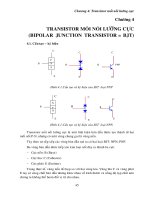
Lecture 7: Bipolar Junction Transistor
+
BJT Design
• Important features of a well-designed BJT
(large β ):
– Injected minority carriers do not recombine in the
quasi-neutral base region.
– Emitter current is comprised almost entirely of
carriers injected into the base (rather than carriers
injected into the emitter).
Carrier Transport in the Base Region
• Since the width of the quasi-neutral base
region (WB = x2-x1) is much smaller than
the minority-carrier diffusion length, very
few of the carriers injected (from the
emitter) into the base recombine before
they reach the collector-junction
depletion region.
Minority-carrier diffusion current is ~constant
in the quasi-neutral base
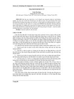
• The minority-carrier concentration at the
edges of the collector-junction depletion
region are ~0.
The B-E junction is forward-biased so electrons
from the emitter are injected across the
B-E junction into the base. These injected
electrons create an excess concentration
of minority carriers in the base. The B-C
junction is reverse biased, so the minority
carrier electron concentration at the edge of
the B-C junction is ideally zero. We expect
the electron concentration in the base to be
like that shown in beside figure.
The large gradient in the electron
concentration means that electrons injected
from the emitter will diffuse across the base
region into the B-C space charge region.
where the electric field will sweep the
electrons into the collector. We want as many
electrons as possible to reach the collector
without recombining with any majority
carrier holes in the base. For this reason, the
width of the base needs to be small
compared with the minority carrier diffusion
length.
Diffusion current reminder
• Linear concentration profile
constant diffusion current
x
n = P1 − ÷
L
P
J n ,diff
dn
= − qDn
dx
P
= qD p
L
Collector Current
P −0
dn( x )
I C = AE qDn
= AE qDn
dx
WB −0
AE qDn ni2
IC =
N BWB
VBE
−1 ÷
exp
VT
VBE
AE qDn ni2
I C ≅ I S exp
where I S =
VT
N BWB
• The equation above shows that the BJT is
indeed a voltage-dependent current source;
thus it can be used as an amplifier.
Emitter Current
• Applying Kirchhoff’s Current Law to the BJT,
we can easily find the emitter current.
1
I E = I C + I B = I C 1 +
β
Summary of BJT Currents
IC
IB
VBE
= I S exp
VT
1
VBE
= I S exp
β
VT
β +1
VBE
IE =
I S exp
β
VT
β
α≡
β +1