RADAR instruction manual JMA 7710 7725
Bạn đang xem bản rút gọn của tài liệu. Xem và tải ngay bản đầy đủ của tài liệu tại đây (10.63 MB, 314 trang )
PREFACE
Thank you very much for purchasing the JRC marine radar equipment, JMA-7710-6 and
JMA-7725-6 / 9.
This equipment is a marine radar equipment designed to obtain safe operation of marine
ships. The equipment consists of a radar signal transceiver unit, a CRT display unit and a
scanner unit as its main units.
The ATA NCA-843 unit is combined as an option with the JMA-7700 radar series.
● Before operating the equipment, be sure to read this instruction manual carefully for
correct operation.
● Maintain this instruction manual so that operators can refer to it at anytime.
Refer to this manual when any inconvenience or defect occur.
● This manual covers the issues related to the operation of the radar and ATA only.
For the issues related to the operation of plotter functions, refer to the following
instruction manual.
NDB-33: Instruction Manual for the Plotter
I
●
Before Operation ●
Pictorial Indication
Various pictorial indications are included in this manual and are
shown on these equipment so that you can operate them safely and
correctly and prevent any danger to you and / or to other persons
and any damage to your property during operation. Such indications
and their meanings are as follows.
Please understand them before you read this manual:
WARNING
This indication is shown where any person is supposed to be in
danger of being killed or seriously injured if this indication is
neglected and these equipment are not operated correctly.
CAUTION
This indication is shown where any person is supposed to be
injured or any property damage is supposed to occur if this
indication is neglected and these equipment are not operated
correctly.
Examples of pictorial indication
Disassembling
prohibited
Disconnect
the power
plug
Electric
shock
The ▲ mark represents CAUTION (including DANGER and
WARNING).
Detailed contents of CAUTION (“Electric Shock” in the example
on the left.)is shown in the mark.
Prohibition
The mark represents prohibition.
Detailed contents of the prohibited action (“Disassembling
Prohibited” in the example on the left) is shown in the mark.
Instruction
The ● mark represents instruction.
Detailed contents of the instruction (“Disconnect the power plug” in
the example on the left) is shown in the mark.
Warning label
There is a warning label on the top cover of the equipment.
Do not try to remove, break or modify the label.
II
●
Cautions to be Used During Operation ●
WARNING
Do not touch the insides of the scanner, transceiver and display unit.
Touching any high voltage area, you will get an electric shock. For maintenance,
inspection and adjustment of internal parts of these equipment, consult with our sales
office or distributor in your district.
Since the scanner radiator rotates, do not approach it.
The scanner may start rotating suddenly, and consequently any person may be struck
and be injured. We recommend you to install the scanner radiator on the roof of the
wheel house, flying bridge, trestle, radar mast or any other high position so that no
person can approach it. When servicing the scanner, set the scanner safety button to
the OFF position.
Install the scanner at any place higher than any person.
If being exposed directly to electric wave at close range, you may suffer adverse
influence.
When approaching the antenna for maintenance or inspection, set the power button of the display unit to the ST-BY
position.
If being exposed directly to electric wave at close range, you may suffer adverse
influence.
CAUTION
Use these radar only as assisting devices for navigation.
Also, the officer should make the final decision for maneuvering by himself.
Use ATA only as an assisting device for navigation.
Also, the officer should make the final decision for maneuvering by himself.
ATA's information such as vector, target value data, alarm, etc. may contain some
errors. Also, targets which cannot be detected with these radar cannot be tracked at
their acquisition points.
III
◆◆◆◆
PRECAUTIONS BEFORE OPERATION ◆◆◆◆
Cautions for high voltage
High voltages from hundreds volts to tens of thousands volts are to be applied to the electronic
equipment such radio and radar devices. You do not face any danger during normal operation, but
sufficient cares are required for maintenance, inspection and adjustment of their internal components.
(Authorized maintenance personnel alone are permitted to implement maintenance, check-ups or
adjustment of internal components.)
High voltages of tens of thousands volts are so dangerous as to bring an instantaneous death from
electric shock, but even voltages of hundreds volts may sometimes lead to a death from electric
shock. To prevent such an accident, make it a rule to turn off the power button, discharge capacitors
with a wire surely earthed on an end and make sure that internal parts are no longer charged before
you touch any parts inside these devices. At the time, wearing dry cotton gloves ensures you further
to prevent such danger. It is also a necessary caution to put one of your hands in the pocket and not
to use your both hands at the same time.
It is also important to select a stable foothold always to prevent additional injuries once you were
shocked by electricity. If you were injured from electric shock, disinfect the burn sufficiently and get
it taken care of promptly.
What to do in case of electric shock
When finding a victim of electric shock, turn off the power source and earth the circuit immediately.
If it is impossible to turn off the circuit, move the victim away promptly using insulators such as dry
wood plate and cloth without touching the victim directly.
In case of electric shock, breathing may stop suddenly if current flows to the respiration center in the
brain. If the shock is not so strong, artificial respiration may recover breathing. When shocked by
electricity, the victim will come to look very bad with weak pulse or without beating, resulting in
unconsciousness and rigidity.
IV
CAUTION
◆◆◆◆◆◆◆◆◆
FIRST AID TREATMENTS ◆◆◆◆◆◆◆◆◆
✩ First-aid treatments
As far as the victim of electric shock is not in dangerous condition, do not move him and practice
artificial respiration on him immediately. Once started, it should be continued rhythmically.
(1) Do not touch the victim confusedly as a result of the accident, but the rescuer may also get an
electric shock.
(2) Turn off the power source calmly and certainly and move the victim away quietly from the
electric line.
(3) Call a physician or ambulance immediately or ask someone to call a doctor.
(4) Lay the victim on his back and loosen his necktie, clothes, belt, etc.
(5) a. Examine the victim’s pulse.
b. Examine his heartbeat bringing your ear close to his heart.
c. Examine his breathing bringing the back of your hand or your face close to his face.
d. Check the size of the pupils of his eyes.
(6) Open the victim’s mouth and take out artificial teeth, cigarette or chewing gum if any. Keep his
mouth open, stretch his tongue and insert a towel or the like in his mouth to prevent the tongue
from suffocating. (If it is hard to open his mouth due to set teeth, open it with a screwdriver and
insert a towel in this mouth.)
(7) Then, close his mouth so that foaming mucus does not accumulate inside.
V
✩ When pulse is beating but breathing has stopped
(1) Tilt the victim’s head back as far as this face looks back. (A pillow may be inserted under his neck.)
(2) Push his jaw upward to open his throat wide (to spread his airway).
(3) Pinch the victim’s nostrils and take a deep breath, block his mouth completely with yours and
blow into his mouth strongly. Take a deep breath again and blow into his mouth. Continue this
10 to 15 times a minute (blocking his nostrils).
(4) Carefully watch that he has recovered his natural breathing and stop practicing artificial respiration.
(5) If it is difficult to open the victim’s mouth, insert a rubber or vinyl tube into one of his nostrils
and blow into it blocking the other nostril and his mouth completely.
(6) When the victim recovers consciousness, he may try to stand up suddenly, but let him lie calmly
and serve him with a cup of hot coffee or tea to keep him warm and quiet. (Never give him
alcoholic drinks.)
Method of mouth-to-mouth respiration by raising head
q
Raise the victim’s head. Support his
forehead with one of your hand and his
neck with the other hand. → q
When you tilt his head backward, the
victim, in most cases, opens his mouth to
the air. This makes mouth-to-mouth
respiration easy.
w
Cover his mouth as widely as possible
with yours and press your cheek against
his nose → w , or, pinch his nostrils
with your fingers to prevent air from
leaking. → e
e
Blow into his lungs.
Continue blowing into his mouth until his
breast swells. Blow into his mouth as
quickly as possible for the first 10 times.
Mouth-to-mouth respiration
VI
CAUTION
✩ When both pulse and breathing have stopped
When no pulse has come not to be felt, his pupils are open and no heartbeat is heard, cardiac arrest is
supposed to have occurred and artificial respiration must be performed.
(1) Place your both hands, one hand on the other, on the lower one third area of his breastbone and
compress his breast with your elbows applying your weight on his breast so that it is dented
about 2cm (repeat compressing his breast 50 times or so a minute). (Cardiac massage)
(2) In case of one rescuer,
Repeat cardiac massages about 15 times and blow into his mouth 2 times quickly, and repeat this
combination.
In case of two rescuers,
One person repeats cardiac massages 5 times while the other person blows into his mouth once,
and they shall repeat this combination. (Cardiac massage and mouth-to-mouth respiration)
(3) Examine his pupils and his pulse sometimes. When the both have returned to normal, stop the
artificial respiration, serve him with a cup of coffee or tea and keep him warm and calm while
watching him carefully. Commit the victim to a medial specialist depending on his condition.
To let him recover from the mental shock, it is necessary for persons concerned to understand his
situations and the necessary treatments.
q
w
e
r
Cardiac massage
VII
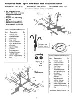
EQUIPMENT APPEARANCE
Scanner Type NKE-1055-6 (6 feet)
Scanner Type NKE-1056-6M (6 feet)
Scanner Type NKE-1056-9M (9 feet)
Display Unit Type NCD-3901-2
VIII
CONTENTS
PREFACE ········································································································ I
Before Operation ··························································································· II
Cautions to be Used During Operation ······················································ III
PRECAUTIONS BEFORE OPERATION ····················································· IV
Cautions for high voltage .......................................................................................................... IV
What to do in case of electric shock .......................................................................................... IV
FIRST AID TREATMENTS ············································································ V
✩ First-aid treatments ..................................................................................................................... V
✩ When pulse is beating but breathing has stopped ...................................................................... VI
✩ When both pulse and breathing have stopped .......................................................................... VII
EQUIPMENT APPEARANCE ···································································· VIII
GLOSSARY ································································································ XVI
1. GENERAL AND EQUIPMENT COMPOSITION
1.1 Functions ···························································································1-1
1.1.1
1.2
1.3
1.4
1.5
1.6
Functions of This Equipment .......................................................................................... 1-1
1.1.1.1 Functions of Radar .......................................................................................... 1-1
1.1.1.2 Functions of ATA (Option) ............................................................................. 1-1
Features ·····························································································1-3
Composition ······················································································1-4
Configuration ·····················································································1-5
General System Diagram ································································1-10
Concept of Collision Avoidance Measures
(Explanatory Notes) ········································································1-14
2. NAMES AND FUNCTIONS OF CONTROL PANEL
SWITCHES AND MENU COMPOSITION
2.1 Names and Functions of Control Panel ··········································2-1
2.2 Menu Composition ··········································································2-13
2.2.1
2.2.2
Menu Selection .............................................................................................................. 2-13
Menu List ...................................................................................................................... 2-14
3. BASIC OPERATION
3.1 Flow of Operation ··············································································3-1
3.1.1
3.1.2
3.1.3
Turning Power on and Starting the System ..................................................................... 3-2
Degauss ........................................................................................................................... 3-3
Tuning ............................................................................................................................. 3-3
IX
3.1.4
3.1.5
3.1.6
Observation and Video Adjustment ................................................................................ 3-4
Data Acquisition and Measurement ................................................................................ 3-4
Ending Operation and Stopping the System .................................................................... 3-4
3.2 Preparation ························································································3-5
3.2.1
3.2.2
3.2.3
3.2.4
3.2.5
3.2.6
3.2.7
3.2.8
3.2.9
3.2.10
3.2.11
Tuning [TUNE] .............................................................................................................. 3-5
Adjusting Sensitivity [GAIN] ......................................................................................... 3-5
Adjusting CRT Brilliance [BRILL] ................................................................................ 3-5
Suppressing Sea Clutter [SEA] ....................................................................................... 3-6
Suppressing Rain and Snow Clutter [RAIN] .................................................................. 3-7
Adjusting Brilliance ........................................................................................................ 3-8
Selecting DAY / NIGHT Modes [DAY / NIGHT] .................................................... 3-9
Setting Color .................................................................................................................. 3-10
3.2.8.1 Background Color ........................................................................................ 3-11
3.2.8.2 Setting Radar Video and Trails Color .......................................................... 3-12
Rejecting Radar Interference ......................................................................................... 3-13
Adjusting Control Panel Brilliance [PANEL] ······························································· 3-13
Stabilization ··················································································································· 3-14
3.3 Basic Operation ···············································································3-15
3.3.1
3.3.2
3.3.3
3.3.4
3.3.5
3.3.6
3.3.7
Using Trackball to Move Cursor "+" ............................................................................ 3-15
Using EBL (Electronic Cursor) [EBL1 / EBL2] ......................................................... 3-15
Selecting Range Scales [RANGE] ................................................................................ 3-18
Selecting Pulse Width [PL] ........................................................................................... 3-18
Disabling Ship's Head Marker [HL OFF] ..................................................................... 3-18
Using Parallel Index Line .............................................................................................. 3-19
Selecting Presentation Mode [PRESENTATION MODE] ........................................... 3-21
3.3.8
Selecting True Motion / Relative Motion Display Modes
[TM / RM] [TM RST] ................................................................................................. 3-22
Changing Own Ship Display Position [OFF CENT] .................................................... 3-24
Displaying Other Ship's Trails [TRAILS] ····································································· 3-25
Displaying Fixed Range Ring [RR] ·············································································· 3-26
Displaying Variable Range Markers [VRM1 / VRM2] ·············································· 3-26
Using Alarm [GZ MENU] ···························································································· 3-28
Stopping Alarm ············································································································· 3-31
Setting Alarm Sound Level ··························································································· 3-32
Enhancing Target ·········································································································· 3-33
Setting Cross Cursor Length and Fixing Cursor Position ············································· 3-34
Displaying Ship's Stern Marker ····················································································· 3-36
Setting Range Unit in KM ····························································································· 3-37
Displaying Video Processing Screen ············································································ 3-39
Zooming Display ··········································································································· 3-41
Selecting Display Mode [MAP] ···················································································· 3-42
Using Electoronic Plot (EPA) ....................................................................................... 3-43
3.3.23.1 Plotting Target .............................................................................................. 3-43
3.3.23.2 Modifying Plot ............................................................................................. 3-44
3.3.23.3 Deleting Plot ................................................................................................. 3-44
3.3.9
3.3.10
3.3.11
3.3.12
3.3.13
3.3.14
3.3.15
3.3.16
3.3.17
3.3.18
3.3.19
3.3.20
3.3.21
3.3.22
3.3.23
X
3.3.24
3.3.25
3.3.26
3.3.23.4 Displaying Plot Numerical Data ................................................................... 3-45
3.3.23.5 Plot Symbol .................................................................................................. 3-46
3.3.23.6 Setting Vector Display ................................................................................. 3-47
3.3.23.7 Setting Vector Time ..................................................................................... 3-48
3.3.23.8 Displaying / Clearing Plot No. ................................................................... 3-49
3.3.23.9 Setting CPA / TCPA .................................................................................. 3-50
3.3.23.10 Turning Alarm Sound On / Off .................................................................. 3-52
3.3.23.11 Displaying / Clearing CPA Ring ................................................................ 3-53
Displaying Date and Time ............................................................................................. 3-54
Displaying the Plain Radar Screen ................................................................................ 3-55
Operation of the Performance Monitor ......................................................................... 3-57
3.4 Using Function Key [FUNC] ···························································3-62
3.4.1
3.4.2
3.4.3
3.4.4
Overview ....................................................................................................................... 3-62
Operation Method .......................................................................................................... 3-62
Function Setting Items ................................................................................................... 3-63
Operation Outline of the Function Setting Items .......................................................... 3-64
3.5 Displaying the Chart ·······································································3-75
3.5.1
3.5.2
3.5.3
3.5.4
Displaying the Shoreline ROM Card Made by JRC ..................................................... 3-75
Displaying the ERC Card .............................................................................................. 3-76
Displaying the JRC Chart .............................................................................................. 3-77
Displaying the Contour of the Shoreline ROM Card by JRC ....................................... 3-78
3.6 Displaying Own Ship Track ····························································3-79
3.6.1
3.6.2
3.6.3
3.6.4
3.6.5
3.6.6
Changing Track Color [When equipped with the plotter] ............................................. 3-79
Selecting Track Storing Interval .................................................................................... 3-79
Stopping Track Storing ................................................................................................. 3-81
Deleting Track by Color (Using the [COLOR] Control) .............................................. 3-83
Deleting Track by Color (Using Menu) ........................................................................ 3-85
Displaying or Hiding Track by Color ............................................................................ 3-87
3.7 Displaying Navigation Information ················································3-89
3.7.1
3.7.2
3.7.3
3.7.4
3.7.5
3.7.6
3.7.7
Creating the Navigation Information (Navigation Lines) ............................................. 3-89
Creating the Navigation Information (Coast Lines and Contour Lines) ....................... 3-92
Creating/Deleting the Navigation Information (Navigation Marks) ............................. 3-93
Turning On or Off Display of Destindtion Marks, Number and Comments ................ 3-94
Turning On or Off Display of Marks and Lines by Specifying Color or Shapes .......... 3-95
Deleting a Mark or Line by Specifying a Color or Shape ............................................. 3-96
Displaying Geodetic Datum .......................................................................................... 3-97
4. MEASUREMENT
4.1 Measurement with Trackball ····························································4-1
4.2 Measurement with Fixed Range Rings ············································4-2
4.3 Measurement with Electronic Cursor
and Variable Range Marker ······························································4-3
4.4 Measurement between Two Optional Points of Target ··················4-4
XI
5. OPERATIONS OF ATA (OPTION)
5.1 Initialization ························································································5-2
5.1.1
5.1.2
5.1.3
Setting Collision Judgment Conditions : SAFE LIMIT ................................................. 5-2
Automatically Set Mode (at Activation) ......................................................................... 5-7
Setting a Range Scale ...................................................................................................... 5-7
5.2 Display Mode ·····················································································5-8
5.2.1
5.2.2
Setting the Motion Display Mode [TM / RM] .............................................................. 5-8
Setting the Bearing Display Mode [AZI MODE] ........................................................... 5-8
5.3 Target Acquisition ·············································································5-9
5.3.1
5.3.2
5.3.3
Automatic Acquisition .................................................................................................... 5-9
Manual Acquisition ....................................................................................................... 5-10
Setting / Deleting a Target Number ............................................................................ 5-10
5.4 Displaying the ATA Data ·································································5-11
5.4.1
5.4.2
Vector Display ............................................................................................................... 5-11
Past Position Display ..................................................................................................... 5-15
5.5 Data Reading ···················································································5-18
5.5.1
5.5.2
Types of Data Readouts to be Displayed ...................................................................... 5-18
Displaying Method of Numerical Data Readouts [TGT DATA] ................................. 5-19
5.6 Alarm Display ··················································································5-20
5.6.1
5.6.2
5.6.3
5.6.4
Dangerous Target Alarm : CPA / TCPA .................................................................... 5-20
Guard Zone Alarm ......................................................................................................... 5-21
Lost Target Alarm ......................................................................................................... 5-22
Stopping Alarm ............................................................................................................. 5-22
5.7 Erasing an Unnecessary Target ·····················································5-23
5.7.1
5.7.2
Erasing a Target per Target ........................................................................................... 5-23
Erasing All Targets ........................................................................................................ 5-23
5.8 Adjusting Intensity ··········································································5-24
5.9 Function Check ···············································································5-25
5.9.1
5.9.2
5.9.3
Vector Constant Setting (ATA) ..................................................................................... 5-25
Video Level Setting ....................................................................................................... 5-26
Checking the ATA Operation ........................................................................................ 5-29
5.10 Target Past Track ············································································5-31
5.10.1
5.10.2
5.10.3
5.10.4
5.10.5
5.10.6
5.10.7
5.10.8
5.10.9
Setting Target Past Track Function ............................................................................... 5-31
Specifying Target Past Track ........................................................................................ 5-32
Setting Target Past Track Color .................................................................................... 5-33
Setting Target Past Track Display ................................................................................. 5-34
Setting the Storage Interval ........................................................................................... 5-35
Erasing the Storage of Target Past Track by Specifying a Color .................................. 5-36
Erasing the Storage of Target Past Track by Specifying a Number .............................. 5-37
Reading Target Past Track from Card 2 ........................................................................ 5-38
Writing Target Past Track to Card 2 ............................................................................. 5-39
5.11 Turning ON and OFF the ATA Display ··········································5-40
5.12 Turning On and OFF the Alarm Sound of Dangerous and
Lost Targets ·····················································································5-41
XII
5.13 Simulation
(Checking the ATA according to a Pseudo Target) ·····················5-42
6. TRUE AND FALSE ECHOES ON DISPLAY
6.1
6.2
6.3
6.4
6.5
Radar Line-of-sight Range ·······························································6-1
Strength of Reflection from Target ··················································6-3
Sea Clutters ·······················································································6-3
False Echoes ·····················································································6-3
Display of Radar Transponder ·························································6-6
7. MAINTENANCE
7.1 Routine Maintenance ········································································7-1
7.1.1
Cleaning ........................................................................................................................... 7-1
7.1.1.1 Cleaning of the Radar ..................................................................................... 7-1
7.1.1.2 Cleaning of the ATA ...................................................................................... 7-1
7.2 Maintenance of Each Unit ·································································7-2
7.2.1
7.2.2
Scanner Unit NKE-1055 / 1056 .................................................................................... 7-2
Display Unit NCD-3901-2 .............................................................................................. 7-4
8. COUNTERMEASURES FOR TROUBLE
AND ADJUSTMENT
8.1 Function Check ·················································································8-1
8.1.1
8.1.2
Function Check ................................................................................................................ 8-1
Testing Functions with Menu .......................................................................................... 8-1
8.1.2.1 Memory Test .................................................................................................. 8-2
8.1.2.2 Key Switch Test ............................................................................................. 8-3
8.1.2.3 Sensor Test ..................................................................................................... 8-4
8.1.2.4 Line Test ......................................................................................................... 8-4
8.1.2.5 ATA Status ..................................................................................................... 8-5
8.1.2.6 ROM Version ................................................................................................. 8-5
8.1.2.7 Error Logging ................................................................................................. 8-6
8.1.2.8 Magnetron Current, Running and Transmission Time ................................... 8-7
8.2 Failure Check ·····················································································8-8
8.3 Troubleshooting ··············································································8-10
8.3.1
8.3.2
Troubleshooting for the Radar ...................................................................................... 8-10
ATA Traubleshooting .................................................................................................... 8-12
8.4 Replacement of Major Parts ···························································8-14
8.5 Adjustment and Setting ··································································8-19
8.5.1
8.5.2
NSK Unit Adjustment ................................................................................................... 8-19
Adjustment and Setting at Installation .......................................................................... 8-22
8.5.2.1 Adjusting Tuning .......................................................................................... 8-22
8.5.2.2 Adjusting Bearing ......................................................................................... 8-23
8.5.2.3 Adjusting Range ........................................................................................... 8-24
8.5.2.4 Setting Antenna Height ................................................................................ 8-25
XIII
8.5.3
8.5.4
8.5.5
8.5.6
8.5.7
Various Setting .............................................................................................................. 8-26
8.5.3.1 Setting Own Ship Speed Equipment ............................................................ 8-26
8.5.3.2 Setting True Bearing .................................................................................... 8-27
8.5.3.3 Setting Ship Speed ........................................................................................ 8-28
8.5.3.4 Setting Drift .................................................................................................. 8-29
8.5.3.5 Setting PRF ................................................................................................... 8-30
8.5.3.6 Setting Transmission Repetition Frequency ................................................. 8-31
8.5.3.7 Connecting Navigation Equipment .............................................................. 8-32
8.5.3.8 Adjustment of the Performance Monitor Operation ..................................... 8-34
GPS Initial Setting / Receiving Status ........................................................................ 8-35
8.5.4.1 GPS Initial Setting ........................................................................................ 8-35
8.5.4.2 Checking GPS Receiving Status .................................................................. 8-39
Setting DGPS / Checking DGPS Receiving Status .................................................... 8-41
8.5.5.1 Setting DGPS ............................................................................................... 8-41
8.5.5.2 Checking DGPS Receiving Status ............................................................... 8-43
Maintenance Menu ........................................................................................................ 8-44
8.5.6.1 Antenna Switch ............................................................................................ 8-44
8.5.6.2 Partial Master Reset ...................................................................................... 8-45
8.5.6.3 Total Master Reset ........................................................................................ 8-45
8.5.6.4 Internal Setting to Card 2 ............................................................................. 8-45
8.5.6.5 Card 2 to Internal Setting ............................................................................. 8-46
8.5.6.6 User Memory ................................................................................................ 8-47
8.5.6.7 Restoring User Memory ............................................................................... 8-47
Adjusting Position to Chart ........................................................................................... 8-49
8.5.7.1 Adjusting Video and Chart Using Trackball (R+P Mode) ........................... 8-49
8.5.7.2 Adjusting Video and Chart Position by Entering Adjustment Value
(R+P and Plotter Modes) .............................................................................. 8-50
8.5.7.3 Adjusting Position by Changing Latitude / Longitude Information
from GPS (R+P and Plotter Modes) ............................................................. 8-51
8.5.7.4 Adjusting Position by Fixing Own Ship at Screen Center ........................... 8-52
9. AFTER-SALES SERVICE
10. DISPOSAL
10.1 Equipment Disposal ········································································10-1
10.2 Disposal of Used Batteries ·····························································10-2
10.3 Disposal of Used Magnetron ··························································10-3
11. SPECIFICATION
11.1 General Specification
JMA-7710-6 / JMA-7725-6 / JMA-7725-9····································11-1
11.2 Scanner Unit NKE-1055-6 ······························································11-2
11.3 Scanner Unit NKE-1056-6M / 9M ·················································11-3
11.4 Display Unit NCD-3901-2 ································································11-4
XIV
11.5 ATA NCA-843 (Optional) ································································11-7
11.6 Inputable Signal ··············································································11-7
11.7 Outputable Signal ···········································································11-8
11.8 Standard Equipment Configuration ··············································11-8
11.9 Installing Clearance between Equipment ·····································11-8
11.10Others (Optional) ············································································11-8
APPENDIX
Attached Figures
Appendix 1
Appendix 2
Appendix 3
Appendix 4
Appendix 5
Appendix 6
Appendix 7
Appendix 8
Appendix 9
Appendix 10
Radar System Circuit Code List
Circuit Diagram of Radar Type JMA-7710-6 and JMA-7725-6 / 9
Terminal Board Connection Diagram of Radar Type JMA-7710-6
Terminal Board Connection Diagram of Radar Type JMA-7725-6 / 9
Primary Power Supply System Diagram of Radar Type JMA-7710-6
and JMA-7725-6 / 9
Internal Connection Diagram of Scanner Unit Type NKE-1055
Internal Connection Diagram of Scanner Unit Type NKE-1056
Internal Connection Diagram of Display Unit Type NCD-3901-2
Power Supply Connection Diagram of Display Unit Type NCD-3901-2
NSK Log Selection Switches of Display Unit Type NCD-3901-2
Appendix 11 Setting Table of the Speed Log Select Switches of Display Unit Type NCD-3901-2
Appendix 12 Setting Table of the Gyro Compass and Gyro Select Switches of Display Unit Type
NCD-3901-2
XV
GLOSSARY
This section explains common maritime terms and the terms used for this equipment.
ATA (Automatic Tracking Aid) :
Supporting equipment for automatically preventing clash.
Fast Time Constant (FTC) :
Rain and snow clutter suppression.
Sensitivity Time Control (STC) :
Sea surface clutter suppression.
Bearing :
Direction
COG :
Course over Ground
CPA/TCPA :
Closest point of approach and time to closest point of approach
limit as defined by the observer to give warning when a tracked
target or targets will close to within these limits from own
ship
CUP (Course-UP) :
An azimuth stabilized display in which a line connecting the
centre of own ship with the top of the display is own ship's
intended course
EBL (Electric Bearing Line) :
Electric bearing line centering the position of the own ship.
GPS (Global Positioning System) :
Internationally-used positioning system.
Ground stabilization :
A mode of display whereby own ship and all targets are
referenced to the ground using ground track or set and drift
inputs
Guard zone :
A zone in which an alarm is given when a target is detected
Heading :
The direction in which the bows of a ship are pointing
expressed as an angular displacement from north
HL :
Heading Line
HUP (Head-UP) :
Display mode in which the top of the screen corresponds to
the ship's head maker.
IMO :
International Maritime Organization
IR :
Interference Rejector
NM :
Nautical Mile (1 nm = 1,852 m)
NSK :
Gyro compass and log interface
NUP (North-UP) :
An azimuth stabilized display in which a line connecting the
centre of own ship with the top of the display is north true
bearing
Own track :
Automatic track display function.
Range ring :
Fixed range ring.
RM (Relative Motion) :
The combination of relative course and relative speed
RM display :
A display on which the position of own ship remains fixed
and all targets move relative to own ship
Relative bearing :
The direction of a target from own ship expressed as an angular
displacement from own ship's heading
XVI
Relative course :
The direction of motion of a target relative to own ship's
position expressed as an angular displacement from north. It
is deduced from a number of measurements of target range
and bearing on own ship's radar
Relative speed :
The speed of a target relative to own ship's position. It is
deduced from a number of measurements of target range and
bearing on own ship's radar
Relative vector :
The predicted movement of a target relative to own ship
Scan CORR :
Target emphatic processing function.
Scanner :
Antenna unit.
Sea stabilization :
A mode of display whereby own ship and all targets are
referenced to the sea, using gyro heading and single axis log
water speed inputs
Target ENH :
Target enhancing function.
TM (True Motion) :
The combination of true course and true speed
TM display :
A display across which own ship and each target moves with
its own true motion
VRM :
Variable Range Marker
Trails :
Tracks displayed by the radar echoes of targets in the form of
a synthetic afterglow. The trails may be either relative or true.
The true trails may be sea or ground stabilized
SOG :
Speed over Ground
True bearing :
The direction of a target from own ship or from another target
expressed as an angular displacement from north
True course :
The true direction of motion of a target expressed as an angular
displacement from north. It is obtained by a vector
combination of target relative motion and own ship's true
motion
True speed :
The speed of a target obtained by a vector combination of
target relative motion and own ship's true motion
True vector :
The predicted true motion of a target as a result of own ship's
direction and speed input. The true vector may be either
displayed with reference to the water or to the ground
Performance monitor :
Additional equipment for monitoring transmission power and
receiving sensitivity.
Floating EBL (Electric Bearing Line) : Electric bearing line centering a certain point.
XVII
XVIII
1
GENERAL AND EQUIPMENT COMPOSITION
2
NAMES AND FUNCTIONS OF CONTROL
2
PANEL SWITCHES AND MENU COMPOSITION
3
BASIC OPERATION
3
4
MEASUREMENT
4
5
OPERATIONS OF ATA (OPTION)
5
6
TRUE AND FALSE ECHOES ON DISPLAY
6
7
MAINTENANCE
7
8
COUNTERMEASURES FOR TROUBLE
AND ADJUSTMENT
8
9
AFTER-SALES SERVICE
9
10
DISPOSAL
10
11
SPECIFICATION
11
APPENDIX
APPENDIX
1
1
GENERAL AND
EQUIPMENT
COMPOSITION
1.1
1.2
1.3
1.4
1.5
1.6
Functions······························································1-1
Features ································································1-3
Composition ·························································1-4
Configuration ·······················································1-5
General System Diagram ··································1-10
Concept of Collision Avoidance Measures
(Explanotory Notes) ··········································1-14
1.1
Functions
This equipment is a high performance, high quality, highly reliable and totally-large-scale-integrated
(excluding special electronic tubes) radar composed of a scanner, a transceiver and a display unit with a high
resolution color CRT which adopts the raster scan method.
1.1.1 Functions of This Equipment
1.1.1.1 Functions of Radar
The JMA-7700 series color radar is designed in accordance with IMO (International Maritime Organization)
specifications based on international standards. The major functions include target detecting color display,
sea, rain or snow clutter restraint, sensitivity adjustment, interference rejection, distance and bearing
measurement using a trackball, fixed and variable distance markers and an electronic cursor as well as
Standard equipment ATA (manual and automatic target acquisition and vector, tracking and warning display),
a plotter (own ship tracking and coastal line display) and an optional simple plotter (make and line display as
well as target and course setting).
1.1.1.2 Functions of ATA (Option)
This system, on which a radar is used as a sensor, can be outlined as follows by function:
[I]
First Stage : Target Detection from Radar Information
This work corresponds to plotting targets by hand on the radar screen. Assume that a ship is
approaching the own ship. You can catch the ship on the radar. Signals from the ship are processed
with the data processor and are transferred to the computer as signals of bearing and range related to
the own ship. In this stage, the system has the functions to quantize radar information, to reject
noises, to eliminate any information other than ship information and to transfer necessary position
data of ships to the computer.
[II]
Second Stage : Target Tracking
Targets are plotted at intervals of 3 or 6 minutes with the radar, but tracking on this system is to plot
them electrically at intervals of fixed times. This means to compare target position data to be detected
every moment with those detected previously so as to check if they are of the same target and also to
save data of the target in its file so as to calculate changes of position data of the target.
[III] Third Stage : Judgement of Existence of Ship in Danger of Collision
In this stage, the system calculates speeds and courses of a target ship from ever-changing position
data of the target ship obtained in the previous stage so as to judge existence of any danger of collision.
After the calculation, the system can easily calculate the closes point of approach to the own ship
(CPA = Closest Point of Approach) and the time required to reach the CPA (TCPA = Time to CPA).
Both the CPA and the TCPA are compared with the value previously set according to the situations
of the own ship so as to judge existence of any danger of collision.
1–1
1.1
1
[IV] Fourth Stage : Indication
The above information must be informed to the officer maneuvering the own ship. A variety of
indicating methods are available including cathode ray tube and numerical indicator, and various
data are available.
This system indicates unprocessed video, vectors (to be selected from true vector and relative vector)
of other ships and identification marks of danger ship or safe ship for these ships on the usual radar
scope. When the target ship is a danger one, the system will sound an alarm and turns on the alarm
lamp to alert the officer.
1–2