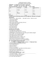
Tăng cường ảnh chụp với hệ thống CT
Bạn đang xem bản rút gọn của tài liệu. Xem và tải ngay bản đầy đủ của tài liệu tại đây (2.07 MB, 8 trang )
Dual Energy Radiography
Dual Energy Imaging
with Dual Source CT Systems
Rainer Raupach, PhD
Siemens Healthcare
Radiograph
Bone image
2 energies
Tissue image
2 materials
Armato SG III. Experimental Lung Research. 2004;30 (suppl 1):72-77.
kV Switching with SOMATOM DRH – in the 80s
Calculation of material selective images:
Calcium and soft tissue
Principle of Dual Energy CT
Data acquisition with different X-ray spectra: 80 kV / 140 kV
Standard image
Rapid kVp switching
Mean Energy:
Calcium image
56 kV
76 kV
Basis material
decomposition
Low kVp
Tube 1
Soft tissue image
Tube 2
High kVp
Attenuation profiles
Different mean energies of the X-ray quanta
W. Kalender: Vertebral Bone Mineral Analysis, Radiology 164:419-423 (1987)
1
SOMATOM Definition
The World’s First Dual Source CT
Principle of Dual Energy CT
Many materials show different attenuation at different mean energies
Faster than Every Beating Heart
1.0E+02
gated mode / same kV
high temporal resolution (80ms)
Cardiac imaging
Iodine
Bone
Attenuation
56 kV 76 kV
1.0E+01
Large increase
One-Stop Diagnosis in Acute Care
non gated mode / same kV
low temporal resolution
Obese patients, low kV scanning
1.0E+00
Small increase
1.0E-01
10
30
50
70
90
Energy / keV
110
130
Beyond Visualization with Dual Energy
150
different kV (gated and non-gated)
Reason: different attenuation mechanisms (Compton vs photo effect)
“Contrast Enhanced Viewing” using Dual Energy
Information in Addition to Simple Image Mixing
Spectra of Dual Energy Applications
Basic application: Enhanced viewing, contrast optimization
Contrast enhanced studies: Iodine has much higher contrast at 80 kV
Non-linear, attenuation-dependent blending of the images
combines benefits of 80 kV (high contrast) and mixed data (low noise)
Direct Angio
Lung PBV
Virtual Unenhanced
Lung Vessels
140 kV
Hardplaque Display
Heart PBV
Musculoskeletal
Gout
Calculi Characterization
Lung Nodules*
*510(k) approved
80 kV
Blending
Brain Hemorrhage
Xenon*
Courtesy of CIC Mayo Clinic Rochester, MN, USA
2
syngo Dual Energy
Direct subtraction of bone
syngo Dual Energy
Direct subtraction of bone
Modified 2-material decomposition: Separation of two materials
Assume mixture of blood + iodine (unknown density)
and bone marrow + bone (unknown density)
Separation line
600
Iodine pixels
Bone
550 HU
HU at 80 kV
500
400
Automatic bone removal without user interaction
Clinical benefits in complicated anatomical situations:
Base of the skull
Carotid arteries
Vertebral arteries
Peripheral runoffs
Bone pixels
Blood+iodine
80kV
Marrow+bone
300
Iodine
425 HU
Modified 2-material decomposition: Separation of bone and Iodine
200
100
Soft
tissue
0
-100
-100
Bone
400 HU
Blood
Marrow
Iodine
250 HU
140kV
0
100
200
300
HU at 140 kV
400
500
600
syngoDualEnergy
Differentiation between hard plaques and contrast agent
Courtesy of Prof. Pasovic,
University Hospital of Krakow,
Poland
Image Based Methods
Modified 2-material decomposition: Characterization of kidney stones
Urine + calcified stones / uric acid stones
HU at 80 kV
high Z
low Z
HU at 140 kV
Courtesy of CCM Monaco, Monaco
3
syngo Dual Energy Musculoskeletal
Visualization of tendons
syngo Dual Energy
Visualization of Tendons: Tibialis posterior tendon rupture
SOMATOM
Definition
World’s first DSCT
Spatial Res. 0.33 mm
Rotation 0.5 sec
Scan time: 4 s
Scan length: 133 mm
140/80 kV
Eff mAs 80/150
Spiral Dual Energy
Courtesy of University Medical Center Grosshadern / Munich, Germany
Courtesy of University Medical Center Grosshadern / Munich, Germany
Applications of Dual Energy CT
Gout: Application
Three material decomposition: quantification of iodine – iodine image
HU at 80 kV
Iodine
Iodine content
65
Tissue
0
-100
Fat
-90
0
60
HU at 140 kV
Vancouver General Hospital, Canada
Removal of iodine from the image: virtual non-contrast image
4
Image Based Methods
Applications of Dual Energy CT
Most promising application: 3-material decomposition
Calculation of a virtual non-contrast image, Iodine quantification
Virtual non-contrast image and iodine image:
Characterization of liver / kidney / lung tumors
Solve ambiguity: low fat content or iodine-uptake
Quantify iodine-uptake in the tumor and at the tumor surface
Differentiation benign - malignant
Monitoring of therapy response
Mixed image
Mixed image 80kV+140kV
Virtual unenhanced image
VNC image
Iodine image
Iodine overlay image
+
Courtesy of University Hospital of Munich - Grosshadern / Munich, Germany
SOMATOM Definition Flash
Latest Generation of Dual Energy CT
Applications of Dual Energy CT
Quantification of iodine to visualize perfusion defects in the lung
Avoids registration problems of non-dual energy subtraction methods
80/140kV Mixed Image
Iodine Image
Mixed image + iodine overlay
System Design
Two X-ray tubes at 95°,
each with 100 kW
33 cm
Two 128-slice detectors,
each with 64x0.6mm collimation
and z-flying focal spot
Embolus
SFOV A/B-detector:
50/33 cm
0.28 s gantry rotation time
75 ms temporal resolution
Courtesy of Prof. J and M Remy, Hopital Calmette, Lille, France
5
Dual Energy Imaging with Tin Filtration
‘Definition’ vs. ‘Definition Flash’: Improved DE Signal
SOMATOM Definition Flash
Single dose Dual Energy
Mixed Images
80 kV
140 kV
overlap
VNC
Iodine
DE Images
Definition
Conventional DE
DSCT
Dual Energy
DE with
Selective
Photon Shield
80 kV
140 kV with SPS
overlap
Tissue characterization
Improved DE contrast
Dose-neutral compared to a
single 120 kV scan
Definition Flash
DE with Selective Photon Shield
SD and dose: equal
SD: -25%
Images acquired and processed in collaboration with CIC Mayo Clinic Rochester, USA
SOMATOM Definition Flash
Impact of the Selective Photon Shield
SOMATOM Definition Flash
Image
Dual
Energy Whole Body CTA: 100/140Sn kV @ 0.6mm
Dose neutral DE: comparison of 120 kV and 100 kV/140 kV+0.4 mm Sn
Single DE CT Scan
120kV, 500mA
100/140Sn kV, 500mA
noise: 14.1 HU
noise: 13.9 HU
iodine: 329.0 HU
iodine: 330.0 HU
bone: 334.8 HU
bone: 335.3 HU
Courtesy of Friedrich-Alexander University Erlangen-Nuremberg - Institute of Medical Physics / Erlangen, Germany
6
Dual Energy CT
New Application Classes
Are there alternative approaches?
40 keV
Sequential acquisition at 80 kV and 140 kV with single source CT
Registration problems (heart/lung motion, varying contrast density)
Fast kVp-switching during the scan with single source CT
Inadequate power at low kV
Unequal noise for low and high kV data
Measurement of
Lung Nodule
enhancement
courtesy of ASAN Medical
Center, Seoul, Korea
Measurement of
Xenon Concentration
190 keV
Spectral sensitive „sandwich“ detectors
Inferior spectral separation
courtesy of ASAN Medical
Center, Seoul, Korea
Mono-energetic
imaging
courtesy of Klinikum Großhadern,
Munich, Germany
Dual Energy CT
Evaluation of alternative approaches
Quantum counting
Paralysis at high flux rate
Spectral overlap by fluorescence and pile-up
Dual Energy CT
Evaluation of alternative approaches
dual−source (tin filter)
dual−source (std. filter)
sequential kVp
dual−layer (GOS)
dual−layer (CsI)
dual−layer (ZnSe)
quantum counting (CZT)
1.6
1.4
DE Performance
@ equal dose
relative DEC²
1.2
1
0.8
0.6
0.4
Dose
0.2
0
15
20
25
30
35
phantom diameter [cm]
40
45
S. Kappler et al., Dual-energy performance of dual-kVp in comparison to dual-layer and quantum-counting CT
system concepts, Proceedings of the SPIE Medical Imaging Conference, Volume 7258, pp. 725842 (2009)
7
Thank you!
8