Etabs concrete frame design manual
Bạn đang xem bản rút gọn của tài liệu. Xem và tải ngay bản đầy đủ của tài liệu tại đây (1.23 MB, 204 trang )
Concrete Frame
Design Manual
ETABS®
Integrated
Three-Dimensional
Static and Dynamic Analysis and Design
of
Building Systems
CONCRETE FRAME DESIGN MANUAL
COMPUTERS &
STRUCTURES
INC.
R
Computers and Structures, Inc.
Berkeley, California, USA
Version 7.0
July 2000
COPYRIGHT
The computer program ETABS and all associated documentation are
proprietary and copyrighted products. Worldwide rights of ownership
rest with Computers and Structures, Inc. Unlicensed use of the program
or reproduction of the documentation in any form, without prior written
authorization from Computers and Structures, Inc., is explicitly prohibited.
Further information and copies of this documentation may be obtained
from:
Computers and Structures, Inc.
1995 University Avenue
Berkeley, California 94704 USA
Tel: (510) 845-2177
Fax: (510) 845-4096
E-mail:
Web: www.csiberkeley.com
© Copyright Computers and Structures, Inc., 1978–2000.
The CSI Logo is a registered trademark of Computers and Structures, Inc.
ETABS is a registered trademark of Computers and Structures, Inc.
DISCLAIMER
CONSIDERABLE TIME, EFFORT AND EXPENSE HAVE GONE
INTO THE DEVELOPMENT AND DOCUMENTATION OF ETABS.
THE PROGRAM HAS BEEN THOROUGHLY TESTED AND USED.
IN USING THE PROGRAM, HOWEVER, THE USER ACCEPTS
AND UNDERSTANDS THAT NO WARRANTY IS EXPRESSED OR
IMPLIED BY THE DEVELOPERS OR THE DISTRIBUTORS ON
THE ACCURACY OR THE RELIABILITY OF THE PROGRAM.
THIS PROGRAM IS A VERY PRACTICAL TOOL FOR THE DESIGN OF REINFORCED CONCRETE STRUCTURES. HOWEVER,
THE USER MUST THOROUGHLY READ THE MANUAL AND
CLEARLY RECOGNIZE THE ASPECTS OF REINFORCED CONCRETE DESIGN THAT THE PROGRAM ALGORITHMS DO NOT
ADDRESS.
THE USER MUST EXPLICITLY UNDERSTAND THE ASSUMPTIONS OF THE PROGRAM AND MUST INDEPENDENTLY VERIFY THE RESULTS.
Table of Contents
CHAPTER I
Introduction
1
Overview . . . . . . . . . . . . . . . . . . . . . . . . . . . . . . . . . 1
Organization . . . . . . . . . . . . . . . . . . . . . . . . . . . . . . . 2
Recommended Reading . . . . . . . . . . . . . . . . . . . . . . . . . . 3
CHAPTER II
Design Algorithms
5
Design Load Combinations . . . . . . . . . . . . . . . . . . . . . . . . 6
Design and Check Stations . . . . . . . . . . . . . . . . . . . . . . . . 7
Identifying Beams and Columns . . . . . . . . . . . . . . . . . . . . . 8
Design of Beams . . . . . . . . . . . . . . . . . . . . . . . . . . . . . 8
Design of Columns . . . . . . . . . . . . . . . . . . . . . . . . . . . . 9
Design of Joints . . . . . . . . . . . . . . . . . . . . . . . . . . . . 14
Beam/Column Flexural Capacity Ratios . . . . . . . . . . . . . . . . 18
P-, Effects . . . . . . . . . . . . . . . . . . . . . . . . . . . . . . . . 18
Element Unsupported Lengths . . . . . . . . . . . . . . . . . . . . . 19
Special Considerations for Seismic Loads . . . . . . . . . . . . . . . 20
Choice of Input Units . . . . . . . . . . . . . . . . . . . . . . . . . . 21
CHAPTER III Design for ACI 318-99
Design Load Combinations . . . . . . . . . . . . .
Strength Reduction Factors . . . . . . . . . . . . .
Column Design . . . . . . . . . . . . . . . . . . .
Generation of Biaxial Interaction Surfaces . . .
Check Column Capacity . . . . . . . . . . . .
Determine Factored Moments and Forces.
Determine Moment Magnification Factors
23
.
.
.
.
.
.
.
.
.
.
.
.
.
.
.
.
.
.
.
.
.
.
.
.
.
.
.
.
.
.
.
.
.
.
.
.
.
.
.
.
.
.
.
.
.
.
.
.
.
.
.
.
.
.
.
.
.
.
.
.
.
.
.
.
.
.
.
.
.
.
23
26
27
27
29
29
29
i
ETABS Concrete Design Manual
Determine Capacity Ratio . . . . . . . . . . .
Design Column Shear Reinforcement . . . . . . .
Determine Section Forces . . . . . . . . . . .
Determine Concrete Shear Capacity . . . . .
Determine Required Shear Reinforcement . .
Beam Design. . . . . . . . . . . . . . . . . . . . . . .
Design Beam Flexural Reinforcement . . . . . . .
Determine Factored Moments . . . . . . . . .
Determine Required Flexural Reinforcement .
Design Beam Shear Reinforcement. . . . . . . . .
Determine Shear Force and Moment . . . . .
Determine Concrete Shear Capacity . . . . .
Determine Required Shear Reinforcement . .
Design of Joints . . . . . . . . . . . . . . . . . . . .
Determine the Panel Zone Shear Force . . . . . . .
Determine the Effective Area of Joint . . . . . . .
Check Panel Zone Shear Stress . . . . . . . . . . .
Beam/Column Flexural Capacity Ratios . . . . . . . .
.
.
.
.
.
.
.
.
.
.
.
.
.
.
.
.
.
.
.
.
.
.
.
.
.
.
.
.
.
.
.
.
.
.
.
.
.
.
.
.
.
.
.
.
.
.
.
.
.
.
.
.
.
.
.
.
.
.
.
.
.
.
.
.
.
.
.
.
.
.
.
.
.
.
.
.
.
.
.
.
.
.
.
.
.
.
.
.
.
.
.
.
.
.
.
.
.
.
.
.
.
.
.
.
.
.
.
.
.
.
.
.
.
.
.
.
.
.
.
.
.
.
.
.
.
.
.
.
.
.
.
.
.
.
.
.
.
.
.
.
.
.
.
.
CHAPTER IV Design for UBC 97
Design Load Combinations . . . . . . . . . . . . . . .
Strength Reduction Factors . . . . . . . . . . . . . . .
Column Design . . . . . . . . . . . . . . . . . . . . .
Generation of Biaxial Interaction Surfaces . . . . .
Check Column Capacity . . . . . . . . . . . . . .
Determine Factored Moments and Forces. . .
Determine Moment Magnification Factors . .
Determine Capacity Ratio . . . . . . . . . . .
Design Column Shear Reinforcement . . . . . . .
Determine Section Forces . . . . . . . . . . .
Determine Concrete Shear Capacity . . . . .
Determine Required Shear Reinforcement . .
Beam Design. . . . . . . . . . . . . . . . . . . . . . .
Design Beam Flexural Reinforcement . . . . . . .
Determine Factored Moments . . . . . . . . .
Determine Required Flexural Reinforcement .
Design Beam Shear Reinforcement. . . . . . . . .
Determine Shear Force and Moment . . . . .
Determine Concrete Shear Capacity . . . . .
Determine Required Shear Reinforcement . .
Design of Joints . . . . . . . . . . . . . . . . . . . .
Determine the Panel Zone Shear Force . . . . . . .
Determine the Effective Area of Joint . . . . . . .
Check Panel Zone Shear Stress . . . . . . . . . . .
ii
31
32
33
34
36
36
37
37
37
44
44
46
46
46
47
48
48
49
51
.
.
.
.
.
.
.
.
.
.
.
.
.
.
.
.
.
.
.
.
.
.
.
.
.
.
.
.
.
.
.
.
.
.
.
.
.
.
.
.
.
.
.
.
.
.
.
.
.
.
.
.
.
.
.
.
.
.
.
.
.
.
.
.
.
.
.
.
.
.
.
.
.
.
.
.
.
.
.
.
.
.
.
.
.
.
.
.
.
.
.
.
.
.
.
.
.
.
.
.
.
.
.
.
.
.
.
.
.
.
.
.
.
.
.
.
.
.
.
.
.
.
.
.
.
.
.
.
.
.
.
.
.
.
.
.
.
.
.
.
.
.
.
.
.
.
.
.
.
.
.
.
.
.
.
.
.
.
.
.
.
.
.
.
.
.
.
.
.
.
.
.
.
.
.
.
.
.
.
.
.
.
.
.
.
.
.
.
.
.
.
.
54
55
56
56
58
58
58
60
61
62
63
64
66
66
66
67
73
74
75
76
76
77
78
78
Table of Contents
Beam/Column Flexural Capacity Ratios . . . . . . . . . . . . . . . . 78
CHAPTER V Design for CSA-A23.3-94
81
Design Load Combinations . . . . . . . . . . . . . . . . . . . . . . . 84
Strength Reduction Factors . . . . . . . . . . . . . . . . . . . . . . . 84
Column Design . . . . . . . . . . . . . . . . . . . . . . . . . . . . . 85
Generation of Biaxial Interaction Surfaces . . . . . . . . . . . . . 85
Check Column Capacity . . . . . . . . . . . . . . . . . . . . . . 87
Determine Factored Moments and Forces. . . . . . . . . . . 87
Determine Moment Magnification Factors . . . . . . . . . . 87
Determine Capacity Ratio . . . . . . . . . . . . . . . . . . . 90
Design Column Shear Reinforcement . . . . . . . . . . . . . . . 91
Determine Section Forces . . . . . . . . . . . . . . . . . . . 91
Determine Concrete Shear Capacity . . . . . . . . . . . . . 93
Determine Required Shear Reinforcement . . . . . . . . . . 94
Beam Design. . . . . . . . . . . . . . . . . . . . . . . . . . . . . . . 97
Design Beam Flexural Reinforcement . . . . . . . . . . . . . . . 97
Determine Factored Moments . . . . . . . . . . . . . . . . . 97
Determine Required Flexural Reinforcement . . . . . . . . . 98
Design Beam Shear Reinforcement . . . . . . . . . . . . . . . . 105
Determine Shear Force and Moment. . . . . . . . . . . . . 106
Determine Concrete Shear Capacity . . . . . . . . . . . . . 107
Determine Required Shear Reinforcement. . . . . . . . . . 108
CHAPTER VI Design for BS 8110-85 R1989
Design Load Combinations . . . . . . . . . . . . . .
Design Strength . . . . . . . . . . . . . . . . . . . .
Column Design . . . . . . . . . . . . . . . . . . . . .
Generation of Biaxial Interaction Surfaces . . . .
Check Column Capacity. . . . . . . . . . . . . .
Determine Factored Moments and Forces . .
Determine Additional Moments . . . . . . .
Determine Capacity Ratio . . . . . . . . . .
Design Column Shear Reinforcement . . . . . . .
Beam Design . . . . . . . . . . . . . . . . . . . . . .
Design Beam Flexural Reinforcement . . . . . .
Determine Factored Moments . . . . . . . .
Determine Required Flexural Reinforcement
Design Beam Shear Reinforcement . . . . . . . .
CHAPTER VII Design for Eurocode 2
111
.
.
.
.
.
.
.
.
.
.
.
.
.
.
.
.
.
.
.
.
.
.
.
.
.
.
.
.
.
.
.
.
.
.
.
.
.
.
.
.
.
.
.
.
.
.
.
.
.
.
.
.
.
.
.
.
.
.
.
.
.
.
.
.
.
.
.
.
.
.
.
.
.
.
.
.
.
.
.
.
.
.
.
.
.
.
.
.
.
.
.
.
.
.
.
.
.
.
.
.
.
.
.
.
.
.
.
.
.
.
.
.
111
114
114
115
116
117
117
119
120
121
121
122
122
127
129
Design Load Combinations . . . . . . . . . . . . . . . . . . . . . . 129
Design Strength . . . . . . . . . . . . . . . . . . . . . . . . . . . . 132
Column Design . . . . . . . . . . . . . . . . . . . . . . . . . . . . . 133
iii
ETABS Concrete Design Manual
Generation of Biaxial Interaction Surfaces . . . .
Check Column Capacity. . . . . . . . . . . . . .
Determine Factored Moments and Forces . .
Determine Code Total Moments . . . . . .
Determine Capacity Ratio . . . . . . . . . .
Design Column Shear Reinforcement . . . . . . .
Beam Design . . . . . . . . . . . . . . . . . . . . . .
Design Beam Flexural Reinforcement . . . . . .
Determine Factored Moments . . . . . . . .
Determine Required Flexural Reinforcement
Design Beam Shear Reinforcement . . . . . . . .
.
.
.
.
.
.
.
.
.
.
.
.
.
.
.
.
.
.
.
.
.
.
.
.
.
.
.
.
.
.
.
.
.
.
.
.
.
.
.
.
.
.
.
.
.
.
.
.
.
.
.
.
.
.
.
.
.
.
.
.
.
.
.
.
.
.
.
.
.
.
.
.
.
.
.
.
.
.
.
.
.
.
.
.
.
.
.
.
CHAPTER VIII Design for NZS 3101-95
153
Design Load Combinations . . . . . . . . . . . . . .
Strength Reduction Factors. . . . . . . . . . . . . . .
Column Design . . . . . . . . . . . . . . . . . . . . .
Generation of Biaxial Interaction Surfaces . . . .
Check Column Capacity. . . . . . . . . . . . . .
Determine Factored Moments and Forces . .
Determine Moment Magnification Factors .
Dynamic Moment Magnification . . . . . .
Determine Capacity Ratio . . . . . . . . . .
Design Column Shear Reinforcement . . . . . . .
Determine Section Forces . . . . . . . . . .
Determine Concrete Shear Capacity . . . . .
Determine Required Shear Reinforcement. .
Beam Design . . . . . . . . . . . . . . . . . . . . . .
Design Beam Flexural Reinforcement . . . . . .
Determine Factored Moments . . . . . . . .
Determine Required Flexural Reinforcement
Design Beam Shear Reinforcement . . . . . . . .
Determine Shear Force and Moment. . . . .
Determine Concrete Shear Capacity . . . . .
Determine Required Shear Reinforcement. .
.
.
.
.
.
.
.
.
.
.
.
.
.
.
.
.
.
.
.
.
.
.
.
.
.
.
.
.
.
.
.
.
.
.
.
.
.
.
.
.
.
.
.
.
.
.
.
.
.
.
.
.
.
.
.
.
.
.
.
.
.
.
.
.
.
.
.
.
.
.
.
.
.
.
.
.
.
.
.
.
.
.
.
.
.
.
.
.
.
.
.
.
.
.
.
.
.
.
.
.
.
.
.
.
.
.
.
.
.
.
.
.
.
.
.
.
.
.
.
.
.
.
.
.
.
.
.
.
.
.
.
.
.
.
.
.
.
.
.
.
.
.
.
.
.
.
.
.
.
.
.
.
.
.
.
.
.
.
.
.
.
.
.
.
.
.
.
.
CHAPTER IX Design Output
Overview . . . . . . . . . . . . . . . . . . . .
Graphical Display of Design Input and Output
Tabular Display of Design Input and Output .
Member Specific Information . . . . . . . . .
iv
133
135
135
135
137
138
142
143
143
143
149
156
156
157
157
159
159
160
162
163
163
164
165
167
170
170
171
171
178
178
179
180
185
.
.
.
.
.
.
.
.
.
.
.
.
.
.
.
.
.
.
.
.
.
.
.
.
.
.
.
.
.
.
.
.
.
.
.
.
.
.
.
.
.
.
.
.
.
.
.
.
185
186
187
190
References
193
Index
195
Chapter I
Introduction
Overview
ETABS features powerful and completely integrated modules for design of both
steel and reinforced concrete structures (CSI 1999, 2000). The program provides
the user with options to create, modify, analyze and design structural models, all
from within the same user interface.
The program provides an interactive environment in which the user can study the
stress conditions, make appropriate changes, such as revising member properties,
and re-examine the results without the need to re-run the analysis. A single mouse
click on an element brings up detailed design information. Members can be
grouped together for design purposes. The output in both graphical and tabulated
formats can be readily printed.
The program is structured to support a wide variety of the latest national and international building design codes for the automated design and check of concrete and
steel frame members. The program currently supports the following concrete frame
design codes:
• U.S. ACI (ACI 1999),
• U.S. UBC (UBC 1997),
• Canadian (CSA 1994),
Overview
1
ETABS Concrete Design Manual
• British (BSI 1989),
• European (CEN 1992), and
• New Zealand (NZS 3101-95).
The design is based upon a set of user-specified loading combinations. However,
the program provides a set of default load combinations for each design code supported in ETABS. If the default load combinations are acceptable, no definition of
additional load combinations are required.
In the design of the columns, the program calculates the required longitudinal and
shear reinforcement. However the user may specify the longitudinal steel, in which
case a column capacity ratio is reported. The column capacity ratio gives an indication of the stress condition with respect to the capacity of the column.
Every beam member is designed for flexure and shear at a user defined number of
stations along the beam span.
The presentation of the output is clear and concise. The information is in a form that
allows the engineer to take appropriate remedial measures in the event of member
overstress. Backup design information produced by the program is also provided
for convenient verification of the results.
English as well as SI and MKS metric units can be used to define the model geometry and to specify design parameters.
Organization
This manual is organized in the following way:
Chapter II outlines various aspects of the concrete design procedures of the ETABS
program. This chapter describes the common terminology of concrete design as implemented in ETABS.
Each of six subsequent chapters gives a detailed description of a specific code of
practice as interpreted by and implemented in ETABS. Each chapter describes the
design loading combination, column and beam design procedures, and other special consideration required by the code. In addition Chapter IV describes the joint
design according to the UBC code.
• Chapter III gives a detailed description of the ACI code (ACI 1999) as implemented in ETABS.
2
Organization
Chapter I Introduction
• Chapter IV gives a detailed description of the UBC concrete code (UBC 1997)
as implemented in ETABS.
• Chapter V gives a detailed description of the Canadian code (CSA 1994) as implemented in ETABS.
• Chapter VI gives a detailed description of the British code (BSI 1989) as implemented in ETABS.
• Chapter VII gives a detailed description of the Eurocode 2 (CEN 1992) as implemented in ETABS.
• Chapter VIII gives a detailed description of the New Zealand code (NZS 1997)
as implemented in ETABS.
Chapter IX outlines various aspects of the tabular and graphical output from
ETABS related to concrete design.
Recommended Reading
It is recommended that the user read Chapter II “Design Algorithms” and one of six
subsequent chapters corresponding to the code of interest to the user. Finally the
user should read “Design Output” in Chapter IX for understanding and interpreting
ETABS output related to concrete design. If the user’s interest is in the UBC concrete design code, it is recommended that the user should also read the chapter related to ACI code.
Recommended Reading
3
C h a p t e r II
Design Algorithms
This chapter outlines various aspects of the concrete design and design-check procedures that are used by the ETABS program. The concrete design and check may
be performed in ETABS according to one of the following design codes:
• The 1995 American Concrete Institute Building Code Requirements for Structural Concrete, ACI 318-99 (ACI 1999).
• International Conference of Building Officials’ 1997 Uniform Building Code:
Volume 2: Structural Engineering Design Provisions, Chapter 19 “Concrete”,
UBC 1997 (ICBO 1997).
• The 1994 Canadian Standards Association Design of Concrete Structures for
Buildings, CSA-A23.3-94 (CSA 1994).
• The 1989 British Standards Institution Structural Use of Concrete, BS 8110-85
R1989 (BSI 1989).
• The 1992 European Committee for Standardization, Design of Concrete Structures, EUROCODE 2 (CEN 1992).
• The 1995 Standards New Zealand Concrete Structures Standard, NZS 3101-95
(NZS 1995).
Details of the algorithms associated with each of these codes as implemented in
ETABS are described in the subsequent chapters. However, this chapter provides a
background which is common to all the design codes.
5
ETABS Concrete Design Manual
For referring to pertinent sections of the corresponding code, a unique prefix is assigned for each code.
– References to the ACI 318-99 code has the prefix of “ACI”
– References to the UBC 1997 code has the prefix of “UBC”
– References to the Canadian code carry the prefix of “CSA”
– References to the British code carry the prefix of “BS”
– References to the Eurocode 2 carry the prefix of “EC2”
– References to the New Zealand code carry the prefix of “NZS”
In writing this manual it has been assumed that the user has an engineering background in the general area of structural reinforced concrete design and familiarity
with at least one of the above mentioned design codes.
Design Load Combinations
The design load combinations are used for determining the various combinations of
the load cases for which the structure needs to be designed/checked. The load combination factors to be used vary with the selected design code. The load combination factors are applied to the forces and moments obtained from the associated load
cases and the results are then summed to obtain the factored design forces and moments for the load combination.
For multi-valued load combinations involving response spectrum, time history, and
multi-valued combinations (of type enveloping, square-root of the sum of the
squares or absolute) where any correspondence between interacting quantities is
lost, the program automatically produces multiple sub combinations using maxima/minima permutations of interacting quantities. Separate combinations with
negative factors for response spectrum cases are not required because the program
automatically takes the minima to be the negative of the maxima for response spectrum cases and the above described permutations generate the required sub combinations.
When a design combination involves only a single multi-valued case of time history or moving load, further options are available. The program has an option to request that time history combinations produce sub combinations for each time step
of the time history.
For normal loading conditions involving static dead load, live load, wind load, and
earthquake load, and/or dynamic response spectrum earthquake load, the program
has built-in default loading combinations for each design code. These are based on
6
Design Load Combinations
Chapter II Design Algorithms
the code recommendations and are documented for each code in the corresponding
chapters.
For other loading conditions involving time history, pattern live loads, separate
consideration of roof live load, snow load, etc., the user must define design loading
combinations either in lieu of or in addition to the default design loading combinations.
The default load combinations assume all static load cases declared as dead load to
be additive. Similarly, all cases declared as live load are assumed additive. However, each static load case declared as wind or earthquake, or response spectrum
cases, is assumed to be non additive with each other and produces multiple lateral
load combinations. Also wind and static earthquake cases produce separate loading
combinations with the sense (positive or negative) reversed. If these conditions are
not correct, the user must provide the appropriate design combinations.
The default load combinations are included in design if the user requests them to be
included or if no other user defined combination is available for concrete design. If
any default combination is included in design, then all default combinations will
automatically be updated by the program any time the user changes to a different
design code or if static or response spectrum load cases are modified.
Live load reduction factors can be applied to the member forces of the live load case
on an element-by-element basis to reduce the contribution of the live load to the
factored loading.
The user is cautioned that if time history results are not requested to be recovered in
the analysis for some or all the frame members, then the effects of these loads will
be assumed to be zero in any combination that includes them.
Design and Check Stations
For each load combination, each beam, column, or brace element is designed or
checked at a number of locations along the length of the element. The locations are
based on equally spaced segments along the clear length of the element. By default
there will be at least 3 stations in a column or brace element and the stations in a
beam will be at most 2 feet (0.5m if model is created in SI unit) apart. The number
of segments in an element can be overwritten by the user before the analysis is
made. The user can refine the design along the length of an element by requesting
more segments. See the section “Frame Output Stations Assigned to Line Objects”
in the ETABS User’s Manual Volume 1 (CSI 1999) for details.
Design and Check Stations
7
ETABS Concrete Design Manual
When using 1997 UBC design codes, requirements for joint design at the beam to
column connections are evaluated at the topmost station of each column. The program also performs a joint shear analysis at the same station to determine if special
considerations are required in any of the joint panel zones. The ratio of the beam
flexural capacities with respect to the column flexural capacities considering axial
force effect associated with the weak beam-strong column aspect of any beam/column intersection are reported.
Identifying Beams and Columns
In ETABS all beams and columns are represented as frame elements. But design of
beams and columns requires separate treatment. Identification for a concrete element is done by specifying the frame section assigned to the element to be of type
beam or column. If there is any brace element in the frame, the brace element would
also be identified as either a beam or a column element based on the assigned section to the brace element.
Design of Beams
In the design of concrete beams, in general, ETABS calculates and reports the required areas of steel for flexure and shear based upon the beam moments, shears,
load combination factors, and other criteria which are described in detail in the code
specific chapters. The reinforcement requirements are calculated at a user-defined
number of stations along the beam span.
All the beams are only designed for major direction flexure and shear. Effects due
to any axial forces, minor direction bending, and torsion that may exist in the beams
must be investigated independently by the user.
In designing the flexural reinforcement for the major moment at a particular section
of a particular beam, the steps involve the determination of the maximum factored
moments and the determination of the reinforcing steel. The beam section is designed for the maximum positive M u+ and maximum negative M u- factored moment
envelopes obtained from all of the load combinations. Negative beam moments
produce top steel. In such cases the beam is always designed as a rectangular section. Positive beam moments produce bottom steel. In such cases the beam may be
designed as a rectangular- or a T-beam. For the design of flexural reinforcement,
the beam is first designed as a singly reinforced beam. If the beam section is not
adequate, then the required compression reinforcement is calculated.
8
Identifying Beams and Columns
Chapter II Design Algorithms
In designing the shear reinforcement for a particular beam for a particular set of
loading combinations at a particular station due to the beam major shear, the steps
involve the determination of the factored shear force, the determination of the shear
force that can be resisted by concrete, and the determination of the reinforcement
steel required to carry the balance.
Special considerations for seismic design are incorporated in ETABS for ACI,
UBC, Canadian, and New Zealand codes.
Design of Columns
In the design of the columns, the program calculates the required longitudinal steel,
or if the longitudinal steel is specified, the column stress condition is reported in
terms of a column capacity ratio, which is a factor that gives an indication of the
stress condition of the column with respect to the capacity of the column. The design procedure for the reinforced concrete columns of the structure involves the following steps:
• Generate axial force-biaxial moment interaction surfaces for all of the different
concrete section types of the model. A typical interaction surface is shown in
Figure II-2.
• Check the capacity of each column for the factored axial force and bending moments obtained from each loading combination at each end of the column. This
step is also used to calculate the required reinforcement (if none was specified)
that will produce a capacity ratio of 1.0.
• Design the column shear reinforcement.
The generation of the interaction surface is based on the assumed strain and stress
distributions and some other simplifying assumptions. These stress and strain distributions and the assumptions vary from code to code. A typical assumed strain
distribution is described in Figure II-1.
Here maximum compression strain is limited to e c . For most of the design codes,
this assumed distribution remains valid. However, the value of e c varies from code
to code. For example, e c = 0.003 for ACI, UBC and New Zealand codes, and
e c = 0.0035 for Canadian, British and European codes. The details of the generation
of interaction surfaces differ from code to code. These are described in the chapters
specific to the code.
Design of Columns
9
ETABS Concrete Design Manual
Varying Linear
Strain Plane
0
c
Reinforcement
Bars
DIRECTION 1
c
0
Neutral Axis
Direction
c
Varying Linear
Strain Plane
c
DIRECTION
3
Reinforcement
Bars
Neutral Axis
Direction
0
Varying Linear
Strain Plane
2
a
2
a
1
c
c
DIRECTION
3
Neutral Axis
Reinforcement Direction
Bars
Figure II-1
Idealized Strain Distribution for Generation of Interaction Surfaces
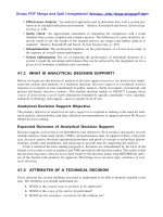
A typical interaction surface is shown in Figure II-2. The column capacity interaction volume is numerically described by a series of discrete points that are generated on the three-dimensional interaction failure surface. The coordinates of these
points are determined by rotating a plane of linear strain in three dimensions on the
section of the column as described in Figure II-1.
The area associated with each rebar is placed at the actual location of the center of
the bar and the algorithm does not assume any simplifications in the manner in
which the area of steel is distributed over the cross section of the column. The interaction algorithm provides corrections to account for the concrete area that is displaced by the reinforcing in the compression zone.
10
Design of Columns
Chapter II Design Algorithms
Axial compression
+P0
Pmax
Pbx
Curve #1
Curve #NRCV
Pby
Curve #2
M by
3
M bx
1
2
My
Mx
-P0
Axial tension
Figure II-2
A Typical Column Interaction Surface
The effects of code specified strength reduction factors and maximum limit on the
axial capacity are incorporated in the interaction surfaces. The formulation is based
consistently upon the general principles of ultimate strength design, and allows for
rectangular, square or circular, doubly symmetric column sections. In addition to
axial compression and biaxial bending, the formulation allows for axial tension and
biaxial bending considerations as shown in Figure II-2.
Design of Columns
11
ETABS Concrete Design Manual
Axial Compression
Lines Defining
Failure Surface
C
L
P
o
Mx
My
MY
MX
Axial Tension
Figure II-3
Geometric Representation of Column Capacity Ratio
The capacity check is based on whether the design load points lie inside the interaction volume in a force space, as shown in Figure II-3. If the point lies inside the volume, the column capacity is adequate, and vice versa. The point in the interaction
volume (P, M x , and M y ) which is represented by point L is placed in the interaction space as shown in Figure II-3. If the point lies within the interaction volume,
the column capacity is adequate; however, if the point lies outside the interaction
volume, the column is overstressed. As a measure of the stress condition of the column, a capacity ratio is calculated. This ratio is achieved by plotting the point L, defined by P, Mx and My, and determining the location of point C. The point C is defined as the point where the line OL (if extended outwards) will intersect the failure
surface. This point is determined by three-dimensional linear interpolation between
the points that define the failure surface. The capacity ratio, CR, is given by the ratio OL OC .
12
Design of Columns
Chapter II Design Algorithms
Figure II-4
Moment Capacity M u at a Given Axial Load Pu
• If OL = OC (or CR=1) the point lies on the interaction surface and the column is
stressed to capacity.
• If OL < OC (or CR<1) the point lies within the interaction volume and the column capacity is adequate.
• If OL > OC (or CR>1) the point lies outside the interaction volume and the column is overstressed.
The capacity ratio is basically a factor that gives an indication of the stress condition of the column with respect to the capacity of the column. In other words, if the
axial force and biaxial moment set for which the column is being checked is amplified by dividing it by the reported capacity ratio, the point defined by the resulting
axial force and biaxial moment set will lie on the failure (or interaction volume) surface.
Design of Columns
13
ETABS Concrete Design Manual
The shear reinforcement design procedure for columns is very similar to that for
beams, except that the effect of the axial force on the concrete shear capacity needs
to be considered.
For certain special seismic cases, the design of column for shear is based on the capacity-shear. The capacity-shear force in a particular direction is calculated from
the moment capacities of the column associated with the factored axial force acting
on the column. For each load combination, the factored axial load is calculated, using the ETABS analysis load cases and the corresponding load combination factors.
Then, the moment capacity of the column in a particular direction under the influence of the axial force is calculated, using the uniaxial interaction diagram in the
corresponding direction as shown in Figure II-4.
Design of Joints
To ensure that the beam-column joint of special moment resisting frames possesses
adequate shear strength, the program performs a rational analysis of the beamcolumn panel zone to determine the shear forces that are generated in the joint. The
program then checks this against design shear strength.
Only joints having a column below the joint are designed. The material properties
of the joint are assumed to be the same as those of the column below the joint.
The joint analysis is done in the major and the minor directions of the column. The
joint design procedure involves the following steps:
h
• Determine the panel zone design shear force, V u
• Determine the effective area of the joint
• Check panel zone shear stress
The following three sections describe in detail the algorithms associated with the
above mentioned steps.
Determine the Panel Zone Shear Force
For a particular column direction, major or minor, the free body stress condition of
a typical beam-column intersection is shown in Figure II-5.
The force V uh is the horizontal panel zone shear force that is to be calculated. The
forces that act on the joint are Pu , V u , M uL and M uR . The forces Pu and V u are axial
force and shear force, respectively, from the column framing into the top of the
joint. The moments M uL and M uR are obtained from the beams framing into the
14
Design of Joints
Chapter II Design Algorithms
joint. The joint shear forceV uh is calculated by resolving the moments into C and T
forces.
Figure II-5
Beam-Column Joint Analysis
The location of C or T forces is determined by the direction of the moment using
basic principles of ultimate strength theory. Noting that TL = C L and TR = C R ,
V uh = TL + TR - V u
Design of Joints
15
ETABS Concrete Design Manual
The moments and the C and T forces from beams that frame into the joint in a direction that is not parallel to the major or minor directions of the column are resolved
along the direction that is being investigated, thereby contributing force components to the analysis.
In the design of special moment resisting concrete frames, the evaluation of the design shear force is based upon the moment capacities (with reinforcing steel
overstrength factor, , and no factors) of the beams framing into the joint,
(ACI 21.5.1.1, UBC 1921.5.1.1). The C and T force are based upon these moment
capacities. The column shear forceV u is calculated from the beam moment capacities as follows:
Vu =
M uL + M uR
H
See Figure II-6. It should be noted that the points of inflection shown on Figure II-6
are taken as midway between actual lateral support points for the columns.
The effects of load reversals, as illustrated in Case 1 and Case 2 of Figure II-5 are
investigated and the design is based upon the maximum of the joint shears obtained
from the two cases.
Determine the Effective Area of Joint
The joint area that resists the shear forces is assumed always to be rectangular in
plan view. The dimensions of the rectangle correspond to the major and minor dimensions of the column below the joint, except if the beam framing into the joint is
very narrow. The effective width of the joint area to be used in the calculation is
limited to the width of the beam plus the depth of the column. The area of the joint is
assumed not to exceed the area of the column below. The joint area for joint shear
along the major and minor directions is calculated separately (ACI R21.5.3).
It should be noted that if the beam frames into the joint eccentrically, the above assumptions may be unconservative and the user should investigate the acceptability
of the particular joint.
Check Panel Zone Shear Stress
The panel zone shear stress is evaluated by dividing the shear forceV uh by the effective area of the joint and comparing it with the following design shear strengths
(ACI 21.5.3, UBC 1921.5.3) :
16
Design of Joints
Chapter II Design Algorithms
ì20 j
v
ï
= í15 j
ï12 j
î
f c¢ , for joints confined on all four sides,
f c¢ , for joints confined on three faces or on two opposite faces,
f c¢ , for all other joints,
where j = 0.85 .
(ACI 9.3.2.3, UBC 1909.3.2.3, 1909.3.4.1)
For joint design, the program reports the joint shear, the joint shear stress, the allowable joint shear stress and a capacity ratio.
POINT OF
INFLECTION
Vu
COLUMN
ABOVE
TOP OF BEAM
COLUMN
HEIGHT
(H)
PANEL
ZONE
L
Mu
TL
CR
Vuh
TR
CL
R
Mu
COLUMN
BELOW
Vu
POINT OF
INFLECTION
ELEVATION
Figure II-6
Column Shear Force, V u
Design of Joints
17
ETABS Concrete Design Manual
Beam/Column Flexural Capacity Ratios
At a particular joint for a particular column direction, major or minor, the program
will calculate the ratio of the sum of the beam moment capacities to the sum of the
column moment capacities, (ACI 21.4.2.2, UBC 1921.4.2.2).
å
Me
³
å5
6
Mg
(ACI 21.4.2.2, UBC 1921.4.2.2)
The capacities are calculated with no reinforcing overstrength factor, , and including factors. The beam capacities are calculated for reversed situations (Cases
1 and 2) as illustrated in Figure II-5 and the maximum summation obtained is used.
The moment capacities of beams that frame into the joint in a direction that is not
parallel to the major or minor direction of the column are resolved along the direction that is being investigated and the resolved components are added to the summation.
The column capacity summation includes the column above and the column below
the joint. For each load combination the axial force, Pu , in each of the columns is
calculated from the ETABS analysis load conditions and the corresponding load
combination factors. For each load combination, the moment capacity of each column under the influence of the corresponding axial load Pu is then determined separately for the major and minor directions of the column, using the uniaxial column
interaction diagram, see Figure II-4. The moment capacities of the two columns are
added to give the capacity summation for the corresponding load combination. The
maximum capacity summations obtained from all of the load combinations is used
for the beam/column capacity ratio.
The beam/column flexural capacity ratios are only reported for Special Moment-Resisting Frames involving seismic design load combinations.
P-D Effects
The ETABS design algorithms require that the analysis results include the P-D effects. The P-D effects are considered differently for “braced” or “nonsway” and
“unbraced” or “sway” components of moments in frames. For the braced moments
in frames, the effect of P-D is limited to “individual member stability”. For unbraced components, “lateral drift effects” should be considered in addition to “individual member stability” effect. In ETABS, it is assumed that “braced” or
“nonsway” moments are contributed from the “dead” or “live” loads. Whereas,
“unbraced” or “sway” moments are contributed from all other types of loads.
18
Beam/Column Flexural Capacity Ratios