MPLS Lab Configuring Frame Mode MPLS
Bạn đang xem bản rút gọn của tài liệu. Xem và tải ngay bản đầy đủ của tài liệu tại đây (273.09 KB, 37 trang )
MPLS Lab
• This lab is mostly copied from a Cisco
Networking Academy CCNP level lab titled
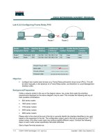
– Lab 4.1 Configuring Frame Mode MPLS
Copyright 2011 Kenneth M. Chipps Ph.D. www.chipps.com
1
MPLS Lab
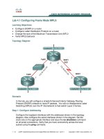
• Here is the topology to create in GNS3
Copyright 2011 Kenneth M. Chipps Ph.D. www.chipps.com
2
MPLS Lab
Copyright 2011 Kenneth M. Chipps Ph.D. www.chipps.com
3
MPLS Lab
• In this lab, you will configure a network
using EIGRP as the routing protocol
• Then run MPLS over the IP internetwork to
fast-switch Layer 2 frames
• Here is the configuration for each router
Copyright 2011 Kenneth M. Chipps Ph.D. www.chipps.com
4
R1
•
•
•
•
•
•
•
•
enable
config t
interface loopback 0
ip address 172.16.1.1 255.255.255.0
interface fastethernet 0/0
ip address 172.16.12.1 255.255.255.0
no shutdown
exit
Copyright 2011 Kenneth M. Chipps Ph.D. www.chipps.com
5
R1
•
•
•
•
•
•
•
router eigrp 1
no auto-summary
network 172.16.0.0
interface fastethernet 0/0
mpls ip
exit
end
Copyright 2011 Kenneth M. Chipps Ph.D. www.chipps.com
6
R2
•
•
•
•
•
•
•
enable
config t
interface loopback 0
ip address 172.16.2.1 255.255.255.0
interface fastethernet 0/0
ip address 172.16.12.2 255.255.255.0
no shutdown
Copyright 2011 Kenneth M. Chipps Ph.D. www.chipps.com
7
R2
•
•
•
•
•
interface serial 1/0
ip address 172.16.23.2 255.255.255.0
clockrate 64000
no shutdown
exit
Copyright 2011 Kenneth M. Chipps Ph.D. www.chipps.com
8
R2
•
•
•
•
•
•
•
router eigrp 1
no auto-summary
network 172.16.0.0
interface fastethernet 0/0
mpls ip
exit
end
Copyright 2011 Kenneth M. Chipps Ph.D. www.chipps.com
9
R3
•
•
•
•
•
•
•
•
enable
config t
interface loopback 0
ip address 172.16.3.1 255.255.255.0
interface serial 1/0
ip address 172.16.23.3 255.255.255.0
no shutdown
exit
Copyright 2011 Kenneth M. Chipps Ph.D. www.chipps.com
10
R3
•
•
•
•
•
•
•
router eigrp 1
no auto-summary
network 172.16.0.0
interface fastethernet 0/0
mpls ip
exit
end
Copyright 2011 Kenneth M. Chipps Ph.D. www.chipps.com
11
Check Connectivity
• When everything is configured, ping from
R1 to R3
– ping 172.16.3.1
• Check the routing table
– show ip route
Copyright 2011 Kenneth M. Chipps Ph.D. www.chipps.com
12
Check Connectivity
Copyright 2011 Kenneth M. Chipps Ph.D. www.chipps.com
13
Check Connectivity
• On R1, if you perform a traceroute to the
R3’s loopback, you see the path the
packet follows
• Observe this
• This output changes slightly once we
configure MPLS
Copyright 2011 Kenneth M. Chipps Ph.D. www.chipps.com
14
Check Connectivity
Copyright 2011 Kenneth M. Chipps Ph.D. www.chipps.com
15
MPLS Configuration
• As discussed earlier MPLS is a
standardized protocol that allows routers
to switch packets based on labels, rather
than route switch packets based on
standards in the protocol’s routing formula
Copyright 2011 Kenneth M. Chipps Ph.D. www.chipps.com
16
MPLS Configuration
• Under normal IP routing, every
intermediate system looks up the
destination prefix of an IP packet in the
Routing Information Base of a router or in
the Forwarding Information Base of a fast
switch at every Layer 3 node
Copyright 2011 Kenneth M. Chipps Ph.D. www.chipps.com
17
MPLS Configuration
• Instead of switching that is based on
prefix, the first router running MPLS can
encapsulate the IP packet in an MPLS
frame and then further encapsulate the
packet in the Layer 2 frame before
sending it across one of many supported
Layer 2 media
Copyright 2011 Kenneth M. Chipps Ph.D. www.chipps.com
18
MPLS Configuration
• At the next MPLS-enabled LSR - Label
Switch Router, the MPLS frame is read
and the IP packet is switched as an MPLS
frame from router to router with little
rewrite at each node
Copyright 2011 Kenneth M. Chipps Ph.D. www.chipps.com
19
MPLS Configuration
• This allows routers to switch multiple
protocols - hence the name - using the
same switching mechanism, as well as
perform some other functionality not
available in traditional destination-based
forwarding, including Layer 2 VPNs - ATM,
Layer 3 VPNs, and traffic engineering
Copyright 2011 Kenneth M. Chipps Ph.D. www.chipps.com
20
MPLS Configuration
• Configuring the interface-level command
mpls ip on an interface tells the router to
switch MPLS packets inbound and
outbound on that interface as well as
attempt to bring up MPLS adjacencies with
the LDP - Label Distribution Protocol out
that egress interface
Copyright 2011 Kenneth M. Chipps Ph.D. www.chipps.com
21
MPLS Configuration
• LDP facilitates communication between
MPLS peers by allowing them to inform
each other of labels to assign packets to
particular destinations based on Layer 2,
Layer 3, or other significant information
Copyright 2011 Kenneth M. Chipps Ph.D. www.chipps.com
22
Verify MPLS Configuration
• MPLS has many show commands that you
can use to verify proper MPLS operation
• Issue the
– show mpls interfaces
• command to see a quick summary of
interfaces configured with MPLS
• Keep in mind that you will see this output
because you applied the mpls ip command
to these interfaces
23
Copyright 2011 Kenneth M. Chipps Ph.D. www.chipps.com
Verify MPLS Configuration
Copyright 2011 Kenneth M. Chipps Ph.D. www.chipps.com
24
Verify MPLS Configuration
• Issue the
– show mpls ldp discovery
• command to find out local sources for LDP
exchanges and the show mpls ldp
neighbor command to show LDP
adjacencies
• Notice that MPLS chooses its IDs based
on loopback interfaces, similar to other
protocols such as OSPF and BGP
Copyright 2011 Kenneth M. Chipps Ph.D. www.chipps.com
25