1235X 08
Bạn đang xem bản rút gọn của tài liệu. Xem và tải ngay bản đầy đủ của tài liệu tại đây (2.03 MB, 28 trang )
8
Wire and Coil Coatings
Magnet wire is used principally in the electrical and electronics industries for coils,
inductors, transformers, armatures, solenoids, and other windings. Wire may be
insulated and protected with a wide variety of coating materials which may be
classified according to the manner of application. Wires may be dipped in a liquid
bath of the resin solution, or coated by extrusion of solid thermoplastic resins.'
Extruded insulation, such as polyvinyl chloride, polyethylene, or polytetrafluoroethylene, is relatively thick in relation to the wire diameter and is therefore used chiefly for interconnect and lead wires. Dip coatings may be applied in
very thin layers and consequently are employed for the insulation of thin magnet
wire and for the impregnation of coils and windings. This chapter covers only the
liquid-resin coatings such as the varnishes, enamels, and impregnating coatings.
For purposes of comparison, however, some properties of the extruded types will
also be given.
MAGNET-WIRE CLASSIFICATIONS
Magnet wire may be classified as coated wire, coated wire with fibrous wrappings,
and wire with impregnated fibrous wrapping. In the third type the fibrous wrapping
may be cotton, polyester, or glass impregnated with resin.ous materials. Wire
coated with only an organic coating is frequently referred to as enameled wire or
simply coated wire: the organic coating is applied directly to the conductor and is
the only dielectric material used.
Magnet wire may also be classified according to National Electrical Manufacturers Association (NEMA) thermal ratings (Table 8-1). In order to qualify for an
NEMA thermal classification, a wire must meet two criteria: its extrapolated life
must be 20,000 hr or more at or above the thermal class rating, and the tested life
250
Wire and Coil Coatings
Table 8-1: Magnet-Wire Classifications'
Type of insulation
H E M desiqnatior
Class, C
nu I -c
105
iiw2-c
105
Nyi on-coated, romd
nib-c
105
Foiyvinyl, iorsii-coated, round
nw-c
105
nwI8-c
105
nw-c
105
nuxi-c
130
Pal yester -coated , round
nws-c
155
Pol yester -nyl on-coated, round
"24-C
155
Polyester-iride or polyester-arideimi de-coated , round
nwi2-C
190
Rodified p i r e s t e r or po1ye:krimide or polyester-a;aide-imide
0ver:oated with polyamide-imide,
HWi5-C
200
riodified polyester or polyester1 m i de or pol yeiter-amide-iai de
overcoated uitn polyaride-inide,
rectangular
tMb-C
205
Aromatic polyimide-coated, round
tlkil6-C
220
nw2o-c
220
tlY45-c
155
nii46-c
155
, round
nwt7-c
180
,
nu48-c
180
none
220
O!eoresinour-enane!-~oaied, iound
Fo! ycrethane-coated
, round
Polyvinyl, ioraai-coated
, r e c t a g u l ar
Polyvinyl , form!-nylon-coated,
seltbonding, round
Folyurethane-nylon-coated
, round
r 3UEG
Arorati c pol yinide-coated
, rectangulai
, round
Pol rester -91 ass-f i ber-covered
Pol yest~r-gla55-f i ber-covered,
rectanqul ar
Polyester -glass-f iber -covered
Pol yester-glass-ii ber-covered
rec t anqul ar
Pol yester -glass-i i her-covered,
rectangular
251
252 Handbook of Polymer Coatings for Electronics
of the specimen must not be less than 5,000 hr at 20°C above the thermal class
rating. Another specification, Federal Specification J-W-1177, defines the same
thermal classes as the NEMA, but the type designations are different.2 Performance requirements for each of these classes and types, including elongation,
solvent resistance, and abrasion resistance, are given in J-W-1177.
Finally, magnet wire may be classified according to the thickness of the coating.
Enameled wire is furnished in various coating thicknesses as Single, Heavy, Triple,
etc., again according to NEMA standards.3 Classificationsfor wire coated with thin
polyvinyl formal may be found in Tables 8-2 and 8-3.
WIRE-COATING TYPES
Most of the coating types discussed in Chapters 1 to 3 may be used as wire
coatings and as coil-impregnating resins. Although they are formulated differently,
the basic properties of each type are essentially the same. Accordingly, silicones,
polyimides, and fluorocarbons are best suited for very-high-temperatureapplications, polyurethanes for ease of removal, and epoxies for solvent and chemical
resistance. Several additional polymer types are also used for wire coatings.
Among these are the oleoresinous varnishes and the polyolefins (polyethylenes,
polypropylenes, and irradiated polyolefins).
In general, wire and impregnation coatings consist of high molecular weight
polymers, either of the thermoplastic (linear) or thermosetting (cross-linked)types.
The thermoplastics have definite softening or melting points, above which the
Table 8-2: Dimensions of AWG Wire Sizes 31 to 44
Bare-wire diameter, in.
Min.
increase
in dium.,
in.
AWC,
size
Sir e
Y
hlas.
ovrrall
hlin.
Nominal
31
32
33
35
35
0.0088
0.00i9
0.0070
0.0062
0.0055
0.0089
0.0080
0.0071
0.0063
0.0056
0.0090
0.0081
0.0072
0.0064
0.0057
0.0006
0.0006
0.000s
0.0005
0.0005
0.0065
36
3i
38
39
0.0049
0.0050
0.0044
0.0045
0.00.1u
0.0051
0.0046
O.ooo5
0.0003
0.0003
0.0002
0.0002
0.0058
0.0052
0.0047
0.0041
0.0037
0.0002
0.0002
0.0002
0.0033
0.0030
0.0026
0.0024
40
41
42
43
44
0.0039
0.0035
0.0030
0.0027
0.0024
0.0021
0.0019
0.0041
0.0035
0.0031
0.0036
0.0032
0.0028
0.0023
0.0022
0.0020
0.0029
0.0026
0.00'3
0.0021
0.o001
diam.,
in.
0.0100
0.0091
0.0081
0.0072
Min.
increase
in diam.,
in.
overall
diam..
in.
0.0013
0.0012
0.0011
0.0010
O.OOO9
0.0108
0.0098
0.0088
0.0078
0.0070
0.0008
0.0008
O.ooO7
0.0063
0.0057
0.0051
O.OOO6
O.OOO6
6 . m
O.ooO5
O.OOO4
0.0004
0.0004
Max.
O.OCkI.5
0.0036
0.0032
0.0029
0.0027
Wire and Coil Coatings 253
Table 83: Characteristics of AWG Wire Sizes 45 to 56
AWC
size
-
Theoretical*
nominal
hare-wire
diameter.
in.
Chductor resistancr at 20°C.
ohms/ftf
Min.
Nominal
%lax.
__
Min.
increase in
diani..
in.
%la\.
overall
diam.,
in.
Min.
increaw in
diani..
in.
otrrall
diam.,
in.
Max.
45
0.00176
3.080
3.348
3.616
o.Ooo10
0.00205
0.00030
0.00230
46
0.00157
0.00140
0.00124
0.00111
O.OOO99
3.870
4.868
6.205
7.i44
9.734
4.207
5.291
6.745
8.417
10.58
4.544
5.714
7.285
9.090
11.43
0.00010
o.Ooo10
0.00010
o.oO01o
0.00185
0.00170
0.00150
0.00130
0.00120
0.00030
0.00030
0.00020
0.00020
0.00020
0.00210
0.00190
0.00170
0.00150
0.00140
13.39
17.05
21.17
26.98
34.28
14.46
18.41
22.86
29.14
37.02
47
48
49
50
51
52
53
54
55
56
-
O.OOO88
0.00078
0.00070
O.OOO62
O.ooO.55
0.00049
12.32
15.69
19.48
24.82
31.54
o.oO01o
43.19
-39.73
46.64
Theoretical nominal bare-wire diameters are in accordance with the Copper Wire Tables, .Vat/. Bur. Srds. Handbook
100.
t Conductor diameter tolerances are s h o w as resistance values and shall hr determined by measuring the resistance of
the wire in accordance with the USA Standard “Method of Test for Resistivit) of Electrical Conductor Materials,”
C7.24-1%1, where applicable. A specimen at least 5 ft long shall h used.
materials are not usable, especially where local stresses are to be applied. Examples of thermoplastic coatings include Teflons and nylons. The thermosetting
coatings are more resistant to “cut through” and have improved solvent resistance.
Examples include silicones, polyesters, and polyvinyl formals. Some wire-coating
types, trade names, and manufacturers are given in Table 8-4, and a summary of
advantages and limitations of wire coatings is given in Table 8-5.
As indicated in Table 8-1, many wire coatings consist of a combination of two, or
even three, different polymers. In this way characteristics are achieved which could
not be obtained with any one polymer alone. Thus polyvinyl formal may be coated
with nylon to provide the lubricating properties of nylon for greater ease in winding.
Polyvinyl formal is also frequently overcoated with polyvinyl butyral to render the
coating self-bonding either by heat or solvent action. This property is especially
important in the fabrication of formed coils.
Plain-enamel or Oleoresinous Coatings
The terms “plain enamel” or “oleoresinous varnish” refer to the natural resinous
coatings that have been used as standard wire insulation for more than 60 years.
They are derived from natural drying oils such as linseed oil or tung oil and are
cure4 through the air oxidation of double bonds. The coatings may be augmented
by “cooking in” fossil or synthetic resins to improve their hardness and resistance
to solvents. Because of the dark color of the finish wire, such coatings are sometimes referred to as “black enamels.” Oleoresinous coatings are rapidly being
replaced by the higher-performance synthetic coatings.
254
Handbook o f Polymer Coatings for Electronics
Table 8-4: Wire Coating Types4
Wanuf acture
Trade nare
Chemical type
leiperature
rating, C
Applications
~~
Ananag
bnac1ad-A (Hnc-ai
Polyester/polyiride-aride
Nylac (SNLI
Pol yurethanelpol y a i i de
Forrvar IHF)
Polyvinyl forral
20OICu1/220(AI
,
H e r i e t i c r e f r igerat i on
penerators, i n t e g r a l
r o t o r s , b a l l a s t transforrers, i i c r o w w
rotors.
130 t o 155
E l e c t r o n i c coils, r o t o r
coils, l i g h t i n g
transf oriers.
105
Oi I - f 1 1 l e d t r a n s f o r m s ,
pole i o u n t and pad
mount h i p h voltage
c i r c u i t breakers.
Anatherr (HAT-NCI
Polyesterlpolyaride
180
Fractional and subfract i o n a l open rotors,
portable generators,
telephone equipient.
A r o i a t i c polyester
220
Herret ic r e f r igerat i on
r o t o r s , sealed relays,
encapsulated nindings,
dry-type, o i l - f i l l e d
transformers, large hp
rotors.
130 t o 200
Transformers.solenoids,
coils, motors, ballasts
Arcor
Hot-nelt (Nyleze)
Nylon over polyurethane
BeldenlEYP
Celenarel
C e l l ul ose acetst e
130
Trnmformerr, ignition
coils, relays
Celeiid
Polyester
180
Transformer coils, automotive coils, relays.
Beldtherr 200
Cross-linked, i o d i f i e d
polyester
200
Coils, relays; constant
terperature o f 200 C;
low outgassing.
Belden llt
Polyiiide
220
C o i l s , relays, transf orrers.
transforiers.
Bridgeport
Po1yuret hane
Polyurethane
I55
S r a l l i o t o r s , relays,
transforrers.
:orwar
Polyvinyl formal
IO5
Small r o t o r s , relays,
'01 y-Bond
Polyurethane r i t h p o l y v i n y l
butanol topcoat
105
Srall r o t o r s , relays,
Polyurethane w i t h nylon
topcoat
130
'01 y-Ny 1on
transforiers.
5ralI rotors, relays,
trmsforiers.
(continued)
Wire and Coil Coatings
255
Table 8-4: (continued)
I
-
Cheii t a l type
Terperature
rating, C
Terasod
Solderable polyester
I55
S r a l l rotors, relays,
transforiers.
lsonel 200
nodi f i e d polyester
180
SrdI i n t o r s , relays,
transforrers.
Hod i f ied pol yest e r - i r i d e
1eo
Srall rotors, relays,
Hanufacture
Trade naie
Applications
transforrers.
Canada # i r e
isser Group
Polyvinyl f o r r a l
Polythane
(Yestinghouse)
Polyvinyl f o r r a l
105
O i I-f i 1 I ed transforrers.
Forrel Epoxy
Sel (-bonding pol yvinyl
forral
105
O i 1 - f i l l e d transf orrers.
Pol yurethane-nylon
I30
P u t o i o t i v e generators and
alternators, ballasts,
open i o t o r s .
qagnesol
Solder able r o d i f i e d
polyester
155
Rutoiotive generators and
alternators, ballasts,
open rotors.
t r i o r e d Maqneteip
Hodified polyester overcoated w i t h polyarideiride
200
Mercury ballasts, rotors,
dry-type transforrers,
coils, h e r r e t i c iotors.
IL
llroiatic polyiride
220
Dry-type and d i s t r i b u t i o n
transforrers, heavy duty
i o t o r s , t r a c t i o n i o tors.
:apton
Kapton
220
Traction i o t o r s , c o i l s
under strong shock.
'heraetex GP-200
Polyesterlpol y a i i d e - i r i d e
200
hotors, dry-type
transforrers, large coil
applications.
Iller
Aroiatic polyiride
220
Fhp'and i n t e g r a l hp"
rotor!,;
high terperature
continuous duty c o i l s
and relays; h e r r e t i c and
sealed units; heavy duty
hand t o o l r o t o r s ,
encapsulated coils.
Iytherr
Polyesterlpol yaride
180
Fhp and i n t e g r a l hp
rotors; retays and
c o i l s ; c o n t r o l and drytype transforiers;
encapwlated c o i l s ; d-c
f i e l d coils.
(continued)
256 Handbook of Polymer Coatings for Electronics
Table 8-4: (continued)
Manuf acturei
Trade n a i e
Chemical type
Tenperature
rating, C
Appl i c a t i o n s
tIRi6P200
Polyesterlpol y a i i d e - i i i d e
200
Fhp and i n t e g r a l hp
rotors; dry-type
transforiers; a u t o i o t i v e
and e l e c t r i c tool
ariatures.
Solider
nodified polyester-iiide
I BO
Special transf o r i e r coi 1 s,
shaded p o l e i o t o r coils,
a u t o i o t i v e c o i Is,
electronic coils.
Soderex
Polyurethane
1so
Snail i o t o r s , relays, bell
ringer coils,
encapsul ated c o i Is.
Noaex
Polyaiide tape
200/220
Dry-type or o i l - f i l l e d
transforiers, l i f t i n p
iagnets, fori-uound
co115.
i i e t t r i sol a
Polys01 140
Nodified polyurethane
140
molded and encapsulated
coils; autoaotive c o i l s ;
audio RF, instrument,
and sia11 poner
t r a n s f o r i e r s ; sia11
r o t o r s , arnatures.
Polysol-N
Pol yurethane-nylon
140
holded and encapsulated
c o i l s ; automotive c o i l s ;
audio RF, instrument,
and siall power
transforiers; toroidal
coils.
Ester-N
Pol y i a i de-aiide-ester
I55
Specialty poner
transforiers;
subfract ional rotors;
control coils;
aut o i o t i ve c o i 1s.
Estersol I80
Pol yinide-aride-ester
180
Specialty poner
transf orners;
subfractional i o t o r s ;
control coils;
a u t o i o t i v e c o i 1s.
Amidester 200
Polyiiide-aiide-ester
200
Hermetic rotors; d-c
i o t o r s ; dry-type transforiers; control transformers; e l e c t r o n i c
coils.
(continued)
Wire and Coil Coatings
257
Table 8-4: (continued)
Terperature
rating, C
Hanuf acture
Trade name
Phelps Godg
A.P. Eondeze (AP-8)
Therrosetting Polyester
w i t h l i n e a r aride-imide
overcoat, self-bonding
topcoat
Armored PolyThermaleze 2000
(APT21
Therrosett ing Polyester
with linear w i d e - i r i d e
overcoat, self-bonding
topcoat
Bondeze-T IBDZ-TI
Tinnable polyester w i t h
self-bonding topcoat
150
Fhp rotors; solenoids;
c l u t c h and brake c o i l s .
Foriareze (FI
Polyvinyl f o r r a l
105
O i l - f i l l e d transforrers.
liidete
Arorat i c pol y i i i d e
220
Dry-type transforrers,
t r a c t i o n rotors, d-c
f i e l d c o i l s , subrersible
purp rotors.
lllR Therraleze
Therrosetting polyester
n i t h rodified ararid
overcoat
200
ilotors used i n high
i o i s t u r e and h e r r e t i c
application.
Nyle:e (YYLZ)
Polyurethane w i t h nylon
(polyaoidel overcoat
130
Coils, universal rotors.
Sy-Bondeze (5-V-8)
Polyurethane with nylon
105
Voice c o i l s , encapsulated
sol enol ds, t o y r o t ors.
Sodereze ISGZI
Polyurethane
1051155
I g n i t i o n c o i l s , low
vol t age transf orrers,
relays, solenoids.
Formvar
Polyvinyl f o r i r l
105
011-f i I1 ed d i str i but i on
(n/R T I )
Rea
Cherical type
I30
zoo(cul /220(A
Applications
Vole c o i l s ; c l u t c h and
brake coils; bobbinless
501enoi ds.
Gry-type transforrers;
h e r r e t i c rotors; t o o l
notors; t e l e v i s i o n f l y back transforrers; t o r o i d a l TV yokes; autorot i v e a l t e r n a t o r stators;
501enol ds.
t r a n s f oroers.
Solvar
Hodified polyurethane
I05
COi15.
Nysol
nodi f i e d pol yurethane
with nylon overcoat
I30
c0115,
Hy-Silk Arnid-
Modified polyester with
p r o p r i e t a r y overcoat
ias
not ors.
Thersol
nodif ied, solderable polyester
180
COi15, rotors.
THEHN-ID
i l o d i f i e d polyester
200
Coils.
Therm
(continued)
258
Handbook of Polymer Coatings for Electronics
Table 8-4: (continued)
Uanufacturei
Nest i nqhousi
Trade
I
Cheiical type
#Ills?
Teiperature
rating, C
Applications
THERll-AI I D
llodified polyester with
polyaiide-iiide overcoat
200
Herietic motors.
Super Hy-Silk 200
llodi f i ed polyester wi t h
polyaride-iiide overcoat
rith proprietary lubricant
200
Uotors.
POlythdne
llodified polyurethane
105
Siall coils.
Nythane
Uodified polyurethane with
polyaiide overcoat
150
Coils.
Unega-Klad
Hodif ied polyester with
aiide-iiide overcoat
209
Tr snsf ormer s, eo tors.
ttydroihield
nodi f i ed polyester Mit h
aride-hide overcoat
200
Transfwiers, motors.
Oieqa-Stir
Bondable iodified polyester
with amide-iiide overcoat
200
Coils.
ATOUL
Ilroiatic polyimide
220
llotw mrnufrcturinq and
repair.
*Fractional horsepower.
**Horsepower.
Table 8-5: Summary of Properties of Various Coated Wires
Thermal
rating, "C
Coating
. . .. . . ..
105
. . .. . . . . . . .
105
. . . .. .
105
..
105
Polyvinyl formal
Polyurethane
Polyaniidc (nylon).
Polyvinyl formal, nvlon.
Advantages
Toughness. dielectric
strength; compatible with
other coatings; hat-shoch
resistant.
Dielectric strength, chemical
resistance, moisture and
corona resistance; c o m
patible with solvents and
chemicals; solderable
without stripping.
Toughness, dielectric
strength, solvent resist.
a w e ; solderable; good
\$iiidability.
Toughness, solvent resistance; good windability;
heat-shock rL.sistmt.
Limitations.
Crazes in polar solvents.
Low thermal resistance.
High moisture absorption;
high electrical loss at all
frequencies.
Nylon portion subject to
same limitations as
nylon.
(continued)
Wire and Coil Coatings
259
Table 8-5: (continued)
Thermal
rating, "C
Coating
Polyvinyl formal, polyvinyl.
butyral , . . . . . . . . . . . .
105
Polyurethane, nylon
105
Polyester . . . . . . . .
155
Poly tetra Huoroethylene
(Teflon) . . . . . . . . . .
200
Poly imide
. . . .. ..
m
Advantages
Limitations*
Boodability, dielectric
strength; heat-shock resistant.
Solvent resistance;
solderable.
Toughness, dielectric
strength, chemical resistance, cut-through
resistance
Vibration; high mechanical
stress.
Thermal stability, chemical
stability, dielectric
strength; low dielectric
constant.
High overload resistance,
thermal resistance.
chemical stahility,
radiation resistance;
high cut-through
resistance.
High abrasion; high gas
permeability; cold flow;
poor adhesion.
High moisture absorption;
high-frequency losses.
Hydrolyzes in moist sealed
atmosphere.
Stripping difficulty; crazes
in some solvents.
A prebnke at 125°C for 2 to 4 hr after winding relieves film stresses so that crazing does not occur
during subsequent varnish or resin encapsulation.
Polyvinyl Formal and Modified-Polyvinyl Formal Coatings
Coatings based on polyvinyl formal (Formvar), first introduced in 1938 as magnetwire insulation, are still widely used magnet-wire coatings. The base polymer is
synthesized by partially hydrolyzing polyvinyl acetate and then reacting the free
hydroxyl groups of the resulting product with formaldehyde to form the six-membered formal structure. The polymer will therefore contain three basic functional
units-vinyl formal, vinyl alcohol, and vinyl acetate, as follows:
CH2
Vinyl formal
I
I
I
I
I
I
I
I
II
I
I
Vinyl alcohol I
I
I
group
c=o
CH3
Vinyl acetate
group
Molecular Structure of Polyvinyl Formal Resin
260 Handbook of Polymer Coatings for Electronics
Polyvinyl formal used alone has only marginal solvent resistance, hardness, and
other properties. Its properties are greatly improved by modifying the basic resin
through reaction with phenol formaldehyde or cresol formaldehyde resins. Both
resins condense with the free hydroxyl groups of the polyvinyl formal to produce
coatings which are extremely tough and flexible and which possess good abrasion
and solvent resistance. Polyvinyl formal can also be modified with resins such as
melamine, urea, epoxy, and urethanes5
The modifications with urethane are especially favored because of their solderthrough properties. Dip-tinning or soldering at high temperatures (up to 350°C)
may easily be performed without stripping the insulation. Three-component coatings consisting of polyvinyl formal, polyurethane, and polyester are also easy to
solder through and, in addition, have good flow, flexibility, and heat-shock properties, as well as good resistanceto abrasion and solvents.6 In fact, practically all the
solderable magnet-wire coatings on the market are urethane modifications.
Polyurethane Coatings
Polyurethanes used as wire enamels are generally the reaction products of hydroxylated polyesters or hydroxylated polyethers with tolylene diisocyanate. Admixing
these components, however, results in very rapid polymerization-too rapid for any
practical application. For this reason, polyesters containing excess isocyanate
groups are prereacted with phenol to yield adducts which are relatively stable at
room temperature. After application to the wire and subsequent high-temperature
baking, the phenol portion of the adduct is released. In this manner the free
isocyanategroups which are formed can react with hydroxyl groups of the polyester
to form the desired polyurethane coating. This type of polyurethane is the ASTM
Type 3 described in Chapter 1. Other polyurethane wire enamels consist of
reaction products of isocyanates with formvar and, as already mentioned, offer
good solderability. In fact, the largest share of the solderable insulation market
utilizes polyurethane systems.7
Polyester Varnishes and Enamels
Polyester varnishes are produced by the condensation of terephthalic acid, a
glycol, and a polyol such as glycerine. When the proper proportions are mixed and
heated, partial polymerization occurs, leaving the product soluble in solvents. The
general structure for the polyester polymer is
Polyester coatings may be applied to wire by either an automated or a'manual
dipping operation and then baked at 150 to 205°C.They may be used alone or in
conjunction with other compatible wire enamels such as nylons, formvars, polyimides, and polyurethanes. Polyester wire coatings are especially noted for their
excellent thermal properties, which derive from the stability of the ester linkages,
Wire and Coil Coatings
261
high cross-linking density, and the symmetry of the para-substituted benzene
rings. They qualify for Class A (105°C) through Class 200 (200°C) applications.
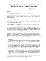
Thermal endurances, measured according to ASTM D 2307, for typical polyester
and polyester-polyimide wire are given in Figure 8-1. Polyester varnishes also
provide good chemical and solvent resistance, except to strong alkalis and mineral
acids. Both alkalis and acids react slowly at room temperature or more rapidly at
elevated temperature, resulting in hydrolysis of the ester linkages and cleavage of
the polymer chain at these sites (Table 8-6).
Polyimide Coatings
Polyimide varnishes and enamels consist of polyamic acid resins dissolved in
highly polar solvents such as dimethylformamide. After evaporation of the solvents,
the coatings are cured by high-temperature baking, which effects ring closures
through the elimination of water. The chemistry and properties of polyimides were
discussed in Chapter 3.
Polyimide coatings excel in high-temperature and radiation resistance. They
belong to Class 220 thermal insulation, i.e., they are capable of withstanding at
least 20,000 hr at 220"C, according to IEEE No. 57 test procedures. Electrical
properties, such as dielectric strength and insulation resistance, are not impaired
even at temperatures of 240°C. The exceptional thermal stability of polyimide
Temperature, "C
Figure 8-1: Thermal endurance of polyester-polyimide varnished wire (ASTM
D 2307, 1,000-volt proof test). (Schenectady Chemicals, Inc.)
262 Handbook of Polymer Coatings for Electronics
Table 8 6 : Effects of Chemicals and Solvents on Isonel51 Polyester Varnish
~
Chemical
1
Control, varnished sample . . . .
Transformer oils . . . . . . . . . . . .
Acetone . . . . . . . . . . . . . . . . . .
Xylol . . . . . . . . . . . . . . . . . . . .
5 percent sulfuric acid . . . . . . .
2 percent sodium hydroxide.
Exposure
Observed effect
None
48 hr at 100°C
24 hr at 25°C
24 hr at 25°C
24 hr at 25°C
2 4 hr at 25°C
llnaffected
Slight softening
Unaffected
Slight attack
Slight swelling
...
Dielectric
strength,
volts/mil
3,150
2,920
3,080
2,980
2,690
2,980
By permission of Schenectady Chemicals, Inc.
varnishes permits the manufacture of smaller motors, transformers, and generators. Because of their low weight loss at elevated temperatures and their high
chemical resistance, polyimide varnishes are useful in encapsulated windings and
hermetically sealed components. Polyimide wire coatings are also compatible with
numerous phenolic, polyester, and epoxy varnishes and encapsulants and are
resistant to most solvents and chemicals. Disadvantages include its hydrolytic
instability at temperatures above 105°C in a sealed system containing moisture
and the difficulty in stripping it off wire. There are very few good methods of
removing polyimide from wire.
IMPREGNATING VARNISHES
After coils and their cores are assembled, the electrical part (for example, a
transformer or toroidal coil) is impregnated with varnish and encapsulated or
otherwise embedded in one of a wide variety of materials (see Figure 8-2).
Complete impregnation serves four main functions: it insulates the wires, allows
better dissipation of heat during operation, provides protection against moisture
and contaminants, and provides better shock and vibration resistance. The exclusion of air and oxygen by thorough impregnation&with organic coatings results in
substantial improvements in thermal life. Epoxy impregnation, for example, may
convert a Class A insulation to a Class B. The cooler operation of coils and
transformers has also permitted a degree of miniaturizationnever before possible.6
Transformers for household electronic equipment, which are not subject to severe
environments, may be coated with low-cost solvent varnishes, treated with asphalt,
or encapsulated with potting resin. Transformers subject to severe environmental
conditions, as in military or aerospace equipment, may be coated with highperformance synthetic polymers (Figure 8-3), potted in plastic cups, molded or cast
in plastic resins designed to meet the more severe conditions.
Wire and Coil Coatings
263
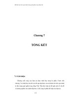
Figure 8-2: Silicone-coatedtoroidal coil. (Dow Corning Corp.)
Figure 8-3: Insulated transformers: (left) silicone-coated; (right) Westinghouse
Fosterite, polyester-coated. (Westinghouse Electric Corporation)
264
Handbook of Polymer Coatings for Electronics
APPLICATION AND WINDING METHODS
Wire coatings are normally applied from solvent solutions. The wire is passed
through a varnish tank, then through a stripper die for build regulation, and finally
through an oven or heating tower to effect solvent removal and cure. Most wire
coatings are applied in multiple thin coats, because single coats invariably contain
pinholes or other breaks in dielectric continuity. Each succeeding coat reduces the
probability of pinholes.
After the coating is applied and cured, the wire is wound into coils for various
electrical uses. The ease with which wire may be wound is a direct function of the
lubricating properties of the coating. Coatings, such as nylons and Teflons, which
have low coefficients of friction possess inherent lubrication. These coatings are
preferred for automated high-speed winding operations. In other cases lubricating
oils may be applied to the wire insulation to facilitate winding, but it is reported that
these oils outgas and contaminate adjacent surfaces. Proprietary surface treatments have been introduced which are capable of reducing the coefficients of
friction by 20 to 90 percent over those of untreated surfaces. One process,
developed by Essex Group, entails grafting polymers to the surface of the wire
coating. The coefficient of friction for nylon-coated insulation is 0.17 but for other
commonly used coatings it may be as high as 0.27.
The reliability of magnet-wire coatings depends not only on their inherent material properties and method of application, but also on the winding process used.
The winding method must be carefully chosen to avoid stresses and mechanical
damage to the wire and insulation and to allow for close packing. Coil winding may
take any one of several forms, depending on the design of the part. The most
common form is one in which the wire is wound in layers, one wire thick, with each
turn adjacent to the next. This type of coil is generally wound on a rectangular or
square coil form, which may be plastic, ceramic, or, in the case of commercial
equipment, even paper. The wire enamel normally provides sufficient insulation for
resisting turn-to-turn electrical stress, but fsr added reliability paper or other insulating materials are frequently used between layers, where the electrical stress is
higher.
In another winding process the coil is wound on molded plastic bobbins, and as
with coils wound on coil forms, sheet material may be inserted between layers. The
finished coil may also be covered by a coil wrapper of sheet material, such as
paper, held in place by pressure-sensitivetape.
In a third type of winding, referred to as precision winding, the wire is passed
over an adhesive applicator and then wrapped on a precisely grooved arbor. Each
turn of wire rests in the groove between turns in the layer below. Since each layer
has a relationshipto the layer beneath of a left-hand thread to a right-hand thread,
a crossover occurs with each turn; the arbors are so designed that all the
crossovers are on one of the four sides of the coil. With fast-drying coatings, the
coil is removed by collapsing the arbor on which it is wound. Precision-wound coils
have the advantage of possessing very high wire density.
A fourth type of winding is necessary where the transformer or inductor core is
toroidal. Intricate winding machines thread the wire through the toroid, forming the
coils directly over the core. Other coils are assembled by inserting the core through
the coil form or bobbin and completing the magnetic circuit by cementing the
pieces of the core or interleaving the individual magnetic-iron punchings.
Wire and Coil Coatings
265
TESTING WIRE COATINGS
Coated wire is most often tested according to procedures described in NEMA MW
1000 or, in the case of military contracts, J-W-1177. Many of the tests in these two
standards are identical. Some of the more commonly used tests are described in
the following discussion.
Film Thickness
Film thickness is determined by measuring the total diameter of the coated wire
with a micrometer, removing the coating in a manner that is not destructive to the
wire, and then measuring the diameter of the bare wire. The difference between
these diameters, divided by 2, gives the thickness of the coating. One method of
removing the coating from copper wire is to burn it off by heating the wire and then
quickly immersing the hot wire in ethyl alcohol. The alcohol dip minimizes the
formation of copper oxide.
Adhesion
Adhesion is measured by elongating a 1O-in. length of wire at 12 in./min. for Size 13
AWG (American Wire Gauge) and larger or by rapidly pulling wire Sizes 14 and
finer. Examination of the wire for separation or cracking at specified magnification
for different wire sizes determines failure.
Flexibility
Flexibility is determined by winding the wire around a mandrel of specified size and
then examining it at a magnification dependent on the size of the wire. Flexibility is
frequently expressed as 1 x , 2 x , 3 x , etc., signifying that the particular wire
coating will withstand winding around a mandrel 1, 2, or 3 times the AWG size of
the wire. Adhesion and flexibility tests are frequently followed by elongation and by
a mandrel-wind test.
Heat Shock
Heat shock is determined by elongating or stretching the wire, winding it around a
mandrel of a size dependent on the wire size, and exposing it to oven heat. The
specimen is then examined under magnificationfor cracking or separation from the
metal.
Elongation
Elongation is measured by stretching a 1O-inch piece of wire at a rate of 12 inches
per minute until the wire breaks. The results are reported as a percentage.
Scrape Resistance
Scrape resistance is measured by either repeated scrape or unidirectionalscrape.
In the repeated-scrape test a machine rubs a 0.016-in.-diameter needle or wire
parallel to the axis of the wire under test, with provisionfor a specified load at a rate
of 60 strokes/min. Each stroke consists of a 360" rotation of an eccentric drive. The
machine is equipped with an electrical circuit which stops the action and a counter
which records the number of strokes at the time of breakthrough of the coating.
266
Handbook of Polymer Coatings for Electronics
The unidirectional-scrape-resistance test, as the name implies, consists of a
scraping action in one direction only. The machine rubs a 0.009-in.-diameter
needle on the coated wire at 16-in./min at right angles to the wire, with a constantly
increasing load. The machine is equipped with an electrical circuit for detecting the
time to failure. Failure is recorded as "grams to fail."
Springback
Springback is a measure of the ability of the wire to unwind. A wire sample is
wound three turns around a mandrel of a size dependent on the wire size at a rate
of 5 to 10 rpm. After winding, one end of the coil is clamped and the other end
allowed to unwind. The softer the wire the less the tendency to spring back. This
test is used for wire sizes 14 to 30 AWG inclusive.
Thermoplastic Flow
Thermoplastic flow, also referred to as cut-through, is the temperature at which the
coating softens and flows under defined conditions of pressure. According to the
NEMA test procedure, two pieces of 18 AWG insulated wire are placed at right
angles to each other and pressed by a load of 2,000 g. or 36 AWG wire is used with
a 1000 g load. The wire conductors, pressed against a steel plate, are connected to
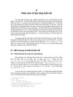
a 110-volt ac power supply with an indicating device in the circuit (Figure 8-4). The
unit is then placed in an oven, and the temperature is increased at a rate of less
than 5"C/min. Deterioration of the coating and cut-through are registered when the
indicating device shows short circuiting. At this point the temperature of the plate
supporting the wires is measured and recorded.
Dielectric Strength
The dielectric strength of most wire coatings is determined by employing specimens of twisted wire pairs. The specimens are formed by twisting two wires under
Figure 8-4: Thermoplastic flow test setup, per J-W-1177. (Rockwell International Corporation)
Wire and Coil Coatings
267
a specified tension for a length of 4.75 in. The total number of twists in this length
will, of course, depend on the wire size. The conductors of each pair are connected
to a 60-cycle ac power source, and the voltage is increased at a rate of 500 volts/
sec until breakdown occurs.
Continuity
The continuity of insulation is determined by passing 100 ft of wire through a
mercury bath at a rate of 100 fpm and measuring dc resistance. A potential of 20 to
75 volts dc is applied between the wire and a mercury bath, and any discontinuities
in the insulation result in a closed electrical circuit (Figure 8-5). A discontinuity
device operates when the resistance between the mercury bath and wire conductor is less than 5,000 ohms but not more than 10,000 ohms. The test circuit is
arranged so that the total number of dielectric breaks can be recorded. Results are
reported as the number of breaks per 100 ft of wire.
High-voltage continuity is checked by passing 100 ft of wire between grooved
metal rollers, with the wire grounded to the takeoff drum. The test circuit permits a
60-cycle voltage to be imposed between the takeoff drum and the roller and has a
sensitivity of 1 megohm at the test voltage. The voltages used depend on the
thickness of the coating and the wire size. The test circuit indicates when dielectric
breaks occur during the test.
Figure 8-5: Continuity of insulation tester, per J-W-1177. (Rockwell International Corporation)
Solvent Resistance and Completeness of Cure
Deterioration of wire coatings owing to solvent exposure may be determined by an
accelerated test in which the wire specimens are exposed to various solvents and
their scrape resistance is measured. The scrape-resistance value may then be
compared with that of an unexposed control wire.
The weight loss of the insulating coating after extraction with solvents is another
268 Handbook of Polymer Coatings for Electronics
method of assessing both solvent resistance and the degree of cure of the coating.
Solvent can be extracted by the Soxhlet method9 with toluene, methanol, or other
solvents. Extractables are calculated from the original weight of coated wire, from
the weight of the extracted solution after the solvent is evaporated, or from the
weight of wire after all the coating has been removed. For most wires, the extractable content also provides a good index of the degree of cure. The degree of cure is
particularly important for wire that is later to be exposed to the action of various
liquids, such as the oils or fluids used in transformers.
Still a third method of determining solvent resistance entails microscopic examination of the coated wire after it has been exposed to solvents. Wire coated with
polyvinyl formal, for example, is exposed for 5 min to a mixture of 30 percent
toluene and 70 percent denatured alcohol (by volume). Extraction of self-bonding
resin from the coating or swelling within 0.5 in. from the end is considered a failure
criterion. Besides solvent-resistancetests, the completeness of cure may also be
determined by dissipation-factor and other electrical-measurements(see Chapter
4).
Solderability
Solderability, principally of nylon- and polyurethane-insulatedwire, is measured by
immersing the wire in wsin-alcohol flux, then in molten 5050 tin-lead solder at
temperatures dependent on the size of the wire, and visually inspecting the
insulation. The sample is prepared by twisting the ends of a 12-in. length of wire for
a distance of 3/4 to 1 in. and cutting off the end of the twist, leaving 5 to 10 turns.
Electrical Overload
A pair of twisted wires is used to measure electrical overload. Five successive
steps of current, determined by wire type and size, are passed through the wires for
3 minutes each. Temperatures from 345 to 570°C are obtained while a 115 V
source is applied between arms of the specimen. This is used to measure burn-out
time.
Bond Strength of Self-bonding Wire
Twisted-pair specimens, prepared like those for the dielectric-strength test, are
bonded by heating for 30 min at 125°C. The bond strength is then measured using
a tensile-testing machine, by clamping the wire ends to the jaws of the machine,
pulling at a rate of 12 in./min, and recording the load that causes one wire to slide
along the other.
Alcohol Tack
Self-bonding wire is used for the alcohol tack test. The wire is passed over a felt
pad saturated with ethyl alcohol and then wound tightly. The coil is subsequently
heated at approximately 80°C until all the alcohol has evaporated from the coil
(minimum one-half hour).
Thermal Rating and Thermal Stability
Thermal ratings are based on heat-aging tests of twisted-pair specimens of 18
AWG wire with a heavy-film coating, in accordance with ASTM D 2307. According
Wire and Coil Coatings
269
to this rather complex but widely used test, sets of 10 or more twisted-pair
specimens are exposed to temperatures at least 20°C apart for specified cycle
periods and are tested by proof voltages which depend on the coating thickness.
The proof voltages (60-cycle ac) are selected to produce a voltage stress of
approximately 300 volts/mil. The results are extrapolated by statistical procedures
outlined in ASTM D 2307 for a predicted life of 20,000 hr (this method serves as the
basis for the thermal ratings in Tables 8-4 and 8-5. The thermal-life curves from
which extrapolations are made are given in Figures 8-6 to 8-9 for four coatings.)
Another, equally lengthy method of evaluating the thermal resistance of magnetwire insulation may be found in I E E No. 57.
The thermal stability of wire coatings may be determined more rapidly and
accurately by using instrumentation specifically made for thermal analysis. There
are three primary techniques for thermal analysis: (1) Differential Scanning Calorimetry, (2) Thermogravimetric Analysis, and (3) ThermomechanicalAnalysis.
Differential Scanning Calorimetry (DSC). This procedure continuously
monitors the heat input (endotherm) or heat generation (exotherm) of a material
while it is subjected to a precisely controlled temperature rise. These heat changes
correspond to phase changes at the indicated temperature: for example, they may
consist of glass transitions, softening or melting, oxidation, sublimation, or decomposition-all characteristics of a given rnaterial.10.11 Applications include determination of the degree of cure of encapsulating compounds and thermosetting
resins such as epoxy printed circuit boards.10
100,000
20,000
10,000
L
c
5,000
M
0
E
2
1,000
STM D-2307 te
'00100
120
140
160
250
180 200
Aging temperature,
300
,
'C
Figure 8-6: Thermal-life curve for Formvar coated wire (polyvinyl formal).
(Anaconda Wire & Cable Co.)
270
Handbook of Polymer Coatings for Electronics
100,OOO
20,000
10,000
L
c
=
-i
5,000
8
e
P
a
1,000
100
100
120
140 160 180 200
Aging temperature, 'C
250
300
Figure 8-7: Thermal-life curve for Analac-coated wire (polyurethane). (Anaconda Wire & Cable Co.)
Aging temperature, "C
Figure 8-8: Thermal life curve for Pyre-M.L. coated wire (polyimide). (Anaconda Wire & Cable Co.)
Wire and Coil Coating
271
Figure 8-9: Thermal-life curve for Anamid-M coated wire (polyester-imide
polyamide-imide). (Anaconda Wire & Cable Co.)
Thermogravimetric Analysis (TGA). This procedure is used to measure
weight changes in a sample while subjecting the material to a programmed
temperature rise (Figure 8-10). TGA is usually used to determine residual solvents, filler content, and thermal stability of a material.10
Thermomechanical Analysis (TMA). This procedure is used to determine a
material's expansion coefficient or deflection temperature under load. TMA continuously monitors the expansion or contraction of a sample as a function of loading
and temperature. This method is typically used to measure expansion characteristics of heat shrinking wire insulationl',l2 and glob-top encapsulants.10 Further
details and applications of these techniques are discussed elsewhere.13-18
EFFECTS OF RADIATION
The modes and mechanisms of radiation damage to wire insulation are essentially
the same as those described in Chapter 7; in brief, radiation exposure may result in
the breakdown of polymer chains, in further cross-linking, or in outgassing. In the
case of wire coatings, radiation has a more pronounced effect on mechanical
properties than on electrical properties. Whether the mechanical damage is serious or not depends on the service conditions the wire must meet. For example,
embrittlement and loss of flexibility after irradiation are critical only if the wire must
remain flexible while it is in service. If the wire is wound on a coil form and
272
Handbook of Polymer Coatings for Electronics
Figure 8-10: Thermogravimetric Analyzer (TGA) with computer. (Courtesy
of Perkin-Elmer)
subsequently varnish coated or encapsulated, it may be able to tolerate very high
radiation doses because of the added insulation. Even though the wire insulation
loses much of its mechanical strength, it is held in place by the encapsulant.
Relative radiation stabilities for various wire coatings are given in Table 8-7. One
of the most radiation-resistantcoating types is polyimide, and one of the poorest is
polytetrafluoroethylene. Only minor changes in the electrical and physical properties of polyimides occur on exposure to 3 x 10⁹ rads,19 consisting of either 1.33and 1.17-Mev gamma radiation or 2-Mev electron bombardment for about 500 hr.20
Table 8-8 shows the very small changes in electrical properties of polyimide-coated
glass fabric which occurred at various levels of ionizing radiation up to 3 x 10⁹
rads.21
A study was done comparing the radiation resistance of three popular families of
insulating varnishes: solventborne oil-modified polyester, solventless epoxy
(bisphenol A epoxy based), and unsaturated solventless polyester.23 A radiation
dosage of 108 rads was applied, after which the mechanical and electrical properties of the varnishes were measured. Only the epoxy showed a degradation in
properties, while the solventborne oil-modified polyester was basically unchanged
and the unsaturated solventless polyester had enhanced electrical properties and
no mechanical degradation.
The physical properties and life expectancies of wire coatings exposed to radiation alone may differ considerably from those exposed to combined environments,
such as heat and radiation or gaseous ambients and radiation.24 The temperature
Wire and Coil Coatings
273
Table 8-7: Relative Radiation Stability* of Magnet-Wire Insulations
Insulation
Stability
Formex . . . . . . . . . . . . . . . . . . . . . . . . . . . . . . . . .
Alkenex.. . . . . . . . . . . . . . . . . . . . . . . . . . . . . . .
Polyurethane . . . . . . . . . . . . . . . . . . . . . . . . . . . .
Nylon. . . . . . . . . . . . . . . . . . . . . . . . . . . .
Teflon.. . . . . . . . . . . . . . . . . . . . . . . . . . . . . . . . .
Formex nylon. . . . . . . . . . . . . . . . . . . . . . . . . . . .
Formex Butvar.. . . . . . . . . . . . . . . . . . . . . . . . . .
Alkenex Butvar . . . . . . . . . . . . . . . . . . . . . . . . . .
Polyimide enamel or varnish . . . . . . . . . . . . . . . .
Good
Good
Unknown, probably fair
Poor
Fair to Good
Good
Good
Very good
* Ratings are based on general tests on the insulating materials or on an
estimate of radiation tolerance based on the chemical structure of the
materials.
Table 8-8: Radiation Resistance of Polyimide
Initial
Electrical property*
~~
Dissipation factor (103 hz) . . .
Dielectric constant (103 hz) . .
Volume resistivity,
ohm-cm x 1014 . . . . . . . . .
Dielectric strength, volts/mil .
* Tests
Value after various dosages of 8-Mev electrons
I
0.0062
0.031
0.0259
0.0388
1,700
1,610
1,720
3.1
1,695
conducted on 4-mil coated product.
effect especially has been shown to be a critical factor, with some materials being
improved on irradiation at one temperature and deteriorated at another temperature. Some quantitative data for magnet wires coated with a variety of enamels
and varnishes have been obtained by Campbell25 and are given in Tables 8-9 and
8-10. The average life of wire coated with polyvinyl formal (Formvar) improved on
combined thermal-irradiation exposure as compared to thermal aging alone, while
polytetrafluoroethylene (Teflon) coatings behaved in entirely the opposite manner.
Because of such unpredictablebehavior, it is always a safe practice to evaluate and
select coatings on the basis of the actual application conditions, and not on the
expected radiation dose alone.
STRIPPING OF WIRE COATINGS
To complete an electrical circuit, magnet wire coil leads must be joined to corresponding lead wires. If the wire insulation is not solderable it must be removed prior
to connection. Four methods are available for coating removal: mechanical,
plasma, thermal, and chemical stripping.
274 Handbook of Polymer Coatings for Electronics
...
.
.
...
.
...
-
...
.
.
...
.
...
.. .. ..
. . .
C
. . .
.. .. ..
I
.
..
..
..
..
...
.
...
.
..
...
.
...
...
.
E E E E
m m r n r m
-
.E .E
2
--2 -2.c -2 7.
.E
0 0 0 0
+.+,A-
> c y ; .
_---
aaaa