SI r10 ch01
Bạn đang xem bản rút gọn của tài liệu. Xem và tải ngay bản đầy đủ của tài liệu tại đây (1.98 MB, 35 trang )
This file is licensed to Abdual Hadi Nema (). License Date: 6/1/2010
Related Commercial Resources
CHAPTER 1
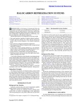
HALOCARBON REFRIGERATION SYSTEMS
Refrigerant Flow ........................................................................ 1.1
Refrigerant Line Sizing .............................................................. 1.1
Discharge (Hot-Gas) Lines ...................................................... 1.18
Defrost Gas Supply Lines......................................................... 1.20
Receivers .................................................................................. 1.21
Air-Cooled Condensers............................................................ 1.23
Piping at Multiple Compressors ..............................................
Piping at Various System Components.....................................
Refrigeration Accessories ........................................................
Pressure Control for Refrigerant Condensers..........................
Keeping Liquid from Crankcase During Off Cycles ................
Hot-Gas Bypass Arrangements ................................................
R
Licensed for single user. © 2010 ASHRAE, Inc.
EFRIGERATION is the process of moving heat from one
location to another by use of refrigerant in a closed cycle. Oil
management; gas and liquid separation; subcooling, superheating,
and piping of refrigerant liquid and gas; and two-phase flow are all
part of refrigeration. Applications include air conditioning, commercial refrigeration, and industrial refrigeration.
Desired characteristics of a refrigeration system may include
Table 1
Recommended Gas Line Velocities
Suction line
4.5 to 20 m/s
Discharge line
10 to 18 m/s
low initial cost of the system may be more significant than low
operating cost. Industrial or commercial refrigeration applications,
where equipment runs almost continuously, should be designed
with low refrigerant velocities for most efficient compressor performance and low equipment operating costs. An owning and operating cost analysis will reveal the best choice of line sizes. (See
Chapter 36 of the 2007 ASHRAE Handbook—HVAC Applications
for information on owning and operating costs.) Liquid lines from
condensers to receivers should be sized for 0.5 m/s or less to ensure
positive gravity flow without incurring backup of liquid flow. Liquid lines from receiver to evaporator should be sized to maintain
velocities below 1.5 m/s, thus minimizing or preventing liquid
hammer when solenoids or other electrically operated valves are
used.
• Year-round operation, regardless of outdoor ambient conditions
• Possible wide load variations (0 to 100% capacity) during short
periods without serious disruption of the required temperature
levels
• Frost control for continuous-performance applications
• Oil management for different refrigerants under varying load and
temperature conditions
• A wide choice of heat exchange methods (e.g., dry expansion,
liquid overfeed, or flooded feed of the refrigerants) and use of secondary coolants such as salt brine, alcohol, and glycol
• System efficiency, maintainability, and operating simplicity
• Operating pressures and pressure ratios that might require multistaging, cascading, and so forth
Refrigerant Flow Rates
Refrigerant flow rates for R-22 and R-134a are indicated in Figures 1 and 2. To obtain total system flow rate, select the proper rate
value and multiply by system capacity. Enter curves using saturated refrigerant temperature at the evaporator outlet and actual
liquid temperature entering the liquid feed device (including subcooling in condensers and liquid-suction interchanger, if used).
Because Figures 1 and 2 are based on a saturated evaporator
temperature, they may indicate slightly higher refrigerant flow rates
than are actually in effect when suction vapor is superheated above
the conditions mentioned. Refrigerant flow rates may be reduced
approximately 0.5% for each 1 K increase in superheat in the evaporator.
Suction-line superheating downstream of the evaporator from
line heat gain from external sources should not be used to reduce
evaluated mass flow, because it increases volumetric flow rate and
line velocity per unit of evaporator capacity, but not mass flow rate.
It should be considered when evaluating suction-line size for satisfactory oil return up risers.
Suction gas superheating from use of a liquid-suction heat
exchanger has an effect on oil return similar to that of suction-line
superheating. The liquid cooling that results from the heat exchange
reduces mass flow rate per ton of refrigeration. This can be seen in
Figures 1 and 2 because the reduced temperature of the liquid supplied to the evaporator feed valve has been taken into account.
Superheat caused by heat in a space not intended to be cooled is
always detrimental because the volumetric flow rate increases with
no compensating gain in refrigerating effect.
A successful refrigeration system depends on good piping design
and an understanding of the required accessories. This chapter covers the fundamentals of piping and accessories in halocarbon refrigerant systems. Hydrocarbon refrigerant pipe friction data can be
found in petroleum industry handbooks. Use the refrigerant properties and information in Chapters 3, 29, and 30 of the 2009 ASHRAE
Handbook—Fundamentals to calculate friction losses.
For information on refrigeration load, see Chapter 22. For R-502
information, refer to the 1998 ASHRAE Handbook—Refrigeration.
Piping Basic Principles
The design and operation of refrigerant piping systems should
(1) ensure proper refrigerant feed to evaporators; (2) provide practical refrigerant line sizes without excessive pressure drop; (3) prevent excessive amounts of lubricating oil from being trapped in any
part of the system; (4) protect the compressor at all times from loss
of lubricating oil; (5) prevent liquid refrigerant or oil slugs from entering the compressor during operating and idle time; and (6) maintain a clean and dry system.
REFRIGERANT FLOW
Refrigerant Line Velocities
Economics, pressure drop, noise, and oil entrainment establish
feasible design velocities in refrigerant lines (Table 1).
Higher gas velocities are sometimes found in relatively short
suction lines on comfort air-conditioning or other applications
where the operating time is only 2000 to 4000 h per year and where
REFRIGERANT LINE SIZING
In sizing refrigerant lines, cost considerations favor minimizing
line sizes. However, suction and discharge line pressure drops cause
The preparation of this chapter is assigned to TC 10.3, Refrigerant Piping.
1.1
Copyright © 2010, ASHRAE
1.24
1.25
1.28
1.32
1.33
1.34
This file is licensed to Abdual Hadi Nema (). License Date: 6/1/2010
1.2
2010 ASHRAE Handbook—Refrigeration (SI)
Fig. 1 Flow Rate per Ton of Refrigeration for Refrigerant 22
Table 2 Approximate Effect of Gas Line Pressure Drops on
R-22 Compressor Capacity and Powera
Capacity, %
Energy, %b
Suction Line
0
1
2
100
96.8
93.6
100
104.3
107.3
Discharge Line
0
1
2
100
99.2
98.4
100
102.7
105.7
Line Loss, K
aFor system operating at 5°C saturated evaporator temperature and 40°C saturated con-
densing temperature.
percentage rated at kW (power)/kW (cooling).
bEnergy
Licensed for single user. © 2010 ASHRAE, Inc.
Fig. 1
Fig. 2
134a
Flow Rate per Kilowatt of Refrigeration for
Refrigerant 22
Flow Rate per Ton of Refrigeration for Refrigerant
Liquid subcooling is the only method of overcoming liquid line
pressure loss to guarantee liquid at the expansion device in the evaporator. If subcooling is insufficient, flashing occurs in the liquid line
and degrades system efficiency.
Friction pressure drops in the liquid line are caused by accessories such as solenoid valves, filter-driers, and hand valves, as well as
by the actual pipe and fittings between the receiver outlet and the
refrigerant feed device at the evaporator.
Liquid-line risers are a source of pressure loss and add to the
total loss of the liquid line. Loss caused by risers is approximately
11.3 kPa per metre of liquid lift. Total loss is the sum of all friction
losses plus pressure loss from liquid risers.
Example 1 illustrates the process of determining liquid-line size
and checking for total subcooling required.
Example 1. An R-22 refrigeration system using copper pipe operates at
5°C evaporator and 40°C condensing. Capacity is 14 kW, and the liquid
line is 50 m equivalent length with a riser of 6 m. Determine the liquidline size and total required subcooling.
Solution: From Table 3, the size of the liquid line at 1 K drop is 15 mm
OD. Use the equation in Note 3 of Table 3 to compute actual temperature drop. At 14 kW,
Fig. 2
Flow Rate per Kilowatt of Refrigeration for
Refrigerant 134a
loss of compressor capacity and increased power usage. Excessive
liquid line pressure drops can cause liquid refrigerant to flash,
resulting in faulty expansion valve operation. Refrigeration systems
are designed so that friction pressure losses do not exceed a pressure
differential equivalent to a corresponding change in the saturation
boiling temperature. The primary measure for determining pressure
drops is a given change in saturation temperature.
Pressure Drop Considerations
Pressure drop in refrigerant lines reduces system efficiency. Correct sizing must be based on minimizing cost and maximizing efficiency. Table 2 shows the approximate effect of refrigerant pressure
drop on an R-22 system operating at a 5°C saturated evaporator temperature with a 40°C saturated condensing temperature.
Pressure drop calculations are determined as normal pressure loss
associated with a change in saturation temperature of the refrigerant.
Typically, the refrigeration system is sized for pressure losses of 1 K
or less for each segment of the discharge, suction, and liquid lines.
Liquid Lines. Pressure drop should not be so large as to cause
gas formation in the liquid line, insufficient liquid pressure at the
liquid feed device, or both. Systems are normally designed so that
pressure drop in the liquid line from friction is not greater than that
corresponding to about a 0.5 to 1 K change in saturation temperature. See Tables 3 to 9 for liquid-line sizing information.
Actual temperature drop = (50 0.02)(14.0/21.54)1.8
Estimated friction loss
= 0.46(50 × 0.749)
Loss for the riser
= 6 11.3
Total pressure losses
= 67.8 + 17.2
Saturation pressure at 40°C condensing
(see R-22 properties in Chapter 30, 2009 ASHRAE
Handbook—Fundamentals)
Initial pressure at beginning of liquid line
Total liquid line losses
Net pressure at expansion device
The saturation temperature at 1449.1 kPa is 37.7°C.
Required subcooling to overcome the liquid losses
=
0.46 K
=
17.2 kPa
=
67.8 kPa
=
85.0 kPa
= 1534.1 kPa
1534.1 kPa
–
85.0 kPa
= 1449.1 kPa
= (40.0 – 37.7)
or 2.3 K
Refrigeration systems that have no liquid risers and have the
evaporator below the condenser/receiver benefit from a gain in pressure caused by liquid weight and can tolerate larger friction losses
without flashing. Regardless of the liquid-line routing when flashing occurs, overall efficiency is reduced, and the system may malfunction.
The velocity of liquid leaving a partially filled vessel (e.g., a
receiver or shell-and-tube condenser) is limited by the height of the
liquid above the point at which the liquid line leaves the vessel,
whether or not the liquid at the surface is subcooled. Because liquid
in the vessel has a very low (or zero) velocity, the velocity V in the
liquid line (usually at the vena contracta) is V 2 = 2gh, where h is
the liquid height in the vessel. Gas pressure does not add to the
velocity unless gas is flowing in the same direction. As a result, both
gas and liquid flow through the line, limiting the rate of liquid flow.
This file is licensed to Abdual Hadi Nema (). License Date: 6/1/2010
Halocarbon Refrigeration Systems
Table 3
Suction, Discharge, and Liquid Line Capacities in Kilowatts for Refrigerant 22 (Single- or High-Stage Applications)
–40
Nominal
Line
OD, mm
Licensed for single user. © 2010 ASHRAE, Inc.
1.3
196
12
15
18
22
28
35
42
54
67
79
105
0.32
0.61
1.06
1.88
3.73
6.87
11.44
22.81
40.81
63.34
136.0
10
15
20
25
32
40
50
65
80
100
0.47
0.88
1.86
3.52
7.31
10.98
21.21
33.84
59.88
122.3
Suction Lines (t = 0.04 K/m)
Discharge Lines
Saturated Suction Temperature, °C
(t = 0.02 K/m, p = 74.90)
–30
–20
–5
5
Saturated Suction
Corresponding p, Pa/m
Temperature, °C
277
378
572
731
–40
–20
5
TYPE L COPPER LINE
0.50
0.75
1.28
1.76
2.30
2.44
2.60
0.95
1.43
2.45
3.37
4.37
4.65
4.95
1.66
2.49
4.26
5.85
7.59
8.06
8.59
2.93
4.39
7.51
10.31
13.32
14.15
15.07
5.82
8.71
14.83
20.34
26.24
27.89
29.70
10.70
15.99
27.22
37.31
48.03
51.05
54.37
17.80
26.56
45.17
61.84
79.50
84.52
90.00
35.49
52.81
89.69
122.7
157.3
167.2
178.1
63.34
94.08
159.5
218.3
279.4
297.0
316.3
98.13
145.9
247.2
337.9
431.3
458.5
488.2
210.3
312.2
527.8
721.9
919.7
977.6
1041.0
STEEL LINE
0.72
1.06
1.78
2.42
3.04
3.23
3.44
1.35
1.98
3.30
4.48
5.62
5.97
6.36
2.84
4.17
6.95
9.44
11.80
12.55
13.36
5.37
7.87
13.11
17.82
22.29
23.70
25.24
11.12
16.27
27.11
36.79
46.04
48.94
52.11
16.71
24.45
40.67
55.21
68.96
73.31
78.07
32.23
47.19
78.51
106.4
132.9
141.3
150.5
51.44
75.19
124.8
169.5
211.4
224.7
239.3
90.95
132.8
220.8
299.5
373.6
397.1
422.9
185.6
270.7
450.1
610.6
761.7
809.7
862.2
Notes:
1. Table capacities are in kilowatts of refrigeration.
p = pressure drop per unit equivalent length of line, Pa/m
t = corresponding change in saturation temperature, K/m
2. Line capacity for other saturation temperatures t and equivalent lengths Le
Velocity =
0.5 m/s
t =
0.02 K/m
p = 749
7.08
11.49
17.41
26.66
44.57
70.52
103.4
174.1
269.9
376.5
672.0
11.24
21.54
37.49
66.18
131.0
240.7
399.3
794.2
1415.0
2190.9
4697.0
10.66
16.98
29.79
48.19
83.56
113.7
187.5
267.3
412.7
711.2
15.96
29.62
62.55
118.2
244.4
366.6
707.5
1127.3
1991.3
4063.2
4. Values based on 40°C condensing temperature. Multiply table capacities by
the following factors for other condensing temperatures.
Table L e Actual t 0.55
Line capacity = Table capacity ----------------------- -----------------------
Actual L e Table t
3. Saturation temperature t for other capacities and equivalent lengths Le
Actual L
Actual capacity 1.8
t = Table t -----------------------e -------------------------------------
Table L e Table capacity
a Sizing is recommended where any gas generated in receiver must return up condensate line to
condenser without restricting condensate flow. Water-cooled condensers, where receiver ambient
temperature may be higher than refrigerant condensing temperature, fall into this category.
Table 4
Liquid Lines
See note a
Condensing
Temperature, °C
20
30
40
50
Suction
Line
1.18
1.10
1.00
0.91
Discharge
Line
0.80
0.88
1.00
1.11
pressure drop p is conservative; if subcooling is substantial or line is
short, a smaller size line may be used. Applications with very little subcooling or very long lines may require a larger line.
b Line
Suction, Discharge, and Liquid Line Capacities in Kilowatts for Refrigerant 22 (Intermediate- or Low-Stage Duty)
Nominal
Type L
Copper Line
OD, mm
12
15
18
22
28
35
42
54
67
79
105
130
156
–70
31.0
0.09
0.17
0.29
0.52
1.05
1.94
3.26
6.54
11.77
18.32
39.60
70.87
115.74
Suction Lines (t = 0.04 K/m)
Saturated Suction Temperature, °C
–60
–50
–40
Corresponding p, Pa/m
51.3
81.5
121
0.16
0.27
0.47
0.31
0.52
0.90
0.55
0.91
1.57
0.97
1.62
2.78
1.94
3.22
5.52
3.60
5.95
10.17
6.00
9.92
16.93
12.03
19.83
33.75
21.57
35.47
60.38
33.54
55.20
93.72
72.33
118.66
201.20
129.17
211.70
358.52
210.83
344.99
583.16
Notes:
1. Table capacities are in kilowatts of refrigeration.
p = pressure drop per equivalent line length, Pa/m
t = corresponding change in saturation temperature, K/m
2. Line capacity for other saturation temperatures t and equivalent lengths Le
Table L
Actual t 0.55
Line capacity = Table capacity ----------------------e- -----------------------
Actual L e Table t
3. Saturation temperature t for other capacities and equivalent lengths Le
Actual L
Actual capacity 1.8
t = Table t -----------------------e -------------------------------------
Table L e
Table capacity
*See the section on Pressure Drop Considerations.
–30
228
0.73
1.39
2.43
4.30
8.52
15.68
26.07
51.98
92.76
143.69
308.02
548.66
891.71
Discharge
Lines*
0.74
1.43
2.49
4.41
8.74
16.08
26.73
53.28
95.06
174.22
316.13
561.89
915.02
Liquid
Lines
See Table 3
4. Refer to refrigerant property tables (Chapter 30 of the 2009 ASHRAE Handbook—Fundamentals) for pressure drop corresponding to t.
5. Values based on –15°C condensing temperature. Multiply table capacities by the
following factors for other condensing temperatures.
Condensing
Temperature, °C
Suction Line
Discharge Line
–30
1.08
0.74
–20
1.03
0.91
–10
0.98
1.09
0
0.91
1.29
This file is licensed to Abdual Hadi Nema (). License Date: 6/1/2010
1.4
2010 ASHRAE Handbook—Refrigeration (SI)
If this factor is not considered, excess operating charges in receivers
and flooding of shell-and-tube condensers may result.
No specific data are available to precisely size a line leaving a
vessel. If the height of liquid above the vena contracta produces the
desired velocity, liquid leaves the vessel at the expected rate. Thus,
if the level in the vessel falls to one pipe diameter above the bottom
of the vessel from which the liquid line leaves, the capacity of copper lines for R-22 at 6.4 g/s per kilowatt of refrigeration is approximately as follows:
OD, mm
kW
28
35
42
54
67
79
105
49
88
140
280
460
690
1440
Licensed for single user. © 2010 ASHRAE, Inc.
The whole liquid line need not be as large as the leaving connection. After the vena contracta, the velocity is about 40% less. If the
line continues down from the receiver, the value of h increases. For
a 700 kW capacity with R-22, the line from the bottom of the
receiver should be about 79 mm. After a drop of 1300 mm, a reduction to 54 mm is satisfactory.
Suction Lines. Suction lines are more critical than liquid and
discharge lines from a design and construction standpoint. Refrigerant lines should be sized to (1) provide a minimum pressure drop
at full load, (2) return oil from the evaporator to the compressor
under minimum load conditions, and (3) prevent oil from draining
from an active evaporator into an idle one. A pressure drop in the
suction line reduces a system’s capacity because it forces the compressor to operate at a lower suction pressure to maintain a desired
evaporating temperature in the coil. The suction line is normally
sized to have a pressure drop from friction no greater than the
equivalent of about a 1 K change in saturation temperature. See
Tables 3 to 15 for suction line sizing information.
At suction temperatures lower than 5°C, the pressure drop
equivalent to a given temperature change decreases. For example,
at –40°C suction with R-22, the pressure drop equivalent to a 1 K
change in saturation temperature is about 4.9 kPa. Therefore,
low-temperature lines must be sized for a very low pressure drop,
or higher equivalent temperature losses, with resultant loss in
equipment capacity, must be accepted. For very low pressure
drops, any suction or hot-gas risers must be sized properly to
Table 5 Suction, Discharge, and Liquid Line Capacities in Kilowatts for Refrigerant 134a (Single- or High-Stage Applications)
Suction Lines (t = 0.04 K/m)
–10
–5
0
5
10
487
555
Nominal
Line OD,
mm
318
368
425
12
15
18
22
28
35
42
54
67
79
105
0.62
1.18
2.06
3.64
7.19
13.20
21.90
43.60
77.70
120.00
257.00
0.76
1.45
2.52
4.45
8.80
16.10
26.80
53.20
94.60
147.00
313.00
0.92
1.76
3.60
5.40
10.70
19.50
32.40
64.40
115.00
177.00
379.00
1.11
2.12
3.69
6.50
12.80
23.50
39.00
77.30
138.00
213.00
454.00
10
15
20
25
32
40
50
65
80
100
0.87
1.62
3.41
6.45
13.30
20.00
38.60
61.50
109.00
222.00
1.06
1.96
4.13
7.81
16.10
24.20
46.70
74.30
131.00
268.00
1.27
2.36
4.97
9.37
19.40
29.10
56.00
89.30
158.00
322.00
1.52
2.81
5.93
11.20
23.10
34.60
66.80
106.00
288.00
383.00
Liquid Lines
Discharge Lines
(t = 0.02 K/m, p = 538 Pa/m)
Saturated Suction Temperature, °C
Saturated Suction
Temperature, °C
Corresponding p, Pa/m
See note a
–10
0
10
Velocity =
0.5 m/s
t = 0.02 K/m
p = 538 Pa/m
1.69
3.23
5.61
9.87
19.50
35.60
59.00
117.00
208.00
321.00
686.00
1.77
3.37
5.85
10.30
20.30
37.20
61.60
122.00
217.00
335.00
715.00
1.84
3.51
6.09
10.70
21.10
38.70
64.10
127.00
226.00
349.00
744.00
6.51
10.60
16.00
24.50
41.00
64.90
95.20
160.00
248.00
346.00
618.00
8.50
16.30
28.40
50.10
99.50
183.00
304.00
605.00
1080.00
1670.00
3580.00
2.28
4.22
8.88
16.70
34.60
51.90
100.00
159.00
281.00
573.00
2.38
4.40
9.26
17.50
36.10
54.10
104.00
166.00
294.00
598.00
2.47
4.58
9.64
18.20
37.50
56.30
108.00
173.00
306.00
622.00
9.81
15.60
27.40
44.40
76.90
105.00
173.00
246.00
380.00
655.00
12.30
22.80
48.20
91.00
188.00
283.00
546.00
871.00
1540.00
3140.00
TYPE L COPPER LINE
1.33
2.54
4.42
7.77
15.30
28.10
46.50
92.20
164.00
253.00
541.00
STEEL LINE
1.80
3.34
7.02
13.30
27.40
41.00
79.10
126.00
223.00
454.00
Notes:
1. Table capacities are in kilowatts of refrigeration.
p = pressure drop per equivalent line length, Pa/m
t = corresponding change in saturation temperature, K/m
2. Line capacity for other saturation temperatures t and equivalent lengths Le
Table L
Actual t 0.55
Line capacity = Table capacity ----------------------e- -----------------------
Actual L e Table t
3. Saturation temperature t for other capacities and equivalent lengths Le
Actual L
Actual capacity 1.8
t = Table t -----------------------e -------------------------------------
Table L e Table capacity
a Sizing
is recommended where any gas generated in receiver must return up condensate line to condenser without restricting condensate flow. Water-cooled condensers, where receiver ambient temperature may be higher than refrigerant condensing temperature, fall into this category.
4. Values based on 40°C condensing temperature. Multiply table capacities
by the following factors for other condensing temperatures.
Condensing
Temperature, °C
20
30
40
50
Suction
Line
1.239
1.120
1.0
0.888
Discharge
Line
0.682
0.856
1.0
1.110
pressure drop p is conservative; if subcooling is substantial or line
is short, a smaller size line may be used. Applications with very little
subcooling or very long lines may require a larger line.
b Line
This file is licensed to Abdual Hadi Nema (). License Date: 6/1/2010
Halocarbon Refrigeration Systems
ensure oil entrainment up the riser so that oil is always returned
to the compressor.
Where pipe size must be reduced to provide sufficient gas velocity to entrain oil up vertical risers at partial loads, greater pressure
drops are imposed at full load. These can usually be compensated
for by oversizing the horizontal and down run lines and components.
Discharge Lines. Pressure loss in hot-gas lines increases the
required compressor power per unit of refrigeration and decreases
compressor capacity. Table 2 illustrates power losses for an R-22
system at 5°C evaporator and 40°C condensing temperature. Pressure drop is minimized by generously sizing lines for low friction
losses, but still maintaining refrigerant line velocities to entrain and
carry oil along at all loading conditions. Pressure drop is normally
designed not to exceed the equivalent of a 1 K change in saturation
temperature. Recommended sizing tables are based on a 0.02 K/m
change in saturation temperature.
Licensed for single user. © 2010 ASHRAE, Inc.
Location and Arrangement of Piping
Refrigerant lines should be as short and direct as possible to
minimize tubing and refrigerant requirements and pressure drops.
Plan piping for a minimum number of joints using as few elbows
and other fittings as possible, but provide sufficient flexibility to
absorb compressor vibration and stresses caused by thermal expansion and contraction.
Arrange refrigerant piping so that normal inspection and servicing of the compressor and other equipment is not hindered. Do not
obstruct the view of the oil-level sight glass or run piping so that it
interferes with removing compressor cylinder heads, end bells,
access plates, or any internal parts. Suction-line piping to the compressor should be arranged so that it will not interfere with removal
of the compressor for servicing.
Provide adequate clearance between pipe and adjacent walls and
hangers or between pipes for insulation installation. Use sleeves that
are sized to permit installation of both pipe and insulation through
floors, walls, or ceilings. Set these sleeves prior to pouring of concrete or erection of brickwork.
Run piping so that it does not interfere with passages or obstruct
headroom, windows, and doors. Refer to ASHRAE Standard 15 and
other governing local codes for restrictions that may apply.
Protection Against Damage to Piping
Protection against damage is necessary, particularly for small
lines, which have a false appearance of strength. Where traffic is
heavy, provide protection against impact from carelessly handled
hand trucks, overhanging loads, ladders, and fork trucks.
Piping Insulation
All piping joints and fittings should be thoroughly leak-tested
before insulation is sealed. Suction lines should be insulated to prevent sweating and heat gain. Insulation covering lines on which
moisture can condense or lines subjected to outside conditions must
be vapor-sealed to prevent any moisture travel through the insulation or condensation in the insulation. Many commercially available
types are provided with an integral waterproof jacket for this purpose. Although the liquid line ordinarily does not require insulation,
suction and liquid lines can be insulated as a unit on installations
where the two lines are clamped together. When it passes through a
warmer area, the liquid line should be insulated to minimize heat
gain. Hot-gas discharge lines usually are not insulated; however,
they should be insulated if the heat dissipated is objectionable or to
prevent injury from high-temperature surfaces. In the latter case, it
is not essential to provide insulation with a tight vapor seal because
moisture condensation is not a problem unless the line is located
outside. Hot-gas defrost lines are customarily insulated to minimize
heat loss and condensation of gas inside the piping.
1.5
All joints and fittings should be covered, but it is not advisable to
do so until the system has been thoroughly leak-tested. See Chapter
10 for additional information.
Vibration and Noise in Piping
Vibration transmitted through or generated in refrigerant piping
and the resulting objectionable noise can be eliminated or minimized by proper piping design and support.
Two undesirable effects of vibration of refrigerant piping are
(1) physical damage to the piping, which can break brazed joints
and, consequently, lose charge; and (2) transmission of noise
through the piping itself and through building construction that
may come into direct contact with the piping.
In refrigeration applications, piping vibration can be caused by
rigid connection of the refrigerant piping to a reciprocating compressor. Vibration effects are evident in all lines directly connected to the
compressor or condensing unit. It is thus impossible to eliminate
vibration in piping; it is only possible to mitigate its effects.
Flexible metal hose is sometimes used to absorb vibration transmission along smaller pipe sizes. For maximum effectiveness, it
should be installed parallel to the crankshaft. In some cases, two
isolators may be required, one in the horizontal line and the other
in the vertical line at the compressor. A rigid brace on the end of the
flexible hose away from the compressor is required to prevent
vibration of the hot-gas line beyond the hose.
Flexible metal hose is not as efficient in absorbing vibration on
larger pipes because it is not actually flexible unless the ratio of
length to diameter is relatively great. In practice, the length is often
limited, so flexibility is reduced in larger sizes. This problem is best
solved by using flexible piping and isolation hangers where the piping is secured to the structure.
When piping passes through walls, through floors, or inside furring, it must not touch any part of the building and must be supported only by the hangers (provided to avoid transmitting vibration
to the building); this eliminates the possibility of walls or ceilings
acting as sounding boards or diaphragms. When piping is erected
where access is difficult after installation, it should be supported by
isolation hangers.
Vibration and noise from a piping system can also be caused by
gas pulsations from the compressor operation or from turbulence in
the gas, which increases at high velocities. It is usually more apparent in the discharge line than in other parts of the system.
When gas pulsations caused by the compressor create vibration and noise, they have a characteristic frequency that is a function of the number of gas discharges by the compressor on each
revolution. This frequency is not necessarily equal to the number
of cylinders, because on some compressors two pistons operate
together. It is also varied by the angular displacement of the cylinders, such as in V-type compressors. Noise resulting from gas
pulsations is usually objectionable only when the piping system
amplifies the pulsation by resonance. On single-compressor systems, resonance can be reduced by changing the size or length of
the resonating line or by installing a properly sized hot-gas muffler in the discharge line immediately after the compressor discharge valve. On a paralleled compressor system, a harmonic
frequency from the different speeds of multiple compressors may
be apparent. This noise can sometimes be reduced by installing
mufflers.
When noise is caused by turbulence and isolating the line is not
effective enough, installing a larger-diameter pipe to reduce gas
velocity is sometimes helpful. Also, changing to a line of heavier
wall or from copper to steel to change the pipe natural frequency
may help.
Refrigerant Line Capacity Tables
Tables 3 to 9 show line capacities in kilowatts of refrigeration for
R-22, R-134a, R-404A, R-507A, R-410A, and R-407C. Capacities
This file is licensed to Abdual Hadi Nema (). License Date: 6/1/2010
Type L
Copper,
OD,
mm
12
15
18
22
28
35
42
54
67
79
105
130
156
206
257
Steel
mm SCH
10 80
15 80
20 80
25 80
32 80
40 80
50 40
65 40
80 40
100 40
125 40
150 40
200 40
250 40
300 IDb
350 30
400 30
a Sizing
–50
165.5
0.16
0.30
0.53
0.94
1.86
3.43
5.71
11.37
20.31
31.54
67.66
120.40
195.94
401.89
715.93
0.16
0.31
0.70
1.37
2.95
4.49
10.47
16.68
29.51
60.26
108.75
176.25
360.41
652.69
1044.01
1351.59
1947.52
Suction Lines (t = 0.04 K/m)
Discharge Lines (t = 0.02 K/m, p = 74.90)
Saturated Suction Temperature, °C
–40
–30
–20
–5
Corresponding p, Pa/m
240.6
337.2
455.1
679.1
0.27
0.43
0.67
1.19
0.52
0.83
1.28
2.27
0.90
1.45
2.22
3.94
1.59
2.55
3.91
6.93
3.14
5.04
7.72
13.66
5.78
9.26
14.15
25.00
9.61
15.36
23.46
41.32
19.12
30.50
46.57
81.90
34.10
54.30
82.75
145.45
52.78
84.12
128.09
224.52
113.08
179.89
273.26
478.70
201.19
319.22
484.40
847.54
326.58
518.54
785.73
1372.94
669.47
1059.73
1607.24
2805.00
1189.91
1885.42
2851.68
4974.31
Saturated Suction Temperature, °C
–40
–30
–20
–5
Corresponding p, Pa/m
875.6
875.6
875.6
875.6
1.87
2.00
2.13
2.31
3.55
3.81
4.05
4.40
6.16
6.59
7.02
7.62
10.79
11.56
12.30
13.36
21.23
22.74
24.21
26.29
38.78
41.54
44.23
48.03
64.15
68.72
73.16
79.45
126.86
135.89
144.67
157.11
225.07
241.08
256.66
278.73
346.97
371.66
395.67
429.70
738.92
791.51
842.65
915.11
1309.04
1402.20
1492.80
1621.17
2116.83
2267.48
2413.98
2621.57
4317.73
4625.02
4923.84
5347.26
7641.29
8185.11
8713.94
9463.30
0.26
0.51
1.15
2.25
4.83
7.38
17.16
27.33
48.38
98.60
177.97
287.77
589.35
1065.97
1705.26
2207.80
3176.58
0.40
0.80
1.80
3.53
7.57
11.55
26.81
42.72
75.47
153.84
277.71
449.08
918.60
1661.62
2658.28
3436.53
4959.92
5
–50
863.2
1.69
3.22
5.57
9.79
19.25
35.17
58.16
114.98
203.96
314.97
670.69
1188.02
1921.03
3917.77
6949.80
875.6
1.73
3.29
5.71
10.00
19.68
35.96
59.48
117.62
208.67
321.69
685.09
1213.68
1962.62
4003.19
7084.63
0.61
1.05
1.46
1.49
1.20
2.07
2.88
2.94
2.70
4.66
6.48
6.61
5.30
9.13
12.68
12.95
11.35
19.57
27.20
27.72
17.29
29.81
41.42
42.22
40.20
69.20
96.18
98.04
63.93
110.18
152.98
155.95
112.96
194.49
270.35
275.59
230.29
396.56
550.03
560.67
415.78
714.27
991.91
1012.44
671.57
1155.17
1604.32
1635.36
1373.79
2363.28
3277.89
3341.30
2485.16
4275.41
5930.04
6044.77
3970.05
6830.36
9488.03
9671.59
5140.20
8843.83 12 266.49 12 503.79
7407.49 12 725.25 17 677.86 18 019.86
shown is recommended where any gas generated
in receiver must return up condensate line to condenser
without restricting condensate flow. Water-cooled condensers, where receiver ambient temperature may be
higher than refrigerant condensing temperature, fall into
this category.
b Pipe inside diameter is same as nominal pipe size.
1.61
3.17
7.13
13.97
29.90
45.54
105.75
168.20
297.25
604.72
1091.99
1763.85
3603.84
6519.73
10 431.52
13 486.26
19 435.74
1.72
3.39
7.64
14.96
32.03
48.78
113.27
180.17
318.40
647.76
1169.71
1889.38
3860.32
6983.73
11 173.92
14 446.06
20 818.96
1.83
3.61
8.14
15.93
34.10
51.94
120.59
191.81
338.98
689.61
1245.28
2011.45
4109.73
7434.94
11 895.85
15 379.40
22 164.04
1.99
3.92
8.84
17.30
37.03
56.40
130.96
208.31
368.13
748.91
1352.37
2184.43
4463.15
8074.30
12 918.83
16 701.95
24 070.04
Liquid Lines (40°C)
See note a
5
875.6
2.42
4.61
7.99
14.01
27.57
50.37
83.32
164.76
292.29
450.60
959.63
1700.03
2749.09
5607.37
9923.61
2.09
4.12
9.27
18.14
38.83
59.14
137.33
218.44
386.03
785.34
1418.15
2290.69
4680.25
8467.06
13 547.24
17 514.38
25 240.87
t = 0.02 K/m
Drop
Velocity =
0.5 m/s
p = 875.6
4.1
8.0
6.7
15.3
10.1
26.6
15.5
46.8
26.0
92.5
41.1
169.3
60.3
280.4
101.4
556.9
157.3
989.8
219.3
1529.9
391.5
3264.9
607.3
5788.8
879.6
9382.5
1522.1
19 177.4
2366.6
33 992.3
4.6
7.6
14.1
23.4
41.8
57.5
109.2
155.7
240.5
414.3
650.6
940.3
1628.2
2566.4
3680.9
4487.7
5944.7
7.2
14.3
32.1
63.0
134.9
205.7
477.6
761.1
1344.9
2735.7
4939.2
7988.0
16 342.0
29 521.7
47 161.0
61 061.2
87 994.9
t = 0.05 K/m
Drop
p = 2189.1
13.3
25.2
43.7
76.7
151.1
276.3
456.2
903.2
1601.8
2473.4
5265.6
9335.2
15 109.7
30 811.3
54 651.2
11.5
22.7
51.1
100.0
214.0
326.5
758.2
1205.9
2131.2
4335.6
7819.0
12 629.7
25 838.1
46 743.9
74 677.7
96 691.3
139 346.8
4. Capacity (kW) based on standard refrigerant cycle of 40°C liquid and Cond. SucNotes:
saturated evaporator outlet temperature. Liquid capacity (kW) based Temp., tion
1. Table capacities are in kilowatts of refrigeration.
on –5°C evaporator temperature.
p = pressure drop per unit equivalent length of line, Pa/m
°C
Line
5. Thermophysical properties and viscosity data based on calculations
t = corresponding change in saturation temperature, K/m
20
1.344
from NIST REFPROP program Version 6.01.
2. Line capacity for other saturation temperatures t and equivalent lengths Le
30
1.177
6. For brazed Type L copper tubing larger than 28 mm OD for discharge
Table L
Actual t 0.55
Line capacity = Table capacity ----------------------e- -----------------------
40
1.000
or liquid service, see Safety Requirements section.
Actual L e Table t
7. Values are based on 40°C condensing temperature. Multiply table
50
0.809
3. Saturation temperature t for other capacities and equivalent lengths Le
capacities by the following factors for other condensing temperatures.
1.8
Actual
L
Actual
capacity
e
t = Table t ----------------------- -------------------------------------
Table L e Table capacity
Discharge
Line
0.812
0.906
1.000
1.035
2010 ASHRAE Handbook—Refrigeration (SI)
Licensed for single user. © 2010 ASHRAE, Inc.
Line Size
SI
1.6
Table 6 Suction, Discharge, and Liquid Line Capacities in Kilowatts for Refrigerant 404A (Single- or High-Stage Applications)
This file is licensed to Abdual Hadi Nema (). License Date: 6/1/2010
Licensed for single user. © 2010 ASHRAE, Inc.
Type L
Copper,
OD,
mm
12
15
18
22
28
35
42
54
67
79
105
130
156
206
257
Steel
mm SCH
10 80
15 80
20 80
25 80
32 80
40 80
50 40
65 40
80 40
100 40
125 40
150 40
200 40
250 40
300 IDb
350 30
400 30
a Sizing
–50
173.7
0.16
0.31
0.55
0.97
1.91
3.52
5.86
11.68
20.86
32.31
69.31
123.41
200.86
412.07
733.42
0.16
0.31
0.71
1.40
3.01
4.59
10.69
17.06
30.20
61.60
111.17
179.98
368.55
666.52
1067.53
1380.23
1991.54
Suction Lines (t = 0.04 K/m)
Discharge Lines (t = 0.02 K/m, p = 74.90)
Saturated Suction Temperature, °C
–40
–30
–20
–5
Corresponding p, Pa/m
251.7
350.3
471.6
700.5
0.28
0.44
0.68
1.21
0.53
0.85
1.30
2.31
0.92
1.47
2.26
4.00
1.63
2.60
3.98
7.02
3.22
5.14
7.85
13.83
5.91
9.42
14.37
25.28
9.82
15.65
23.83
41.86
19.55
31.07
47.24
82.83
34.83
55.25
84.08
147.12
54.01
85.61
129.94
227.12
115.54
182.78
277.24
484.29
205.61
325.01
492.45
857.55
333.77
526.96
797.36
1389.26
683.01
1078.30
1631.18
2832.25
1216.78
1916.48
2891.11
5022.65
Saturated Suction Temperature, °C
–40
–30
–20
–5
Corresponding p, Pa/m
896.3
896.3
896.3
896.3
1.86
2.00
2.13
2.32
3.54
3.80
4.05
4.41
6.12
6.57
7.01
7.63
10.73
11.52
12.29
13.37
21.12
22.67
24.18
26.31
38.58
41.42
44.17
48.07
63.82
68.52
73.07
79.52
126.22
135.51
144.51
157.26
223.53
239.99
255.92
278.52
345.26
370.68
395.29
430.19
733.87
787.90
840.21
914.39
1300.07
1395.78
1488.45
1619.87
2104.68
2259.62
2409.65
2622.39
4288.18
4603.88
4909.55
5343.00
7598.35
8157.74
8699.37
9467.42
0.26
0.52
1.17
2.29
4.93
7.52
17.50
27.88
49.26
100.39
181.20
292.99
600.02
1085.29
1736.16
2247.80
3239.15
0.41
0.81
1.83
3.58
7.68
11.72
27.25
43.32
76.63
156.20
281.64
455.44
931.61
1685.18
2695.93
3485.20
5030.17
shown is recommended where any gas generated
in receiver must return up condensate line to condenser
without restricting condensate flow. Water-cooled condensers, where receiver ambient temperature may be
higher than refrigerant condensing temperature, fall into
this category.
b Pipe inside diameter is same as nominal pipe size.
0.62
1.21
2.74
5.36
11.50
17.54
40.71
64.81
114.52
233.20
421.03
680.92
1393.04
2516.51
4020.13
5205.04
7500.91
1.06
2.09
4.71
9.23
19.76
30.09
69.87
111.37
196.37
400.40
721.18
1166.35
2386.16
4316.82
6896.51
8929.47
12 848.49
5
–50
882.5
1.70
3.24
5.61
9.85
19.38
35.40
58.55
115.76
205.36
317.17
675.47
1194.03
1935.01
3937.64
6984.91
896.3
1.72
3.27
5.66
9.93
19.53
35.68
59.03
116.74
206.75
319.34
678.77
1202.46
1946.66
3966.22
7027.87
1.47
2.90
6.52
12.77
27.33
41.63
96.67
153.76
271.72
552.81
998.16
1612.43
3294.46
5960.02
9535.99
12 328.49
17 767.21
1.48
2.91
6.55
12.83
27.47
41.83
97.14
154.51
273.05
555.50
1003.06
1620.28
3310.49
5989.03
9582.41
12 388.50
17 853.70
1.60
3.15
7.09
13.87
29.70
45.23
105.02
167.05
295.22
600.59
1084.49
1751.80
3579.22
6475.19
10 360.26
13 394.13
19 302.97
1.72
3.38
7.61
14.89
31.88
48.56
112.76
179.35
316.95
644.81
1164.33
1880.77
3842.72
6951.89
11 122.98
14 380.20
20 724.05
1.83
3.60
8.11
15.88
34.00
51.78
120.24
191.26
338.00
687.62
1241.63
2005.64
4097.86
7413.46
11 861.49
15 334.97
22 100.02
1.99
3.92
8.83
17.28
37.00
56.35
130.86
208.14
367.84
748.33
1351.25
2182.72
4459.65
8067.98
12 908.71
16 688.86
24 051.18
Liquid Lines (40°C)
See note a
5
896.3
2.43
4.63
8.01
14.04
27.63
50.47
83.50
165.12
292.43
451.67
960.06
1700.76
2753.36
5609.84
9940.23
2.09
4.12
9.27
18.15
38.85
59.17
137.39
218.54
386.21
785.70
1418.74
2291.73
4682.37
8470.90
13 553.39
17 522.33
25 252.33
t = 0.02 K/m t = 0.05 K/m
Drop
Drop
Velocity =
p = 896.3 p = 2240.8
0.5 m/s
4.0
7.9
13.0
6.5
15.0
24.7
9.8
26.1
42.8
15.0
45.9
75.1
25.1
90.5
147.8
39.7
165.6
270.0
58.2
274.8
447.1
98.0
544.0
883.9
151.9
967.0
1567.7
211.9
1497.3
2420.9
378.2
3189.5
5154.4
586.7
5666.6
9129.4
849.9
9175.8
14 793.3
30 099.9
1470.7
18 734.6
2286.7
33 285.5
53 389.2
4.4
7.4
13.6
22.6
40.3
55.6
105.5
150.4
232.3
400.3
628.6
908.5
1573.2
2479.7
3556.5
4336.1
5743.9
7.1
13.9
31.4
61.6
132.0
201.0
466.6
743.5
1313.9
2675.6
4825.1
7803.5
15 964.7
28 840.0
46 140.3
59 651.3
85 963.1
11.3
22.2
49.9
97.7
209.4
319.0
740.7
1178.1
2082.0
4235.5
7638.5
12 338.1
25 241.5
45 664.6
72 953.4
94 458.7
136 129.3
Discharge
Line
0.765
0.908
1.000
1.021
1.7
Notes:
4. Capacity (kW) based on standard refrigerant cycle of 40°C liquid and Cond. Suc1. Table capacities are in kilowatts of refrigeration.
saturated evaporator outlet temperature. Liquid capacity (kW) based Temp., tion
p = pressure drop per unit equivalent length of line, Pa/m
on –5°C evaporator temperature.
°C
Line
t = corresponding change in saturation temperature, K/m
5. Thermophysical properties and viscosity data based on calculations
20
1.357
2. Line capacity for other saturation temperatures t and equivalent lengths Le
from NIST REFPROP program Version 6.01.
30
1.184
0.55
6.
For
brazed
Type
L
copper
tubing
larger
than
28
mm
OD
for
discharge
Table L
Actual t
Line capacity = Table capacity ----------------------e- -----------------------
40
1.000
or
liquid
service,
see
Safety
Requirements
section.
Actual L e Table t
7. Values are based on 40°C condensing temperature. Multiply table
50
0.801
3. Saturation temperature t for other capacities and equivalent lengths Le
capacities by the following factors for other condensing temperatures.
1.8
Actual L
Actual capacity
t = Table t -----------------------e -------------------------------------
Table L e Table capacity
SI
Line Size
Halocarbon Refrigeration Systems
Table 7 Suction, Discharge, and Liquid Line Capacities in Kilowatts for Refrigerant 507A (Single- or High-Stage Applications)
This file is licensed to Abdual Hadi Nema (). License Date: 6/1/2010
Type L
Copper,
OD,
mm
12
15
18
22
28
35
42
54
67
79
105
130
156
206
257
Steel
mm SCH
10 80
15 80
20 80
25 80
32 80
40 80
50 40
65 40
80 40
100 40
125 40
150 40
200 40
250 40
300 IDb
350 30
400 30
a Sizing
Discharge Lines (t = 0.02 K/m, p = 74.90)
Suction Lines (t = 0.04 K/m)
218.6
0.32
0.61
1.06
1.87
3.72
6.84
11.39
22.70
40.48
62.89
134.69
240.18
390.21
800.39
1427.49
Saturated Suction Temperature, °C
–40
–30
–20
–5
Corresponding p, Pa/m
317.2
443.3
599.1
894.2
0.52
0.80
1.20
2.05
0.99
1.54
2.29
3.90
1.72
2.68
3.98
6.76
3.04
4.72
7.00
11.89
6.03
9.32
13.82
23.43
11.07
17.11
25.33
42.82
18.39
28.38
42.00
70.89
36.61
56.35
83.26
140.29
65.21
100.35
147.94
249.16
101.10
155.22
229.02
384.65
216.27
331.96
488.64
820.20
384.82
590.29
866.21
1452.34
625.92
957.07
1405.29
2352.81
1280.57
1956.28
2868.65
4796.70
2276.75
3480.75
5095.42
8506.22
1137.6
2.83
5.37
9.30
16.32
32.11
58.75
97.02
191.84
340.33
525.59
1119.32
1978.69
3206.57
6532.82
11 575.35
0.31
0.61
1.39
2.72
5.86
8.94
20.81
33.22
58.79
119.78
216.38
350.32
717.23
1297.30
2075.09
2686.45
3870.92
0.49
0.97
2.19
4.30
9.24
14.09
32.75
52.18
92.36
188.24
339.76
549.37
1125.10
2035.01
3255.45
4214.83
6064.31
2.44
4.80
10.81
21.16
45.30
68.99
160.19
254.80
450.29
916.08
1654.16
2672.01
5459.36
9876.55
15 802.42
20 429.97
29 442.67
–50
0.74
1.47
3.32
6.50
13.95
21.28
49.39
78.69
139.17
283.69
511.52
827.18
1692.00
3060.66
4896.39
6329.87
9135.88
1.08
2.14
4.82
9.45
20.26
30.91
71.75
114.11
201.84
411.01
742.06
1200.12
2451.89
4435.35
7085.49
9173.88
13 220.36
shown is recommended where any gas generated
in receiver must return up condensate line to condenser
without restricting condensate flow. Water-cooled condensers, where receiver ambient temperature may be
higher than refrigerant condensing temperature, fall into
this category.
b Pipe inside diameter is same as nominal pipe size.
1.80
3.54
7.98
15.63
33.47
50.97
118.34
188.61
332.58
678.11
1221.40
1975.34
4041.21
7310.97
11 679.95
15 122.98
21 760.24
5
1172.1
3.47
6.60
11.43
20.04
39.44
72.05
119.01
235.35
417.58
643.78
1371.21
2424.14
3928.86
7995.81
14 185.59
Saturated Suction Temperature, °C
–40
–30
–20
–5
Corresponding p, Pa/m
1172.1
1172.1
1172.1
1172.1
3.60
3.73
3.84
4.00
6.85
7.09
7.31
7.60
11.87
12.29
12.67
13.16
20.81
21.54
22.20
23.08
40.95
42.39
43.70
45.42
74.82
77.46
79.84
82.98
123.57
127.93
131.87
137.06
244.38
253.00
260.80
271.06
433.60
448.89
462.73
480.93
668.47
692.05
713.37
741.44
1423.81
1474.02
1519.45
1579.22
2517.13
2605.89
2686.20
2791.88
4079.57
4223.44
4353.60
4524.87
8302.53
8595.32
8860.22
9208.77
14 729.76 15 249.20 15 719.17 16 337.55
2.98
5.87
13.21
25.86
55.37
84.33
195.83
311.49
550.47
1121.21
2022.16
3266.45
6673.89
12 073.76
19 317.94
24 974.96
35 992.70
3.10
6.09
13.72
26.85
57.50
87.57
203.34
323.43
571.59
1164.22
2099.73
3391.75
6929.91
12 536.92
20 059.00
25 933.02
37 373.41
–50
3.21
6.31
14.20
27.80
59.53
90.66
210.51
334.84
591.74
1205.28
2173.77
3511.36
7174.29
12 979.03
20 766.37
26 847.53
38 691.36
3.31
6.50
14.64
28.66
61.36
93.45
217.00
345.16
609.98
1242.42
2240.77
3619.58
7395.39
13 379.03
21 406.37
27 674.95
39 883.80
3.44
6.76
15.22
29.79
63.77
97.13
225.54
358.74
633.98
1291.30
2328.92
3761.97
7686.32
13 905.35
22 248.47
28 763.66
41 452.79
Liquid Lines (40°C)
See note a
1172.1
4.07
7.75
13.42
23.53
46.31
84.62
139.76
276.39
490.40
756.03
1610.30
2846.83
4613.92
9390.02
16 659.10
Velocity =
0.5 m/s
6.2
10.1
15.4
23.5
39.3
62.2
91.3
153.7
238.2
332.2
592.9
919.8
1332.3
2305.4
3584.6
t = 0.02 K/m
Drop
p = 1179
14.3
27.2
47.3
83.0
163.7
299.6
495.7
982.0
1746.4
2695.2
5744.4
10 188.7
16 502.3
33 708.0
59 763.6
3.50
6.89
15.52
30.37
65.03
99.04
229.98
365.80
646.46
1316.72
2374.75
3836.01
7837.60
14 179.04
22 686.37
29 329.79
42 268.67
6.9
11.5
21.3
35.5
63.2
87.1
165.4
235.8
364.2
627.6
985.4
1424.2
2466.2
3887.3
5575.3
6797.4
9004.3
12.7
25.0
56.2
110.2
235.9
359.8
835.4
1328.6
2347.8
4787.0
8622.2
13 944.5
28 528.0
51 535.6
82 451.9
106 757.2
153 611.4
5
t = 0.05 K/m
Drop
p = 2935.8
23.5
44.6
77.2
135.3
266.4
486.0
804.1
1590.3
2816.7
4350.8
9249.0
16 386.3
26 500.6
53 996.3
95 683.0
20.1
39.6
89.1
174.5
568.9
1320.9
2101.0
3713.1
7562.8
13 639.9
22 032.9
45 016.9
81 440.3
130 304.0
168 461.9
242 779.1
Notes:
4. Capacity (kW) based on standard refrigerant cycle of 40°C liquid and Cond. Suc1. Table capacities are in kilowatts of refrigeration.
saturated evaporator outlet temperature. Liquid capacity (kW) based Temp., tion
p = pressure drop per unit equivalent length of line, Pa/m
on –5°C evaporator temperature.
°C
Line
t = corresponding change in saturation temperature, K/m
5. Thermophysical properties and viscosity data based on calculations
20
1.238
2. Line capacity for other saturation temperatures t and equivalent lengths Le
from NIST REFPROP program Version 6.01.
30
1.122
0.55
6.
For
brazed
Type
L
copper
tubing
larger
than
15
mm
OD
for
discharge
Table L e Actual t
Line capacity = Table capacity ----------------------- -----------------------
40
1.000
or
liquid
service,
see
Safety
Requirements
section.
Actual L e Table t
7. Values are based on 40°C condensing temperature. Multiply table
50
0.867
3. Saturation temperature t for other capacities and equivalent lengths Le
capacities by the following factors for other condensing temperatures.
1.8
Actual
L
Actual
capacity
t = Table t -----------------------e -------------------------------------
Table L e Table capacity
Discharge
Line
0.657
0.866
1.000
1.117
2010 ASHRAE Handbook—Refrigeration (SI)
Licensed for single user. © 2010 ASHRAE, Inc.
Line Size
SI
1.8
Table 8 Suction, Discharge, and Liquid Line Capacities in Kilowatts for Refrigerant 410A (Single- or High-Stage Applications)
This file is licensed to Abdual Hadi Nema (). License Date: 6/1/2010
Licensed for single user. © 2010 ASHRAE, Inc.
Type L
Copper,
OD,
mm
12
15
18
22
28
35
42
54
67
79
105
130
156
206
257
Steel
mm SCH
10 80
15 80
20 80
25 80
32 80
40 80
50 40
65 40
80 40
100 40
125 40
150 40
200 40
250 40
300 IDb
350 30
400 30
a Sizing
–50
173.7
0.16
0.31
0.55
0.97
1.91
3.52
5.86
11.68
20.86
32.31
69.31
123.41
200.86
412.07
733.42
0.16
0.31
0.71
1.40
3.01
4.59
10.69
17.06
30.20
61.60
111.17
179.98
368.55
666.52
1067.53
1380.23
1991.54
Suction Lines (t = 0.04 K/m)
Discharge Lines (t = 0.02 K/m, p = 74.90)
Saturated Suction Temperature, °C
–40
–30
–20
–5
Corresponding p, Pa/m
251.7
350.3
471.6
700.5
0.28
0.44
0.68
1.21
0.53
0.85
1.30
2.31
0.92
1.47
2.26
4.00
1.63
2.60
3.98
7.02
3.22
5.14
7.85
13.83
5.91
9.42
14.37
25.28
9.82
15.65
23.83
41.86
19.55
31.07
47.24
82.83
34.83
55.25
84.08
147.12
54.01
85.61
129.94
227.12
115.54
182.78
277.24
484.29
205.61
325.01
492.45
857.55
333.77
526.96
797.36
1389.26
683.01
1078.30
1631.18
2832.25
1216.78
1916.48
2891.11
5022.65
Saturated Suction Temperature, °C
–40
–30
–20
–5
Corresponding p, Pa/m
896.3
896.3
896.3
896.3
1.86
2.00
2.13
2.32
3.54
3.80
4.05
4.41
6.12
6.57
7.01
7.63
10.73
11.52
12.29
13.37
21.12
22.67
24.18
26.31
38.58
41.42
44.17
48.07
63.82
68.52
73.07
79.52
126.22
135.51
144.51
157.26
223.53
239.99
255.92
278.52
345.26
370.68
395.29
430.19
733.87
787.90
840.21
914.39
1300.07
1395.78
1488.45
1619.87
2104.68
2259.62
2409.65
2622.39
4288.18
4603.88
4909.55
5343.00
7598.35
8157.74
8699.37
9467.42
0.26
0.52
1.17
2.29
4.93
7.52
17.50
27.88
49.26
100.39
181.20
292.99
600.02
1085.29
1736.16
2247.80
3239.15
0.41
0.81
1.83
3.58
7.68
11.72
27.25
43.32
76.63
156.20
281.64
455.44
931.61
1685.18
2695.93
3485.20
5030.17
shown is recommended where any gas generated
in receiver must return up condensate line to condenser
without restricting condensate flow. Water-cooled condensers, where receiver ambient temperature may be
higher than refrigerant condensing temperature, fall into
this category.
b Pipe inside diameter is same as nominal pipe size.
0.62
1.21
2.74
5.36
11.50
17.54
40.71
64.81
114.52
233.20
421.03
680.92
1393.04
2516.51
4020.13
5205.04
7500.91
1.06
2.09
4.71
9.23
19.76
30.09
69.87
111.37
196.37
400.40
721.18
1166.35
2386.16
4316.82
6896.51
8929.47
12 848.49
5
–50
882.5
1.70
3.24
5.61
9.85
19.38
35.40
58.55
115.76
205.36
317.17
675.47
1194.03
1935.01
3937.64
6984.91
896.3
1.72
3.27
5.66
9.93
19.53
35.68
59.03
116.74
206.75
319.34
678.77
1202.46
1946.66
3966.22
7027.87
1.47
2.90
6.52
12.77
27.33
41.63
96.67
153.76
271.72
552.81
998.16
1612.43
3294.46
5960.02
9535.99
12 328.49
17 767.21
1.48
2.91
6.55
12.83
27.47
41.83
97.14
154.51
273.05
555.50
1003.06
1620.28
3310.49
5989.03
9582.41
12 388.50
17 853.70
1.60
3.15
7.09
13.87
29.70
45.23
105.02
167.05
295.22
600.59
1084.49
1751.80
3579.22
6475.19
10 360.26
13 394.13
19 302.97
1.72
3.38
7.61
14.89
31.88
48.56
112.76
179.35
316.95
644.81
1164.33
1880.77
3842.72
6951.89
11 122.98
14 380.20
20 724.05
1.83
3.60
8.11
15.88
34.00
51.78
120.24
191.26
338.00
687.62
1241.63
2005.64
4097.86
7413.46
11 861.49
15 334.97
22 100.02
1.99
3.92
8.83
17.28
37.00
56.35
130.86
208.14
367.84
748.33
1351.25
2182.72
4459.65
8067.98
12 908.71
16 688.86
24 051.18
Liquid Lines (40°C)
See note a
5
896.3
2.43
4.63
8.01
14.04
27.63
50.47
83.50
165.12
292.43
451.67
960.06
1700.76
2753.36
5609.84
9940.23
2.09
4.12
9.27
18.15
38.85
59.17
137.39
218.54
386.21
785.70
1418.74
2291.73
4682.37
8470.90
13 553.39
17 522.33
25 252.33
Velocity =
0.5 m/s
4.0
6.5
9.8
15.0
25.1
39.7
58.2
98.0
151.9
211.9
378.2
586.7
849.9
1470.7
2286.7
4.4
7.4
13.6
22.6
40.3
55.6
105.5
150.4
232.3
400.3
628.6
908.5
1573.2
2479.7
3556.5
4336.1
5743.9
t = 0.02 K/m
Drop
p = 896.3
7.9
15.0
26.1
45.9
90.5
165.6
274.8
544.0
967.0
1497.3
3189.5
5666.6
9175.8
18 734.6
33 285.5
7.1
13.9
31.4
61.6
132.0
201.0
466.6
743.5
1313.9
2675.6
4825.1
7803.5
15 964.7
28 840.0
46 140.3
59 651.3
85 963.1
t = 0.05 K/m
Drop
p = 2240.8
13.0
24.7
42.8
75.1
147.8
270.0
447.1
883.9
1567.7
2420.9
5154.4
9129.4
14 793.3
30 099.9
53 389.2
11.3
22.2
49.9
97.7
209.4
319.0
740.7
1178.1
2082.0
4235.5
7638.5
12 338.1
25 241.5
45 664.6
72 953.4
94 458.7
136 129.3
Discharge
Line
0.765
0.908
1.000
1.021
1.9
Notes:
4. Capacity (kW) based on standard refrigerant cycle of 40°C liquid and Cond. Suc1. Table capacities are in kilowatts of refrigeration.
saturated evaporator outlet temperature. Liquid capacity (kW) based Temp., tion
p = pressure drop per unit equivalent length of line, Pa/m
on –5°C evaporator temperature.
°C
Line
t = corresponding change in saturation temperature, K/m
5. Thermophysical properties and viscosity data based on calculations
20
1.357
2. Line capacity for other saturation temperatures t and equivalent lengths Le
from NIST REFPROP program Version 6.01.
30
1.184
0.55
6.
For
brazed
Type
L
copper
tubing
larger
than
28
mm
OD
for
discharge
Table L
Actual t
Line capacity = Table capacity ----------------------e- -----------------------
40
1.000
or
liquid
service,
see
Safety
Requirements
section.
Actual L e Table t
7. Values are based on 40°C condensing temperature. Multiply table
50
0.801
3. Saturation temperature t for other capacities and equivalent lengths Le
capacities by the following factors for other condensing temperatures.
1.8
Actual L
Actual capacity
t = Table t -----------------------e -------------------------------------
Table L e Table capacity
SI
Line Size
Halocarbon Refrigeration Systems
Table 9 Suction, Discharge, and Liquid Line Capacities in Kilowatts for Refrigerant 407C (Single- or High-Stage Applications)
This file is licensed to Abdual Hadi Nema (). License Date: 6/1/2010
Licensed for single user. © 2010 ASHRAE, Inc.
1.10
2010 ASHRAE Handbook—Refrigeration (SI)
in the tables are based on the refrigerant flow that develops a friction
loss, per metre of equivalent pipe length, corresponding to a 0.04 K
change in the saturation temperature (t) in the suction line, and a
0.02 K change in the discharge line. The capacities shown for liquid
lines are for pressure losses corresponding to 0.02 and 0.05 K/m
change in saturation temperature and also for velocity corresponding to 0.5 m/s. Tables 10 to 15 show capacities for the same refrigerants based on reduced suction line pressure loss corresponding to
0.02 and 0.01 K/m equivalent length of pipe. These tables may be
used when designing system piping to minimize suction line pressure drop.
The refrigerant line sizing capacity tables are based on the DarcyWeisbach relation and friction factors as computed by the Colebrook function (Colebrook 1938, 1939). Tubing roughness height is
1.5 m for copper and 46 m for steel pipe. Viscosity extrapolations
and adjustments for pressures other than 101.325 kPa were based on
correlation techniques as presented by Keating and Matula (1969).
Discharge gas superheat was 45 K for R-134a and 60 K for R-22.
The refrigerant cycle for determining capacity is based on saturated gas leaving the evaporator. The calculations neglect the presence of oil and assume nonpulsating flow.
For additional charts and discussion of line sizing refer to
Atwood (1990), Timm (1991), and Wile (1977).
Equivalent Lengths of Valves and Fittings
Refrigerant line capacity tables are based on unit pressure drop
per metre length of straight pipe, or per combination of straight pipe,
fittings, and valves with friction drop equivalent to a metre of
straight pipe.
Generally, pressure drop through valves and fittings is determined
by establishing the equivalent straight length of pipe of the same size
with the same friction drop. Line sizing tables can then be used
directly. Tables 16 to 18 give equivalent lengths of straight pipe for
various fittings and valves, based on nominal pipe sizes.
The following example illustrates the use of various tables and
charts to size refrigerant lines.
Example 2. Determine the line size and pressure drop equivalent (in
degrees) for the suction line of a 105 kW R-22 system, operating at 5°C
suction and 40°C condensing temperatures. Suction line is copper tubing, with 15 m of straight pipe and six long-radius elbows.
Solution: Add 50% to the straight length of pipe to establish a trial
equivalent length. Trial equivalent length is 151.5 = 22.5 m. From
Table 3 (for 5°C suction, 40°C condensing), 122.7 kW capacity in
54 mm OD results in a 0.04 K loss per metre equivalent length.
Straight pipe length
Six 50 mm long-radius elbows at 1.0 m each (Table 16)
=
=
15.0 m
6.0 m
Total equivalent length
=
21.0 m
t = 0.0421.0(105/122.7)1.8 = 0.63 K
Because 0.63 K is below the recommended 1 K, recompute for the next
smaller (42 mm) tube (i.e., t = 2.05 K). This temperature drop is too
large; therefore, the 54 mm tube is recommended.
Oil Management in Refrigerant Lines
Oil Circulation. All compressors lose some lubricating oil during normal operation. Because oil inevitably leaves the compressor
with the discharge gas, systems using halocarbon refrigerants must
return this oil at the same rate at which it leaves (Cooper 1971).
Oil that leaves the compressor or oil separator reaches the condenser and dissolves in the liquid refrigerant, enabling it to pass
readily through the liquid line to the evaporator. In the evaporator,
the refrigerant evaporates, and the liquid phase becomes enriched
in oil. The concentration of refrigerant in the oil depends on the
evaporator temperature and types of refrigerant and oil used. The
viscosity of the oil/refrigerant solution is determined by the system
parameters. Oil separated in the evaporator is returned to the
compressor by gravity or by drag forces of the returning gas. Oil’s
effect on pressure drop is large, increasing the pressure drop by as
much as a factor of 10 (Alofs et al. 1990).
One of the most difficult problems in low-temperature refrigeration systems using halocarbon refrigerants is returning lubrication
oil from the evaporator to the compressors. Except for most centrifugal compressors and rarely used nonlubricated compressors, refrigerant continuously carries oil into the discharge line from the
compressor. Most of this oil can be removed from the stream by an
oil separator and returned to the compressor. Coalescing oil separators are far better than separators using only mist pads or baffles;
however, they are not 100% effective. Oil that finds its way into the
system must be managed.
Oil mixes well with halocarbon refrigerants at higher temperatures. As temperature decreases, miscibility is reduced, and some
oil separates to form an oil-rich layer near the top of the liquid
level in a flooded evaporator. If the temperature is very low, the oil
becomes a gummy mass that prevents refrigerant controls from
functioning, blocks flow passages, and fouls heat transfer surfaces. Proper oil management is often key to a properly functioning system.
In general, direct-expansion and liquid overfeed system evaporators have fewer oil return problems than do flooded system evaporators because refrigerant flows continuously at velocities high
enough to sweep oil from the evaporator. Low-temperature systems
using hot-gas defrost can also be designed to sweep oil out of the
circuit each time the system defrosts. This reduces the possibility of
oil coating the evaporator surface and hindering heat transfer.
Flooded evaporators can promote oil contamination of the
evaporator charge because they may only return dry refrigerant
vapor back to the system. Skimming systems must sample the oilrich layer floating in the drum, a heat source must distill the refrigerant, and the oil must be returned to the compressor. Because
flooded halocarbon systems can be elaborate, some designers
avoid them.
System Capacity Reduction. Using automatic capacity control
on compressors requires careful analysis and design. The compressor can load and unload as it modulates with system load requirements through a considerable range of capacity. A single compressor
can unload down to 25% of full-load capacity, and multiple compressors connected in parallel can unload to a system capacity of 12.5%
or lower. System piping must be designed to return oil at the lowest
loading, yet not impose excessive pressure drops in the piping and
equipment at full load.
Oil Return up Suction Risers. Many refrigeration piping systems contain a suction riser because the evaporator is at a lower level
than the compressor. Oil circulating in the system can return up gas
risers only by being transported by returning gas or by auxiliary
means such as a trap and pump. The minimum conditions for oil
transport correlate with buoyancy forces (i.e., density difference
between liquid and vapor, and momentum flux of vapor) (Jacobs
et al. 1976).
The principal criteria determining the transport of oil are gas
velocity, gas density, and pipe inside diameter. Density of the oil/
refrigerant mixture plays a somewhat lesser role because it is almost
constant over a wide range. In addition, at temperatures somewhat
lower than –40°C, oil viscosity may be significant. Greater gas
velocities are required as temperature drops and the gas becomes
less dense. Higher velocities are also necessary if the pipe diameter
increases. Table 19 translates these criteria to minimum refrigeration capacity requirements for oil transport. Suction risers must be
sized for minimum system capacity. Oil must be returned to the
compressor at the operating condition corresponding to the minimum displacement and minimum suction temperature at which the
compressor will operate. When suction or evaporator pressure
regulators are used, suction risers must be sized for actual gas conditions in the riser.
This file is licensed to Abdual Hadi Nema (). License Date: 6/1/2010
Halocarbon Refrigeration Systems
Table 10
Licensed for single user. © 2010 ASHRAE, Inc.
Nominal
Line OD,
mm
1.11
Suction Line Capacities in Kilowatts for Refrigerant 22 (Single- or High-Stage Applications)
for Pressure Drops of 0.02 and 0.01 K/m Equivalent
–40
–30
t = 0.02
p = 97.9
t = 0.01
p = 49.0
t = 0.02
p = 138
12
15
18
22
28
35
42
54
67
79
105
0.21
0.41
0.72
1.28
2.54
4.69
7.82
15.63
27.94
43.43
93.43
0.14
0.28
0.49
0.86
1.72
3.19
5.32
10.66
19.11
29.74
63.99
0.34
0.65
1.13
2.00
3.97
7.32
12.19
24.34
43.48
67.47
144.76
10
15
20
25
32
40
50
65
80
100
125
150
200
250
300
0.33
0.61
1.30
2.46
5.11
7.68
14.85
23.74
42.02
85.84
155.21
251.47
515.37
933.07
1494.35
0.23
0.42
0.90
1.71
3.56
5.36
10.39
16.58
29.43
60.16
108.97
176.49
362.01
656.12
1050.57
0.50
0.94
1.98
3.76
7.79
11.70
22.65
36.15
63.95
130.57
235.58
381.78
781.63
1413.53
2264.54
Saturated Suction Temperature, °C
–20
–5
t = 0.01
t = 0.02
t = 0.01
t = 0.02
t = 0.01
p = 69.2
p = 189
p = 94.6
p = 286
p = 143
TYPE L COPPER LINE
0.23
0.51
0.34
0.87
0.59
0.44
0.97
0.66
1.67
1.14
0.76
1.70
1.15
2.91
1.98
1.36
3.00
2.04
5.14
3.50
2.70
5.95
4.06
10.16
6.95
4.99
10.96
7.48
18.69
12.80
8.32
18.20
12.46
31.03
21.27
16.65
36.26
24.88
61.79
42.43
29.76
64.79
44.48
110.05
75.68
46.26
100.51
69.04
170.64
117.39
99.47
215.39
148.34
365.08
251.92
STEEL LINE
0.35
0.74
0.52
1.25
0.87
0.65
1.38
0.96
2.31
1.62
1.38
2.92
2.04
4.87
3.42
2.62
5.52
3.86
9.22
6.47
5.45
11.42
8.01
19.06
13.38
8.19
17.16
12.02
28.60
20.10
14.86
33.17
23.27
55.18
38.83
25.30
52.84
37.13
87.91
61.89
44.84
93.51
65.68
155.62
109.54
91.69
190.95
134.08
317.17
223.47
165.78
344.66
242.47
572.50
403.23
268.72
557.25
391.95
925.72
652.73
550.49
1141.07
803.41
1895.86
1336.79
996.65
2063.66
1454.75
3429.24
2417.91
1593.85
3305.39
2330.50
5477.74
3867.63
5
t = 0.02
p = 366
t = 0.01
p = 183
1.20
2.30
4.00
7.07
13.98
25.66
42.59
84.60
150.80
233.56
499.16
0.82
1.56
2.73
4.82
9.56
17.59
29.21
58.23
103.80
161.10
344.89
1.69
3.15
6.63
12.52
25.88
38.89
74.92
119.37
211.33
430.77
776.67
1255.93
2572.39
4646.48
7433.20
1.18
2.20
4.65
8.79
18.20
27.35
52.77
84.05
148.77
303.17
547.16
885.79
1813.97
3280.83
5248.20
p = pressure drop per unit equivalent line length, Pa/m
t = corresponding change in saturation temperature, K/m
Table 11
Nominal
Line OD,
mm
Suction Line Capacities in Kilowatts for Refrigerant 134a (Single- or High-Stage Applications)
for Pressure Drops of 0.02 and 0.01 K/m Equivalent
–10
–5
t = 0.02
p = 159
t = 0.01
p = 79.3
t = 0.02
p = 185
12
15
18
22
28
35
42
54
67
79
105
0.42
0.81
1.40
2.48
4.91
9.05
15.00
30.00
53.40
82.80
178.00
0.28
0.55
0.96
1.69
3.36
6.18
10.30
20.50
36.70
56.90
122.00
0.52
0.99
1.73
3.05
6.03
11.10
18.40
36.70
65.40
101.00
217.00
10
15
20
25
32
40
50
65
80
100
0.61
1.13
2.39
4.53
9.37
14.10
27.20
43.30
76.60
156.00
0.42
0.79
1.67
3.17
6.57
9.86
19.10
30.40
53.80
110.00
0.74
1.38
2.91
5.49
11.40
17.10
32.90
52.50
92.80
189.00
p = pressure drop per unit equivalent line length, Pa/m
t = corresponding change in saturation temperature, K/m
Saturated Suction Temperature, °C
0
5
t = 0.01
t = 0.02
t = 0.01
t = 0.02
t = 0.01
p = 92.4
p = 212
p = 106
p = 243
p = 121
TYPE L COPPER LINE
0.35
0.63
0.43
0.76
0.51
0.67
1.20
0.82
1.45
0.99
1.18
2.09
1.43
2.53
1.72
2.08
3.69
2.52
4.46
3.04
4.13
7.31
5.01
8.81
6.02
7.60
13.40
9.21
16.20
11.10
12.60
22.30
15.30
26.90
18.40
25.20
44.40
30.50
53.40
36.70
44.90
79.00
54.40
95.00
65.40
69.70
122.00
84.30
147.00
101.00
149.00
262.00
181.00
315.00
217.00
STEEL LINE
0.52
0.89
0.62
1.06
0.74
0.96
1.65
1.16
1.97
1.38
2.03
3.49
2.44
4.17
2.92
3.85
6.59
4.62
7.86
5.52
7.97
13.60
9.57
16.30
11.40
12.00
20.50
14.40
24.40
17.10
23.10
39.50
27.70
47.00
33.10
36.90
62.90
44.30
75.00
52.70
65.30
111.00
78.30
133.00
93.10
133.00
227.00
160.00
270.00
190.00
10
t = 0.02
p = 278
t = 0.01
p = 139
0.91
1.74
3.03
5.34
10.60
19.40
32.10
63.80
113.00
176.00
375.00
0.62
1.19
2.07
3.66
7.24
13.30
22.10
44.00
78.30
122.00
260.00
1.27
2.35
4.94
9.33
19.30
28.90
55.80
88.80
157.00
320.00
0.89
1.65
3.47
6.56
13.60
20.40
39.40
62.70
111.00
226.00
This file is licensed to Abdual Hadi Nema (). License Date: 6/1/2010
Saturated Suction Temperature, °C
–30
–20
–40
t = 0.005 t = 0.02 t = 0.01
p = 20.7 p = 120.3 p = 60.2
t = 0.005 t = 0.02 t = 0.01
p = 30.1 p = 168.6 p = 84.3
–5
5
t = 0.005 t = 0.02 t = 0.01 t = 0.005 t = 0.02 t = 0.01 t = 0.005 t = 0.02 t = 0.01 t = 0.005
p = 42.1 p = 227.5 p = 113.8 p = 56.9 p = 339.6 p = 169.8 p = 84.9 p = 431.6 p = 215.8 p = 107.9
0.07
0.14
0.24
0.43
0.86
1.60
2.66
5.33
9.54
14.83
31.94
57.04
92.93
191.32
341.54
0.05
0.09
0.16
0.29
0.59
1.09
1.81
3.63
6.51
10.14
21.86
39.08
63.76
131.43
235.13
0.18
0.35
0.61
1.08
2.15
3.96
6.58
13.14
23.46
36.32
77.93
138.94
225.72
463.83
825.49
0.12
0.24
0.42
0.74
1.47
2.71
4.50
8.99
16.06
24.95
53.67
95.71
155.85
319.80
570.75
0.08
0.16
0.28
0.50
1.00
1.84
3.07
6.15
11.01
17.11
36.81
65.73
107.05
220.68
394.05
0.30
0.57
0.99
1.75
3.46
6.36
10.56
21.01
37.48
58.00
124.23
221.02
359.48
736.05
1309.80
0.20
0.39
0.67
1.19
2.36
4.35
7.24
14.42
25.74
39.98
85.76
152.62
248.41
509.42
908.43
0.14
0.26
0.46
0.81
1.61
2.97
4.94
9.88
17.67
27.42
58.97
105.16
171.22
351.91
626.94
0.46
0.87
1.52
2.68
5.31
9.73
16.16
32.10
57.15
88.53
189.26
336.45
546.48
1116.88
1986.58
0.31
0.60
1.04
1.83
3.63
6.68
11.11
22.10
39.39
61.05
130.73
232.53
378.05
774.88
1380.30
0.21
0.40
0.71
1.25
2.48
4.57
7.60
15.16
27.10
42.02
90.09
160.63
261.35
535.76
955.39
0.82
1.56
2.71
4.77
9.42
17.24
28.59
56.67
100.86
155.88
332.59
590.71
956.48
1956.60
3468.26
0.56
1.07
1.86
3.27
6.47
11.88
19.71
39.12
69.65
107.91
230.75
409.49
665.13
1359.50
2418.47
0.38
0.73
1.27
2.24
4.43
8.15
13.53
26.96
48.01
74.41
159.39
283.55
461.14
942.94
1680.42
1.16
2.21
3.84
6.74
13.28
24.34
40.27
79.78
141.88
218.97
466.69
827.79
1340.68
2738.52
4855.54
0.79
1.51
2.63
4.64
9.15
16.79
27.83
55.22
98.26
151.78
324.29
575.86
934.05
1906.18
3385.31
0.54
1.03
1.80
3.18
6.28
11.53
19.13
38.07
67.87
104.92
224.68
399.34
648.51
1327.72
2355.91
0.07
0.15
0.34
0.66
1.44
2.20
5.14
8.20
14.53
29.72
53.71
87.00
178.72
323.52
518.07
670.58
967.52
0.05
0.10
0.23
0.46
1.00
1.53
3.58
5.73
10.16
20.82
37.65
61.14
125.53
227.79
364.71
472.04
682.10
0.18
0.35
0.80
1.58
3.39
5.18
12.06
19.25
34.02
69.40
125.23
202.96
415.04
751.60
1202.25
1556.41
2242.69
0.12
0.25
0.56
1.10
2.38
3.63
8.47
13.50
23.91
48.87
88.15
142.86
292.83
530.24
847.92
1097.86
1584.19
0.09
0.17
0.39
0.77
1.65
2.53
5.91
9.45
16.74
34.23
61.96
100.36
205.95
372.76
597.02
772.66
1114.80
0.28
0.56
1.26
2.48
5.32
8.12
18.88
30.08
53.25
108.52
195.88
316.73
647.78
1173.25
1874.13
2426.35
3496.21
0.20
0.39
0.88
1.74
3.74
5.69
13.28
21.14
37.41
76.38
137.88
223.39
456.97
827.24
1323.22
1713.06
2468.35
0.14
0.27
0.62
1.21
2.61
3.99
9.30
14.86
26.28
53.78
97.02
157.23
322.29
583.58
933.37
1208.28
1743.57
0.43
0.84
1.90
3.72
7.99
12.18
28.31
45.11
79.70
162.46
293.27
474.25
970.08
1754.74
2807.26
3629.13
5229.67
0.30
0.59
1.33
2.61
5.62
8.56
19.94
31.77
56.12
114.60
206.86
334.48
684.08
1239.01
1979.12
2562.28
3692.16
0.21
0.41
0.93
1.83
3.94
6.01
13.99
22.33
39.52
80.69
145.62
235.68
482.62
874.01
1398.01
1809.93
2607.92
0.74
1.46
3.28
6.43
13.79
21.04
48.83
77.74
137.36
279.72
505.03
816.77
1670.96
3018.58
4822.19
6243.50
8997.43
0.52
1.02
2.31
4.53
9.72
14.82
34.39
54.80
96.81
197.33
356.22
576.04
1178.30
2131.38
3409.82
4408.09
6362.16
0.36
1.03
0.72
2.03
1.62
4.57
3.18
8.95
6.82
19.16
10.41
29.23
24.22
67.87
38.59
107.94
68.30
190.74
139.20
388.91
251.26
700.50
406.28 1132.90
830.92 2317.71
1504.95 4186.92
2403.97 6698.68
3113.72 8673.32
4484.65 12479.89
0.72
1.43
3.21
6.30
13.50
20.59
47.80
76.17
134.57
274.35
494.71
800.04
1636.61
2960.60
4729.58
6123.59
8824.64
0.51
1.00
2.26
4.43
9.52
14.51
33.73
53.70
94.95
193.54
349.38
564.98
1155.67
2090.45
3344.33
4323.43
6230.18
Steel
mm SCH
10
15
20
25
32
40
50
65
80
100
125
150
200
250
300
350
400
80
0.11
80
0.21
80
0.49
80
0.96
80
2.06
80
3.15
40
7.33
40
11.72
40
20.73
40
42.43
40
76.50
40
123.97
40
254.09
40
460.09
ID* 735.84
30
952.57
30 1374.81
Notes:
1. t = corresponding change in saturation temperature, K/m.
2. Capacity (kW) based on standard refrigerant cycle of 40°C liquid and saturated evaporator outlet temperature. Liquid capacity (kW) based on –5°C evaporator
temperature.
3. Thermophysical properties and viscosity data based on calculations from NIST REFPROP program Version 6.01.
4. Values are based on 40°C condensing temperature. Multiply table capacities by the following factors for other condensing temperatures.
*Pipe inside diameter is same as nominal pipe size.
Condensing
Temperature, °C
Suction
Line
Discharge
Line
20
30
40
50
1.344
1.177
1.000
0.809
0.812
0.906
1.000
1.035
2010 ASHRAE Handbook—Refrigeration (SI)
Licensed for single user. © 2010 ASHRAE, Inc.
t = 0.01
p = 41.4
Suction Line Capacities in Kilowatts for Refrigerant 404A (Single- or High-Stage Applications)
SI
–50
1.12
Table 12
Line Size
Type L
Copper, t = 0.02
OD, mm p = 82.7
12
0.11
15
0.21
18
0.36
22
0.64
28
1.27
35
2.34
42
3.90
54
7.79
67
13.93
79
21.63
105
46.52
130
82.96
156
135.08
206
277.62
257
494.78
This file is licensed to Abdual Hadi Nema (). License Date: 6/1/2010
Licensed for single user. © 2010 ASHRAE, Inc.
t = 0.01
p = 43.4
Saturated Suction Temperature, °C
–30
–20
–40
t = 0.005 t = 0.02 t = 0.01
p = 21.7 p = 125.8 p = 62.9
t = 0.005 t = 0.02 t = 0.01
p = 31.5 p = 175.1 p = 87.6
–5
5
t = 0.005 t = 0.02 t = 0.01 t = 0.005 t = 0.02 t = 0.01 t = 0.005 t = 0.02 t = 0.01 t = 0.005
p = 43.8 p = 235.8 p = 117.9 p = 58.9 p = 350.3 p = 175.1 p = 87.6 p = 441.3 p = 220.6 p = 110.3
0.07
0.14
0.25
0.45
0.89
1.64
2.74
5.47
9.80
15.23
32.78
58.45
95.37
196.00
349.91
0.05
0.10
0.17
0.30
0.60
1.11
1.86
3.73
6.69
10.40
22.46
40.16
65.53
134.88
240.93
0.19
0.36
0.63
1.11
2.20
4.05
6.73
13.43
23.95
37.15
79.72
141.94
230.65
473.07
843.99
0.13
0.24
0.43
0.75
1.50
2.77
4.61
9.20
16.45
25.52
54.80
97.75
159.24
326.88
583.29
0.09
0.16
0.29
0.51
1.02
1.88
3.15
6.29
11.26
17.49
37.64
67.24
109.54
225.50
402.74
0.30
0.58
1.01
1.78
3.52
6.47
10.76
21.41
38.13
59.12
126.44
225.05
365.21
748.74
1331.07
0.20
0.39
0.69
1.21
2.41
4.43
7.37
14.70
26.22
40.66
87.27
155.37
252.88
518.73
923.35
0.14
0.27
0.47
0.83
1.64
3.03
5.04
10.06
18.00
27.93
60.03
107.07
174.27
358.26
638.46
0.46
0.89
1.55
2.73
5.39
9.89
16.40
32.61
58.06
89.96
192.36
341.35
554.50
1133.28
2016.20
0.32
0.61
1.06
1.86
3.69
6.79
11.28
22.44
40.01
62.02
132.88
236.40
384.41
786.17
1400.80
0.21
0.41
0.72
1.27
2.53
4.65
7.73
15.42
27.53
42.68
91.53
163.23
265.63
544.81
969.79
0.83
1.58
2.75
4.83
9.54
17.46
28.95
57.40
102.02
157.67
336.46
597.65
967.77
1975.61
3509.62
0.57
1.08
1.88
3.31
6.55
12.03
19.95
39.62
70.56
109.13
233.43
414.27
673.08
1375.65
2447.80
0.38
0.74
1.29
2.27
4.49
8.26
13.71
27.30
48.63
75.38
161.52
286.80
466.52
953.94
1700.43
1.17
2.23
3.87
6.80
13.39
24.50
40.60
80.32
142.60
220.49
469.99
833.69
1350.40
2752.34
4885.91
0.80
1.53
2.65
4.67
9.22
16.89
28.00
55.58
98.93
152.82
326.56
579.94
940.74
1920.12
3410.38
0.54
1.04
1.82
3.20
6.33
11.62
19.28
38.32
68.33
105.83
226.24
402.13
653.12
1334.18
2373.45
0.08
0.15
0.34
0.68
1.47
2.25
5.26
8.40
14.87
30.41
54.98
89.07
182.50
330.97
529.04
685.81
990.11
0.05
0.10
0.24
0.47
1.02
1.56
3.66
5.86
10.39
21.28
38.55
62.50
128.37
232.63
372.46
482.78
696.48
0.18
0.36
0.82
1.61
3.46
5.28
12.30
19.59
34.68
70.82
127.81
206.64
423.13
765.23
1225.83
1584.62
2286.84
0.13
0.25
0.57
1.12
2.42
3.70
8.62
13.77
24.37
49.75
89.98
145.43
298.14
539.85
864.69
1117.74
1612.91
0.09
0.17
0.40
0.78
1.69
2.58
6.03
9.64
17.09
34.94
63.16
102.33
209.65
380.04
607.74
787.98
1136.96
0.29
0.57
1.28
2.51
5.40
8.24
19.15
30.51
54.00
110.06
198.66
321.22
657.85
1189.87
1903.47
2464.42
3545.81
0.20
0.40
0.90
1.76
3.79
5.79
13.46
21.48
38.02
77.58
140.00
226.55
463.90
838.96
1342.41
1737.32
2507.22
0.14
0.28
0.63
1.23
2.65
4.06
9.45
15.07
26.72
54.55
98.51
159.43
326.85
591.84
946.41
1225.41
1768.24
0.43
0.85
1.92
3.77
8.10
12.35
28.67
45.68
80.71
164.51
296.97
480.23
982.32
1776.88
2842.68
3674.91
5304.13
0.30
0.60
1.35
2.65
5.69
8.67
20.19
32.17
56.94
116.05
209.47
338.70
692.92
1254.64
2004.70
2595.39
3738.73
0.21
0.42
0.94
1.85
3.99
6.09
14.20
22.61
40.01
81.71
147.43
238.99
488.63
885.04
1415.67
1832.75
2640.86
0.75
1.47
3.31
6.49
13.92
21.24
49.30
78.58
138.85
282.44
509.92
824.68
1687.15
3047.81
4868.99
6303.96
9084.58
0.52
1.03
2.33
4.57
9.81
14.96
34.72
55.33
97.85
199.48
359.67
581.62
1189.71
2152.06
3442.84
4450.78
6423.78
0.37
1.03
0.72
2.04
1.64
4.59
3.21
9.00
6.90
19.29
10.52
29.38
24.46
68.21
38.97
108.49
68.96
191.71
140.55
390.88
253.70
704.04
410.21 1138.62
840.10 2329.43
1519.53 4208.08
2430.82 6732.54
3147.18 8717.17
4528.18 12542.98
0.73
1.43
3.23
6.33
13.59
20.70
48.14
76.55
135.25
275.74
497.22
804.08
1644.89
2975.57
4753.49
6154.55
8869.25
0.51
1.01
2.27
4.46
9.56
14.59
33.90
54.02
95.43
194.52
351.14
567.84
1161.52
2101.01
3361.24
4345.29
6261.68
Steel
mm SCH
10
15
20
25
32
40
50
65
80
100
125
150
200
250
300
350
400
80
0.11
80
0.22
80
0.50
80
0.98
80
2.11
80
3.22
40
7.50
40
11.97
40
21.21
40
43.30
40
78.33
40
126.59
40
259.48
40
469.84
ID* 751.43
30
972.76
30 1403.68
Condensing
Temperature, °C
Suction
Line
Discharge
Line
20
30
40
50
1.357
1.184
1.000
0.801
0.765
0.908
1.000
1.021
1.13
Notes:
1. t = corresponding change in saturation temperature, K/m.
2. Capacity (kW) based on standard refrigerant cycle of 40°C liquid and saturated evaporator outlet temperature. Liquid capacity (kW) based on –5°C evaporator
temperature.
3. Thermophysical properties and viscosity data based on calculations from NIST REFPROP program Version 6.01.
4. Values are based on 40°C condensing temperature. Multiply table capacities by the following factors for other condensing temperatures.
*Pipe inside diameter is same as nominal pipe size.
SI
–50
Suction Line Capacities in Kilowatts for Refrigerant 507A (Single- or High-Stage Applications)
Halocarbon Refrigeration Systems
Table 13
Line Size
Type L
Copper, t = 0.02
OD, mm p = 86.9
12
0.11
15
0.21
18
0.37
22
0.66
28
1.31
35
2.41
42
4.01
54
8.00
67
14.30
79
22.22
105
47.74
130
85.15
156
138.40
206
284.60
257
506.84
This file is licensed to Abdual Hadi Nema (). License Date: 6/1/2010
–5
5
t = 0.01 t = 0.005 t = 0.02 t = 0.01 t = 0.005
p = 223.6 p = 111.8 p = 568.8 p = 284.4 p = 142.2
0.96
1.83
3.19
5.61
11.09
20.38
33.75
67.10
119.50
184.82
395.31
701.60
1139.70
2329.79
4140.36
0.65
1.25
2.17
3.84
7.61
13.99
23.19
46.17
82.35
127.67
273.54
485.69
790.11
1615.84
2879.83
1.94
1.32
3.69
2.53
6.41
4.39
11.26
7.74
22.19
15.28
40.66
27.99
67.28
46.41
133.10
92.11
236.73 163.91
365.38 253.23
778.82 541.15
1381.55 961.03
2237.78 1558.94
4560.98 3182.24
8106.26 5651.46
0.90
1.73
3.01
5.31
10.50
19.28
31.96
63.61
113.23
175.38
374.91
666.39
1082.28
2210.93
3933.16
Steel
mm SCH
10
15
20
25
32
40
50
65
80
100
125
150
200
250
300
350
400
80
0.21
80
0.43
80
0.97
80
1.90
80
4.10
80
6.27
40
14.60
40
23.29
40
41.31
40
84.29
40
152.27
40
246.40
40
505.05
40
914.47
ID* 1462.58
30 1893.35
30 2732.08
0.15
0.29
0.67
1.32
2.86
4.37
10.22
16.31
28.96
59.20
107.03
173.39
355.23
643.03
1029.72
1335.27
1923.07
0.10
0.20
0.46
0.92
1.99
3.04
7.13
11.41
20.23
41.43
75.04
121.50
249.51
452.76
724.90
938.33
1353.65
0.34
0.68
1.53
3.01
6.48
9.89
23.03
36.74
65.02
132.64
239.36
387.47
793.40
1434.85
2298.53
2971.29
4288.04
0.24
0.47
1.07
2.11
4.53
6.94
16.16
25.77
45.70
93.25
168.49
272.69
558.74
1011.71
1618.72
2094.69
3022.68
0.16
0.33
0.74
1.47
3.16
4.84
11.32
18.08
32.04
65.51
118.43
191.87
393.11
712.74
1139.56
1477.51
2131.16
0.52
1.03
2.33
4.57
9.81
14.96
34.78
55.41
98.08
199.89
360.80
583.40
1194.79
2161.06
3457.11
4475.91
6439.96
0.36
0.72
1.63
3.20
6.88
10.51
24.45
39.02
69.05
140.72
254.27
411.47
842.54
1523.73
2438.12
3155.35
4548.16
0.25
0.50
1.13
2.23
4.82
7.36
17.16
27.37
48.53
99.07
178.92
289.61
593.64
1074.91
1718.90
2225.57
3211.53
0.76
1.50
3.39
6.65
14.28
21.74
50.53
80.52
142.24
289.94
523.41
846.41
1731.34
3131.74
5010.22
6477.03
9333.77
0.53
1.05
2.38
4.67
10.02
15.29
35.59
56.70
100.36
204.54
369.19
596.96
1220.92
2211.30
3532.27
4573.09
6589.52
0.37
1.27
0.89
0.73
2.49
1.75
1.66
5.61
3.95
3.27
11.00
7.74
7.03
23.58
16.61
10.73
35.97
25.34
25.03
83.50
58.81
39.85
133.08
93.70
70.52
235.15
165.75
144.02
478.33
337.88
259.89
863.60
609.14
421.22 1396.67
985.04
861.37 2857.36 2014.90
1559.90 5161.78 3644.74
2495.13 8246.13 5830.80
3230.24 10 676.40 7537.85
4654.45 15 385.64 10 879.32
Notes:
1. t = corresponding change in saturation temperature, K/m.
2. Capacity (kW) based on standard refrigerant cycle of 40°C liquid and saturated evaporator outlet temperature. Liquid capacity (kW) based on –5°C evaporator
temperature.
3. Thermophysical properties and viscosity data based on calculations from NIST REFPROP program Version 6.01.
4. Values are based on 40°C condensing temperature. Multiply table capacities by the following factors for other condensing temperatures.
*Pipe inside diameter is same as nominal pipe size.
0.62
1.71
1.21
0.84
1.23
3.38
2.38
1.67
2.77
7.61
5.35
3.76
5.44
14.91
10.49
7.38
11.67
31.97
22.53
15.84
17.82
48.69
34.30
24.16
41.43
113.04
79.77
56.18
66.01
179.78 126.86
89.51
116.80
317.68 224.14
158.14
238.04
647.74 456.93
322.34
429.66
1166.69 823.96
581.89
694.73
1886.85 1332.47
940.98
1422.80
3860.17 2725.80 1924.78
2573.47
6973.35 4930.92 3481.66
4116.85 11 156.71 7877.16 5570.02
5330.07 14 445.51 10 198.90 7200.72
7668.93 20 785.39 14 697.52 10 376.43
Condensing
Temperature, °C
Suction
Line
Discharge
Line
20
30
40
50
1.238
1.122
1.000
0.867
0.657
0.866
1.000
1.117
2010 ASHRAE Handbook—Refrigeration (SI)
Licensed for single user. © 2010 ASHRAE, Inc.
Suction Line Capacities in Kilowatts for Refrigerant 410A (Single- or High-Stage Applications)
SI
1.14
Table 14
Line Size
Saturated Suction Temperature, °C
–50
–40
–30
–20
Type L
Copper, t = 0.02 t = 0.01 t = 0.005 t = 0.02 t = 0.01 t = 0.005 t = 0.02 t = 0.01 t = 0.005 t = 0.02 t = 0.01 t = 0.005 t = 0.02
OD, mm p = 109.3 p = 54.6 p = 27.3 p = 158.6 p = 79.3 p = 39.6 p = 221.7 p = 110.8 p = 55.4 p = 299.6 p = 149.8 p = 74.9 p = 447.1
12
0.21
0.14
0.10
0.35
0.24
0.16
0.55
0.37
0.25
0.82
0.56
0.38
1.40
15
0.41
0.28
0.19
0.67
0.46
0.31
1.05
0.71
0.48
1.57
1.07
0.72
2.68
18
0.72
0.49
0.33
1.17
0.80
0.54
1.83
1.24
0.84
2.73
1.86
1.27
4.65
22
1.27
0.86
0.59
2.08
1.41
0.96
3.22
2.20
1.50
4.81
3.28
2.24
8.19
28
2.54
1.73
1.17
4.12
2.81
1.91
6.39
4.37
2.98
9.51
6.51
4.44
16.15
35
4.67
3.19
2.16
7.59
5.18
3.53
11.75
8.04
5.50
17.44
11.95
8.18
29.56
42
7.79
5.31
3.62
12.63
8.63
5.89
19.50
13.37
9.15
28.92
19.88
13.61
49.03
54
15.56
10.63
7.25
25.15
17.23
11.77
38.82
26.67
18.26
57.48
39.55
27.17
97.22
67
27.80
19.04
12.99
44.92
30.80
21.09
69.13
47.55
32.64
102.34
70.53
48.52
172.78
79
43.12
29.57
20.23
69.55
47.85
32.76
107.18
73.87
50.66
158.27
109.33
75.23
267.04
105
92.76
63.67
43.59
149.23
102.78
70.55
229.65
158.20
108.97
338.41
234.20
161.33
569.83
130
165.44
113.74
77.94
265.67
183.33
125.87
408.65
282.18
194.35
601.64
416.66
287.70 1011.16
156
268.90
185.37
127.16
432.51
297.99
205.31
663.37
458.32
316.51
977.30
676.05
467.21 1638.88
206
552.84
381.00
262.20
887.06
612.75
422.22 1358.62
940.09
649.28 1997.41 1385.82
959.17 3345.90
257
986.70
680.26
468.27 1578.79 1091.59
753.27 2417.55 1676.97 1159.08 3554.05 2468.86 1708.47 5943.90
This file is licensed to Abdual Hadi Nema (). License Date: 6/1/2010
Licensed for single user. © 2010 ASHRAE, Inc.
Saturated Suction Temperature, °C
–30
–20
–40
t = 0.01
p = 28.4
t = 0.005
p = 14.2
t = 0.02
p = 86.9
t = 0.01
p = 43.4
t = 0.005 t = 0.02 t = 0.01
p = 21.7 p = 127.2 p = 63.6
t = 0.005 t = 0.02 t = 0.01
p = 31.8 p = 179.3 p = 89.6
0.06
0.12
0.22
0.38
0.77
1.43
2.39
4.79
8.60
13.40
28.89
51.75
84.50
174.21
311.95
0.04
0.08
0.15
0.26
0.52
0.97
1.62
3.26
5.85
9.13
19.73
35.35
57.78
119.60
214.12
0.17
0.32
0.56
1.00
1.99
3.67
6.11
12.22
21.84
33.95
72.93
130.18
212.26
435.89
777.76
0.11
0.22
0.38
0.68
1.35
2.50
4.17
8.34
14.93
23.24
50.07
89.49
145.88
300.07
536.42
0.08
0.15
0.26
0.46
0.91
1.69
2.83
5.69
10.22
15.89
34.27
61.30
100.08
206.07
368.41
0.28
0.53
0.93
1.65
3.28
6.05
10.06
20.07
35.86
55.68
119.35
212.71
346.03
710.91
1267.28
0.19
0.36
0.63
1.12
2.24
4.13
6.87
13.74
24.58
38.15
82.12
146.43
238.65
490.35
874.79
0.13
0.24
0.43
0.76
1.52
2.81
4.68
9.38
16.80
26.15
56.27
100.59
164.01
337.87
603.28
0.44
0.85
1.48
2.61
5.17
9.52
15.82
31.50
56.25
87.17
186.59
331.83
539.39
1106.41
1967.94
0.07
0.14
0.31
0.61
1.33
2.03
4.78
7.64
13.57
27.82
50.49
81.94
168.19
305.12
489.17
632.96
914.52
0.05
0.09
0.21
0.42
0.92
1.41
3.31
5.29
9.44
19.34
35.20
57.09
117.67
213.63
342.30
443.54
641.60
0.17
0.34
0.76
1.51
3.25
4.96
11.60
18.51
32.80
67.09
121.04
196.05
401.96
727.74
1165.00
1508.75
2173.71
0.12
0.23
0.53
1.05
2.26
3.46
8.10
12.95
22.95
47.03
84.98
137.62
282.75
512.49
819.31
1062.23
1532.53
0.08
0.16
0.37
0.72
1.57
2.41
5.64
9.01
16.01
32.88
59.53
96.49
198.35
359.86
575.99
746.66
1077.06
0.28
0.54
1.23
2.43
5.22
7.98
18.59
29.65
52.51
107.23
193.47
312.76
641.19
1161.16
1854.62
2404.53
3464.70
0.19
0.38
0.86
1.69
3.65
5.58
13.03
20.77
36.82
75.32
136.02
220.12
451.12
818.01
1308.26
1693.25
2443.72
0.13
0.26
0.60
1.18
2.54
3.89
9.11
14.53
25.82
52.77
95.36
154.67
317.28
575.07
920.85
1192.13
1719.98
0.43
0.84
1.90
3.74
8.03
12.27
28.50
45.41
80.36
163.95
295.91
479.06
979.77
1774.57
2834.60
3669.84
5288.11
–5
5
t = 0.005
p = 44.8
t = 0.02
p = 281
t = 0.01 t = 0.005 t = 0.02 t = 0.01 t = 0.005
p = 140.5 p = 70.2 p = 367.1 p = 183.6 p = 91.8
0.30
0.58
1.00
1.78
3.53
6.51
10.84
21.63
38.59
59.91
128.63
229.25
372.95
765.96
1362.93
0.20
0.39
0.68
1.21
2.41
4.44
7.41
14.81
26.45
41.09
88.40
157.72
256.85
528.25
942.32
0.81
1.56
2.71
4.78
9.45
17.36
28.75
57.14
101.74
157.62
337.06
598.18
971.60
1985.99
3532.80
0.55
1.06
1.85
3.26
6.47
11.90
19.76
39.32
70.12
108.68
232.78
414.13
673.43
1377.71
2454.46
0.38
0.72
1.26
2.23
4.43
8.14
13.55
27.02
48.24
74.81
160.43
286.04
465.49
954.72
1698.01
1.17
2.24
3.89
6.86
13.54
24.80
41.12
81.62
145.23
224.39
479.50
850.78
1378.45
2819.41
5007.64
0.80
1.53
2.66
4.70
9.29
17.06
28.32
56.27
100.33
155.40
332.20
590.48
957.92
1959.07
3484.73
0.54
1.04
1.82
3.21
6.36
11.70
19.44
38.73
69.03
106.97
229.48
408.14
663.50
1359.63
2421.38
0.30
0.59
1.33
2.61
5.63
8.60
20.04
31.91
56.59
115.43
208.47
337.13
690.92
1251.23
1999.14
2591.52
3733.44
0.21
0.41
0.93
1.82
3.93
6.02
14.04
22.38
39.68
81.16
146.56
237.18
486.09
881.14
1409.65
1824.48
2633.11
0.76
1.49
3.37
6.61
14.19
21.65
50.24
80.05
141.41
288.25
520.35
841.46
1721.21
3113.43
4980.90
6439.13
9295.35
0.53
1.05
2.36
4.64
9.97
15.20
35.38
56.36
99.77
203.34
367.03
593.47
1213.78
2198.37
3511.61
4546.34
6550.98
0.37
1.07
0.73
2.11
1.65
4.74
3.25
9.29
6.99
19.96
10.67
30.39
24.87
70.68
39.62
112.40
70.11
198.60
143.12
404.88
258.39
730.09
418.57 1180.67
856.37 2415.26
1550.04 4369.17
2479.36 6979.76
3209.82 9037.00
4627.41 13 023.12
0.75
1.48
3.33
6.54
14.04
21.41
49.78
79.31
140.12
285.62
515.60
833.78
1705.51
3085.01
4935.46
6380.38
9194.30
0.52
1.03
2.34
4.59
9.86
15.06
35.00
55.80
98.69
201.57
363.33
588.29
1202.68
2178.30
3479.49
4504.75
6491.20
Steel
mm SCH
10 80
0.10
15 80
0.20
20 80
0.45
25 80
0.89
32 80
1.92
40 80
2.93
50 40
6.87
65 40
10.97
80 40
19.46
100 40
39.85
125 40
72.01
150 40
116.91
200 40
239.49
250 40
434.62
300 ID* 695.90
350 30
900.71
400 30 1299.44
Condensing
Temperature, °C
Suction
Line
Discharge
Line
20
30
40
50
1.202
1.103
1.000
0.891
0.605
0.845
1.000
1.133
1.15
Notes:
1. t = corresponding change in saturation temperature, K/m.
2. Capacity (kW) based on standard refrigerant cycle of 40°C liquid and saturated evaporator outlet temperature. Liquid capacity (kW) based on –5°C evaporator
temperature.
3. Thermophysical properties and viscosity data based on calculations from NIST REFPROP program Version 6.01.
4. Values are based on 40°C condensing temperature. Multiply table capacities by the following factors for other condensing temperatures.
*Pipe inside diameter is same as nominal pipe size.
SI
–50
Suction Line Capacities in Kilowatts for Refrigerant 407C (Single- or High-Stage Applications)
Halocarbon Refrigeration Systems
Table 15
Line Size
Type L
Copper, t = 0.02
OD, mm p = 56.8
12
0.09
15
0.18
18
0.32
22
0.57
28
1.14
35
2.10
42
3.51
54
7.04
67
12.60
79
19.60
105
42.25
130
75.52
156
123.08
206
253.51
257
453.04
This file is licensed to Abdual Hadi Nema (). License Date: 6/1/2010
1.16
2010 ASHRAE Handbook—Refrigeration (SI)
Table 16 Fitting Losses in Equivalent Metres of Pipe
(Screwed, Welded, Flanged, Flared, and Brazed Connections)
Smooth Bend Elbows
90°
Stda
90° LongRadiusb
90°
Streeta
45°
Stda
Smooth Bend Tees
45°
Streeta
180°
Stda
Flow
Through
Branch
Licensed for single user. © 2010 ASHRAE, Inc.
Nominal
Pipe or
Tube Size,
mm
10
15
20
25
32
40
50
65
80
90
100
125
150
200
250
300
350
400
450
500
600
a R/D
0.4
0.5
0.6
0.8
1.0
1.2
1.5
1.8
2.3
2.7
3.0
4.0
4.9
6.1
7.6
9.1
10
12
13
15
18
0.3
0.3
0.4
0.5
0.7
0.8
1.0
1.2
1.5
1.8
2.0
2.5
3.0
4.0
4.9
5.8
7.0
7.9
8.8
10
12
0.7
0.8
1.0
1.2
1.7
1.9
2.5
3.0
3.7
4.6
5.2
6.4
7.6
—
—
—
—
—
—
—
—
b R/D
approximately equal to 1.
0.2
0.2
0.3
0.4
0.5
0.6
0.8
1.0
1.2
1.4
1.6
2.0
2.4
3.0
4.0
4.9
5.5
6.1
7.0
7.9
9.1
0.3
0.4
0.5
0.6
0.9
1.0
1.4
1.6
2.0
2.2
2.6
3.4
4.0
—
—
—
—
—
—
—
—
0.7
0.8
1.0
1.2
1.7
1.9
2.5
3.0
3.7
4.6
5.2
6.4
7.6
10
13
15
17
19
21
25
29
0.8
0.9
1.2
1.5
2.1
2.4
3.0
3.7
4.6
5.5
6.4
7.6
9
12
15
18
21
24
26
30
35
Straight-Through Flow
No
Reduction
Reduced
1/4
Reduced
1/2
0.3
0.3
0.4
0.5
0.7
0.8
1.0
1.2
1.5
1.8
2.0
2.5
3.0
4.0
4.9
5.8
7.0
7.9
8.8
10
12
0.4
0.4
0.6
0.7
0.9
1.1
1.4
1.7
2.1
2.4
2.7
3.7
4.3
5.5
7.0
7.9
9.1
11
12
13
15
0.4
0.5
0.6
0.8
1.0
1.2
1.5
1.8
2.3
2.7
3.0
4.0
4.9
6.1
7.6
9.1
10
12
13
15
18
approximately equal to 1.5.
Table 17 Special Fitting Losses in Equivalent Metres of Pipe
Sudden Enlargement, d/D
Sudden Contraction, d/D
Sharp Edge
Pipe Projection
1/4
1/2
3/4
1/4
1/2
3/4
Entrance
Exit
Entrance
Exit
0.4
0.5
0.8
1.0
1.4
1.8
2.4
3.0
4.0
4.6
5.2
7.3
8.8
—
—
—
—
—
—
—
—
0.2
0.3
0.5
0.6
0.9
1.1
1.5
1.9
2.4
2.8
3.4
4.6
6.7
7.6
9.8
12.4
—
—
—
—
—
0.1
0.1
0.2
0.2
0.3
0.4
0.5
0.6
0.8
0.9
1.2
1.5
1.8
2.6
3.4
4.0
4.9
5.5
6.1
—
—
0.2
0.3
0.4
0.5
0.7
0.9
1.2
1.5
2.0
2.3
2.7
3.7
4.6
—
—
—
—
—
—
—
—
0.2
0.3
0.3
0.4
0.5
0.7
0.9
1.2
1.5
1.8
2.1
2.7
3.4
4.6
6.1
7.6
—
—
—
—
—
0.1
0.1
0.2
0.2
0.3
0.4
0.5
0.6
0.8
0.9
1.2
1.5
1.8
2.6
3.4
4.0
4.9
5.5
6.1
—
—
0.5
0.5
0.9
1.1
1.6
2.0
2.7
3.7
4.3
5.2
6.1
8.2
10
14
18
22
26
29
35
43
50
0.2
0.3
0.4
0.5
0.8
1.0
1.3
1.7
2.2
2.6
3.0
4.3
5.8
7.3
8.8
11
14
15
18
21
25
0.5
0.5
0.9
1.1
1.6
2.0
2.7
3.7
4.3
5.2
6.1
8.2
10
14
18
22
26
29
35
43
50
0.3
0.5
0.7
0.8
1.3
1.5
2.1
2.7
3.8
4.0
4.9
6.1
7.6
10
14
17
20
23
27
33
40
Nominal
Pipe or
Tube Size,
mm
10
15
20
25
32
40
50
65
80
90
100
125
150
200
250
300
350
400
450
500
600
Note: Enter table for losses at smallest diameter d.
This file is licensed to Abdual Hadi Nema (). License Date: 6/1/2010
Halocarbon Refrigeration Systems
Table 18
Valve Losses in Equivalent Metres of Pipe
Licensed for single user. © 2010 ASHRAE, Inc.
Nominal
Pipe or
Tube
60°
Size,
mm
Globea Wye
10
15
20
25
32
40
50
65
80
90
100
125
150
200
250
300
350
400
450
500
600
5.2
5.5
6.7
8.8
12
13
17
21
26
30
37
43
52
62
85
98
110
125
140
160
186
1.17
2.4
2.7
3.4
4.6
6.1
7.3
9.1
11
13
15
18
22
27
35
44
50
56
64
73
84
98
45°
Wye
1.8
2.1
2.1
3.7
4.6
5.5
7.3
8.8
11
13
14
18
21
26
32
40
47
55
61
72
81
Swing
Anglea Gateb Checkc
1.8
2.1
2.1
3.7
4.6
5.5
7.3
8.8
11
13
14
18
21
26
32
40
47
55
61
72
81
0.2
0.2
0.3
0.3
0.5
0.5
0.73
0.9
1.0
1.2
1.4
1.8
2.1
2.7
3.7
4.0
4.6
5.2
5.8
6.7
7.6
1.5
1.8
2.2
3.0
4.3
4.9
6.1
7.6
9.1
10
12
15
18
24
30
37
41
46
50
61
73
Fig. 3
Double-Suction Riser Construction
Lift
Check
Globe
and
vertical
lift
same as
globe
valved
Fig. 3 Double-Suction Riser Construction
Angle
lift
same as
angle
valve
Note: Losses are for valves in fully open position and with screwed, welded, flanged, or
flared connections.
a These losses do not apply to valves with needlepoint seats.
b Regular and short pattern plug cock valves, when fully open, have same loss as gate
valve. For valve losses of short pattern plug cocks above 150 mm, check with manufacturer.
c Losses also apply to the in-line, ball-type check valve.
d For Y pattern globe lift check valve with seat approximately equal to the nominal pipe
diameter, use values of 60° wye valve for loss.
For a single compressor with capacity control, the minimum
capacity is the lowest capacity at which the unit can operate. For
multiple compressors with capacity control, the minimum capacity
is the lowest at which the last operating compressor can run.
Riser Sizing. The following example demonstrates the use of
Table 19 in establishing maximum riser sizes for satisfactory oil
transport down to minimum partial loading.
suction riser imposes too great a pressure drop at full load, a double
suction riser should be used.
Oil Return up Suction Risers: Multistage Systems. Oil movement in the suction lines of multistage systems requires the same
design approach as that for single-stage systems. For oil to flow up
along a pipe wall, a certain minimum drag of gas flow is required.
Drag can be represented by the friction gradient. The following sizing data may be used for ensuring oil return up vertical suction lines
for refrigerants other than those listed in Tables 19 and 20. The line
size selected should provide a pressure drop equal to or greater than
that shown in the chart.
Line Size
Saturation
Temperature, °C
50 mm or less
Above 50 mm
–18
–46
80 Pa/m
100 Pa/m
45 Pa/m
57 Pa/m
Double Suction Risers. Figure 3 shows two methods of double
suction riser construction. Oil return in this arrangement is accomplished at minimum loads, but it does not cause excessive pressure
drops at full load. Sizing and operation of a double suction riser are
as follows:
Solution: From Table 19, a 54 mm OD pipe at 5°C suction and 30°C
liquid temperature has a minimum capacity of 23.1 kW. From the chart
at the bottom of Table 19, the correction multiplier for 40°C suction
temperature is about 1. Therefore, 54 mm OD pipe is suitable.
1. Riser A is sized to return oil at minimum load possible.
2. Riser B is sized for satisfactory pressure drop through both risers
at full load. The usual method is to size riser B so that the
combined cross-sectional area of A and B is equal to or slightly
greater than the cross-sectional area of a single pipe sized for
acceptable pressure drop at full load without regard for oil return
at minimum load. The combined cross-sectional area, however,
should not be greater than the cross-sectional area of a single pipe
that would return oil in an upflow riser under maximum load.
3. A trap is introduced between the two risers, as shown in both
methods. During part-load operation, gas velocity is not sufficient to return oil through both risers, and the trap gradually fills
up with oil until riser B is sealed off. The gas then travels up riser
A only with enough velocity to carry oil along with it back into
the horizontal suction main.
Based on Table 19, the next smaller line size should be used for
marginal suction risers. When vertical riser sizes are reduced to provide satisfactory minimum gas velocities, pressure drop at full load
increases considerably; horizontal lines should be sized to keep total
pressure drop within practical limits. As long as horizontal lines are
level or pitched in the direction of the compressor, oil can be transported with normal design velocities.
Because most compressors have multiple capacity-reduction
features, gas velocities required to return oil up through vertical suction risers under all load conditions are difficult to maintain. When
the suction riser is sized to allow oil return at the minimum operating capacity of the system, pressure drop in this portion of the line
may be too great when operating at full load. If a correctly sized
The trap’s oil-holding capacity is limited to a minimum by closecoupling the fittings at the bottom of the risers. If this is not done,
the trap can accumulate enough oil during part-load operation to
lower the compressor crankcase oil level. Note in Figure 3 that riser
lines A and B form an inverted loop and enter the horizontal suction
line from the top. This prevents oil drainage into the risers, which
may be idle during part-load operation. The same purpose can be
served by running risers horizontally into the main, provided that
the main is larger in diameter than either riser.
Often, double suction risers are essential on low-temperature
systems that can tolerate very little pressure drop. Any system using
these risers should include a suction trap (accumulator) and a means
of returning oil gradually.
Example 3. Determine the maximum size suction riser that will transport
oil at minimum loading, using R-22 with a 120 kW compressor with
capacity in steps of 25, 50, 75, and 100%. Assume the minimum system loading is 30 kW at 5°C suction and 40°C condensing temperatures
with 10 K superheat.
This file is licensed to Abdual Hadi Nema (). License Date: 6/1/2010
1.18
2010 ASHRAE Handbook—Refrigeration (SI)
Table 19 Minimum Refrigeration Capacity in Kilowatts for Oil Entrainment up Suction Risers
(Copper Tubing, ASTM B 88M Type B, Metric Size)
Refrigerant
22
Saturated Suction
Temp.,
Gas
°C
Temp., °C
–40
–20
–5
5
Licensed for single user. © 2010 ASHRAE, Inc.
134a
–10
–5
5
10
Tubing Nominal OD, mm
12
15
18
22
28
35
42
54
67
79
105
130
–35
0.182
0.334
0.561
0.956
1.817
3.223
5.203
9.977
14.258
26.155
53.963
93.419
–25
0.173
0.317
0.532
0.907
1.723
3.057
4.936
9.464
16.371
24.811
51.189
88.617
–15
0.168
0.307
0.516
0.880
1.672
2.967
4.791
9.185
15.888
24.080
49.681
86.006
–15
0.287
0.527
0.885
1.508
2.867
5.087
8.213
15.748
27.239
41.283
85.173 147.449
–5
0.273
0.501
0.841
1.433
2.724
4.834
7.804
14.963
25.882
39.226
80.929 140.102
5
0.264
0.485
0.815
1.388
2.638
4.680
7.555
14.487
25.058
37.977
78.353 135.642
0
0.389
0.713
1.198
2.041
3.879
6.883
11.112
21.306
36.854
55.856
115.240 199.499
10
0.369
0.676
1.136
1.935
3.678
6.526
10.535
20.200
34.940
52.954
109.254 189.136
20
0.354
0.650
1.092
1.861
3.537
6.275
10.131
19.425
33.600
50.924
105.065 181.884
10
0.470
0.862
1.449
2.468
4.692
8.325
13.441
25.771
44.577
67.560
139.387 241.302
20
0.440
0.807
1.356
2.311
4.393
7.794
12.582
24.126
41.731
63.246
130.488 225.896
30
0.422
0.774
1.301
2.217
4.213
7.476
12.069
23.141
40.027
60.665
125.161 216.675
–5
0.274
0.502
0.844
1.437
2.732
4.848
7.826
15.006
25.957
39.340
81.164 140.509
5
0.245
0.450
0.756
1.287
2.447
4.342
7.010
13.440
23.248
35.235
72.695 125.847
15
0.238
0.436
0.732
1.247
2.370
4.206
6.790
13.019
22.519
34.129
70.414 121.898
0
0.296
0.543
0.913
1.555
2.956
5.244
8.467
16.234
28.081
42.559
87.806 152.006
10
0.273
0.500
0.840
1.431
2.720
4.827
7.792
14.941
25.843
39.168
80.809 139.894
20
0.264
0.484
0.813
1.386
2.634
4.674
7.546
14.468
25.026
37.929
78.254 135.471
10
0.357
0.655
1.100
1.874
3.562
6.321
10.204
19.565
33.843
51.292
105.823 183.197
20
0.335
0.615
1.033
1.761
3.347
5.938
9.586
18.380
31.792
48.184
99.412 172.098
30
0.317
0.582
0.978
1.667
3.168
5.621
9.075
17.401
30.099
45.617
94.115 162.929
15
0.393
0.721
1.211
2.063
3.921
6.957
11.232
21.535
37.250
56.456
116.479 201.643
25
0.370
0.679
1.141
1.944
3.695
6.555
10.583
20.291
35.098
53.195
109.749 189.993
35
0.358
0.657
1.104
1.881
3.576
6.345
10.243
19.640
33.971
51.486
106.224 183.891
Refrigerant
20
30
50
1.17
1.20
1.08
1.10
0.91
0.89
Notes:
1. Refrigeration capacity in kilowatts is based on saturated evaporator as shown in table and condensing
temperature of 40°C. For other liquid line temperatures, use correction factors in table at right.
2. Values computed using ISO 32 mineral oil for R-22 and R-502. R-134a computed using ISO 32
ester-based oil.
For systems operating at higher suction temperatures, such as for
comfort air conditioning, single suction risers can be sized for oil
return at minimum load. Where single compressors are used with
capacity control, minimum capacity is usually 25 or 33% of maximum displacement. With this low ratio, pressure drop in single suction risers designed for oil return at minimum load is rarely serious
at full load.
When multiple compressors are used, one or more may shut
down while another continues to operate, and the maximum-tominimum ratio becomes much larger. This may make a double suction riser necessary.
The remaining suction line portions are sized to allow a practical
pressure drop between the evaporators and compressors because oil
is carried along in horizontal lines at relatively low gas velocities. It
is good practice to give some pitch to these lines toward the compressor. Traps should be avoided, but when that is impossible, the risers
from them are treated the same as those leading from the evaporators.
Preventing Oil Trapping in Idle Evaporators. Suction lines
should be designed so that oil from an active evaporator does not
drain into an idle one. Figure 4A shows multiple evaporators on
different floor levels with the compressor above. Each suction line
is brought upward and looped into the top of the common suction
line to prevent oil from draining into inactive coils.
Figure 4B shows multiple evaporators stacked on the same
level, with the compressor above. Oil cannot drain into the lowest
22
134a
Liquid Temperature, °C
evaporator because the common suction line drops below the outlet
of the lowest evaporator before entering the suction riser.
Figure 4C shows multiple evaporators on the same level, with
the compressor located below. The suction line from each evaporator drops down into the common suction line so that oil cannot
drain into an idle evaporator. An alternative arrangement is shown
in Figure 4D for cases where the compressor is above the evaporators.
Figure 5 illustrates typical piping for evaporators above and
below a common suction line. All horizontal runs should be level or
pitched toward the compressor to ensure oil return.
Traps shown in the suction lines after the evaporator suction
outlet are recommended by thermal expansion valve manufacturers to prevent erratic operation of the thermal expansion valve.
Expansion valve bulbs are located on the suction lines between the
evaporator and these traps. The traps serve as drains and help prevent liquid from accumulating under the expansion valve bulbs
during compressor off cycles. They are useful only where straight
runs or risers are encountered in the suction line leaving the evaporator outlet.
DISCHARGE (HOT-GAS) LINES
Hot-gas lines should be designed to
• Avoid trapping oil at part-load operation
This file is licensed to Abdual Hadi Nema (). License Date: 6/1/2010
Halocarbon Refrigeration Systems
Fig. 4
Suction Line Piping at Evaporator Coils
Fig. 4
Licensed for single user. © 2010 ASHRAE, Inc.
1.19
Suction Line Piping at Evaporator Coils
Fig. 5 Typical Piping from Evaporators Located above and
below Common Suction Line
Fig. 6 Double Hot-Gas Riser
Fig. 6 Double Hot-Gas Riser
Fig. 5
Typical Piping from Evaporators Located above and
below Common Suction Line
• Prevent condensed refrigerant and oil in the line from draining
back to the head of the compressor
• Have carefully selected connections from a common line to multiple compressors
• Avoid developing excessive noise or vibration from hot-gas pulsations, compressor vibration, or both
Oil Transport up Risers at Normal Loads. Although a low
pressure drop is desired, oversized hot-gas lines can reduce gas
velocities to a point where the refrigerant will not transport oil.
Therefore, when using multiple compressors with capacity control,
hot-gas risers must transport oil at all possible loadings.
Minimum Gas Velocities for Oil Transport in Risers. Minimum capacities for oil entrainment in hot-gas line risers are shown
in Table 20. On multiple-compressor installations, the lowest possible system loading should be calculated and a riser size selected to
give at least the minimum capacity indicated in the table for successful oil transport.
In some installations with multiple compressors and with capacity control, a vertical hot-gas line, sized to transport oil at minimum
load, has excessive pressure drop at maximum load. When this
problem exists, either a double riser or a single riser with an oil separator can be used.
Double Hot-Gas Risers. A double hot-gas riser can be used the
same way it is used in a suction line. Figure 6 shows the double
riser principle applied to a hot-gas line. Its operating principle and
sizing technique are described in the section on Double Suction
Risers.
Single Riser and Oil Separator. As an alternative, an oil separator in the discharge line just before the riser allows sizing the riser
for a low pressure drop. Any oil draining back down the riser accumulates in the oil separator. With large multiple compressors, separator capacity may dictate the use of individual units for each
compressor located between the discharge line and the main discharge header. Horizontal lines should be level or pitched downward in the direction of gas flow to facilitate travel of oil through the
system and back to the compressor.
Piping to Prevent Liquid and Oil from Draining to Compressor Head. Whenever the condenser is located above the compressor,
the hot-gas line should be trapped near the compressor before rising
to the condenser, especially if the hot-gas riser is long. This minimizes the possibility of refrigerant, condensed in the line during off
cycles, draining back to the head of the compressor. Also, any oil
traveling up the pipe wall will not drain back to the compressor head.
The loop in the hot-gas line (Figure 7) serves as a reservoir and
traps liquid resulting from condensation in the line during shutdown, thus preventing gravity drainage of liquid and oil back to the
compressor head. A small high-pressure float drainer should be
installed at the bottom of the trap to drain any significant amount of
refrigerant condensate to a low-side component such as a suction
accumulator or low-pressure receiver. This float prevents excessive
build-up of liquid in the trap and possible liquid hammer when the
compressor is restarted.
For multiple-compressor arrangements, each discharge line
should have a check valve to prevent gas from active compressors
from condensing on heads of idle compressors.
This file is licensed to Abdual Hadi Nema (). License Date: 6/1/2010
1.20
2010 ASHRAE Handbook—Refrigeration (SI)
Table 20 Minimum Refrigeration Capacity in Kilowatts for Oil Entrainment up Hot-Gas Risers
(Copper Tubing, ASTM B 88M Type B, Metric Size)
Saturated Discharge
Discharge
Gas
Temp.,
Temp.,
Refrigerant
°C
°C
22
Licensed for single user. © 2010 ASHRAE, Inc.
134a
Tubing Diameter, Nominal OD, mm
12
15
18
22
28
35
42
54
67
20
60
70
80
0.563
0.549
0.535
0.032
1.006
0.982
0.735
1.691
1.650
2.956
2.881
2.811
5.619
5.477
5.343
9.969
9.717
9.480
16.094
15.687
15.305
30.859
30.078
29.346
43.377
52.027
50.761
80.897 116.904 288.938
48.851 162.682 281.630
76.933 158.726 173.780
30
70
80
90
0.596
0.579
0.565
1.092
1.062
0.035
1.836
1.785
1.740
3.127
3.040
2.964
5.945
5.779
5.635
10.547
10.254
9.998
17.028
16.554
16.140
32.649
31.740
30.948
56.474
54.901
53.531
85.591 176.588 305.702
83.208 171.671 297.190
81.131 167.386 289.773
40
80
90
100
0.618
0.601
0.584
1.132
1.103
1.071
1.903
1.853
1.800
3.242
3.157
3.067
6.163
6.001
5.830
10.934
10.647
10.343
17.653
17.189
16.698
33.847
32.959
32.018
58.546
47.009
55.382
88.732 183.069 316.922
86.403 178.263 308.603
83.936 173.173 299.791
50
90
100
110
0.630
0.611
0.595
1.156
1.121
1.092
1.943
1.884
1.834
3.310
3.209
3.125
6.291
6.100
5.941
11.162
10.823
10.540
18.020
17.473
17.016
34.552
33.503
32.627
59.766
57.951
56.435
90.580 186.882 323.523
87.831 181.209 313.702
85.532 176.467 305.493
20
60
70
80
0.469
0.441
0.431
0.860
0.808
0.790
1.445
1.358
1.327
2.462
2.314
2.261
4.681
4.399
4.298
8.305
7.805
7.626
13.408
12.600
12.311
25.709
24.159
23.605
44.469
41.788
40.830
67.396 139.050 240.718
63.334 130.668 226.207
61.881 127.671 221.020
30
70
80
90
0.493
0.463
0.452
0.904
0.849
0.829
1.519
1.426
1.393
2.587
2.430
2.374
4.918
4.260
4.513
8.726
8.196
8.007
14.087
13.232
12.926
27.011
25.371
24.785
46.722
43.885
42.870
70.812 145.096 252.916
66.512 137.225 237.560
64.974 134.052 232.066
40
80
90
100
0.507
0.477
0.465
0.930
0.874
0.852
1.563
1.469
1.432
2.662
2.502
2.439
5.061
4.756
4.637
8.979
8.439
8.227
14.496
13.624
13.281
27.794
26.122
25.466
48.075
45.184
44.048
72.863 150.328 260.242
68.480 141.285 244.588
66.759 137.735 238.443
50
90
100
110
0.510
0.479
0.467
0.936
0.878
0.857
1.573
1.476
1.441
2.679
2.514
2.454
5.093
4.779
4.665
9.037
8.480
8.278
14.589
13.690
13.364
27.973
26.248
25.624
48.385
45.402
44.322
73.332 151.296 261.918
68.811 141.969 245.772
67.173 138.590 239.921
–50
0.87
—
–40
0.90
—
Notes:
1. Refrigeration capacity in kilowatts is based on saturated evaporator at
–5 °C, and condensing temperature as shown in table. For other liquid line temperatures, use correction factors in table at right.
2. Values computed using ISO 32 mineral oil for R-22, and ISO 32 esterbased oil for R-134a.
79
105
130
Saturated Suction Temperature, °C
Refrigerant
22
134a
–30
0.93
—
–20
0.96
—
0
—
1.02
5
1.02
1.04
10
—
1.06
For single-compressor applications, a tightly closing check valve
should be installed in the hot-gas line of the compressor whenever
the condenser and the receiver ambient temperature are higher than
that of the compressor. The check valve prevents refrigerant from
boiling off in the condenser or receiver and condensing on the compressor heads during off cycles.
This check valve should be a piston type, which will close by
gravity when the compressor stops running. A spring-loaded check
may incur chatter (vibration), particularly on slow-speed reciprocating compressors.
For compressors equipped with water-cooled oil coolers, a water
solenoid and water-regulating valve should be installed in the water
line so that the regulating valve maintains adequate cooling during
operation, and the solenoid stops flow during the off cycle to prevent
localized condensing of the refrigerant.
Hot-Gas (Discharge) Mufflers. Mufflers can be installed in hotgas lines to dampen discharge gas pulsations, reducing vibration and
noise. Mufflers should be installed in a horizontal or downflow portion of the hot-gas line immediately after it leaves the compressor.
Because gas velocity through the muffler is substantially lower
than that through the hot-gas line, the muffler may form an oil trap.
The muffler should be installed to allow oil to flow through it and not
be trapped.
Fig. 7 Hot-Gas Loop
DEFROST GAS SUPPLY LINES
Fig. 7
Hot-Gas Loop
Sizing refrigeration lines to supply defrost gas to one or more
evaporators is not an exact science. The parameters associated with
This file is licensed to Abdual Hadi Nema (). License Date: 6/1/2010
Halocarbon Refrigeration Systems
Licensed for single user. © 2010 ASHRAE, Inc.
sizing the defrost gas line are related to allowable pressure drop and
refrigerant flow rate during defrost.
Engineers use an estimated two times the evaporator load for
effective refrigerant flow rate to determine line sizing requirements.
Pressure drop is not as critical during the defrost cycle, and many
engineers use velocity as the criterion for determining line size. The
effective condensing temperature and average temperature of the
gas must be determined. The velocity determined at saturated conditions gives a conservative line size.
Some controlled testing (Stoecker 1984) has shown that, in small
coils with R-22, the defrost flow rate tends to be higher as the condensing temperature is increased. The flow rate is on the order of
two to three times the normal evaporator flow rate, which supports
the estimated two times used by practicing engineers.
Table 21 provides guidance on selecting defrost gas supply lines
based on velocity at a saturated condensing temperature of 21°C. It
is recommended that initial sizing be based on twice the evaporator
flow rate and that velocities from 5 to 10 m/s be used for determining the defrost gas supply line size.
Gas defrost lines must be designed to continuously drain any
condensed liquid.
1.21
Fig. 8 Shell-and-Tube Condenser to Receiver Piping
(Through-Type Receiver)
Fig. 8
Shell-and-Tube Condenser to Receiver Piping
(Through-Type Receiver)
Fig. 9 Shell-and-Tube Condenser to Receiver Piping
(Surge-Type Receiver)
RECEIVERS
Refrigerant receivers are vessels used to store excess refrigerant
circulated throughout the system. Their purpose is to
• Provide pumpdown storage capacity when another part of the system must be serviced or the system must be shut down for an
extended time. In some water-cooled condenser systems, the condenser also serves as a receiver if the total refrigerant charge does
not exceed its storage capacity.
• Handle the excess refrigerant charge that occurs with air-cooled
condensers using flooding condensing pressure control (see the
section on Pressure Control for Refrigerant Condensers).
• Accommodate a fluctuating charge in the low side and drain the
condenser of liquid to maintain an adequate effective condensing
surface on systems where the operating charge in the evaporator
and/or condenser varies for different loading conditions. When an
evaporator is fed with a thermal expansion valve, hand expansion
valve, or low-pressure float, the operating charge in the evaporator varies considerably depending on the loading. During low
load, the evaporator requires a larger charge because boiling is not
as intense. When load increases, the operating charge in the evaporator decreases, and the receiver must store excess refrigerant.
• Hold the full charge of the idle circuit on systems with multicircuit evaporators that shut off liquid supply to one or more circuits during reduced load and pump out the idle circuit.
Connections for Through-Type Receiver. When a throughtype receiver is used, liquid must always flow from condenser to
receiver. Pressure in the receiver must be lower than that in the condenser outlet. The receiver and its associated piping provide free
flow of liquid from the condenser to the receiver by equalizing pressures between the two so that the receiver cannot build up a higher
pressure than the condenser.
If a vent is not used, piping between condenser and receiver
(condensate line) is sized so that liquid flows in one direction and
gas flows in the opposite direction. Sizing the condensate line for
0.5 m/s liquid velocity is usually adequate to attain this flow. Piping
should slope at least 20 mm/m and eliminate any natural liquid
traps. Figure 8 illustrates this configuration.
Piping between the condenser and the receiver can be equipped
with a separate vent (equalizer) line to allow receiver and condenser
pressures to equalize. This external vent line can be piped either
with or without a check valve in the vent line (see Figures 10 and
11). If there is no check valve, prevent discharge gas from discharging directly into the vent line; this should prevent a gas velocity
Fig. 9
Shell-and-Tube Condenser to Receiver Piping
(Surge-Type Receiver)
pressure component from being introduced on top of the liquid in
the receiver. When the piping configuration is unknown, install a
check valve in the vent with flow in the direction of the condenser.
The check valve should be selected for minimum opening pressure
(i.e., approximately 3.5 kPa). When determining condensate drop
leg height, allowance must be made to overcome both the pressure
drop across this check valve and the refrigerant pressure drop
through the condenser. This ensures that there will be no liquid
backup into an operating condenser on a multiple-condenser application when one or more of the condensers is idle. The condensate
line should be sized so that velocity does not exceed 0.75 m/s.
The vent line flow is from receiver to condenser when receiver
temperature is higher than condensing temperature. Flow is from
condenser to receiver when air temperature around the receiver is
below condensing temperature. Flow rate depends on this temperature difference as well as on the receiver surface area. Vent
size can be calculated from this flow rate.
Connections for Surge-Type Receiver. The purpose of a surgetype receiver is to allow liquid to flow to the expansion valve without
exposure to refrigerant in the receiver, so that it can remain subcooled. The receiver volume is available for liquid that is to be
removed from the system. Figure 9 shows an example of connections
for a surge-type receiver. Height h must be adequate for a liquid
pressure at least as large as the pressure loss through the condenser,
liquid line, and vent line at the maximum temperature difference
between the receiver ambient and the condensing temperature. Condenser pressure drop at the greatest expected heat rejection should be
obtained from the manufacturer. The minimum value of h can then be
calculated to determine whether the available height will allow the
surge-type receiver.
This file is licensed to Abdual Hadi Nema (). License Date: 6/1/2010
R-134a Mass Flow Data, kg/s R-404A Mass Flow Data, kg/s R-507A Mass Flow Data, kg/s R-410A Mass Flow Data, kg/s R-407C Mass Flow Data, kg/s
Velocity, m/s
5
Velocity, m/s
10
15
5
Velocity, m/s
10
15
5
Velocity, m/s
10
15
5
Velocity, m/s
10
15
5
Velocity, m/s
10
15
5
10
15
12
0.012
0.024
0.035
0.016
0.032
0.049
0.024
0.047
0.071
0.025
0.050
0.075
0.024
0.048
0.071
0.016
0.032
0.048
15
0.019
0.038
0.057
0.026
0.053
0.079
0.039
0.077
0.116
0.041
0.081
0.122
0.039
0.077
0.116
0.026
0.051
0.077
18
0.029
0.058
0.087
0.040
0.080
0.119
0.058
0.117
0.175
0.062
0.123
0.185
0.059
0.117
0.176
0.039
0.078
0.117
22
0.044
0.088
0.133
0.061
0.122
0.183
0.089
0.179
0.268
0.094
0.189
0.283
0.090
0.179
0.269
0.060
0.119
0.179
28
0.074
0.148
0.222
0.102
0.204
0.305
0.149
0.299
0.448
0.158
0.316
0.474
0.150
0.300
0.450
0.100
0.200
0.299
35
0.120
0.230
0.350
0.160
0.320
0.480
0.236
0.473
0.709
0.250
0.500
0.750
0.237
0.474
0.711
0.158
0.316
0.474
42
0.170
0.340
0.510
0.240
0.470
0.710
0.347
0.694
1.041
0.367
0.733
1.100
0.348
0.696
1.044
0.232
0.463
0.695
54
0.290
0.580
0.870
0.400
0.800
1.190
0.584
1.168
1.752
0.617
1.234
1.851
0.586
1.171
1.757
0.390
0.780
1.169
67
0.450
0.890
1.340
0.620
1.230
1.850
0.905
1.811
2.716
0.956
1.913
2.869
0.908
1.816
2.723
0.604
1.208
1.813
79
0.620
1.250
1.870
0.860
1.720
2.580
1.263
2.525
3.788
1.334
2.668
4.002
1.266
2.532
3.798
0.843
1.685
2.528
105
1.110
2.230
3.340
1.530
3.070
4.600
2.254
4.507
6.761
2.381
4.762
7.143
2.260
4.520
6.780
1.504
3.008
4.512
130
1.730
3.460
5.180
2.380
4.760
7.140
3.496
6.992
10.488
3.693
7.387
11.080
3.505
7.011
10.516
2.333
4.666
6.999
156
2.500
5.010
7.510
3.450
6.900
10.300
5.064
10.128
15.192
5.350
10.700
16.050
5.078
10.156
15.233
3.380
6.759
10.139
206
4.330
8.660
13.000
5.970
11.900
17.900
8.762
17.525
26.287
9.258
18.516
27.773
8.787
17.573
26.360
5.848
11.696
17.544
257
6.730
13.500
20.200
9.280
18.600
27.800
13.624
27.248
40.873
14.395
28.789
43.184
13.662
27.324
40.985
9.093
18.186
27.279
10
0.018
0.035
0.053
0.024
0.049
0.073
0.026
0.053
0.079
0.028
0.056
0.083
0.026
0.053
0.079
0.018
0.035
0.053
15
0.028
0.056
0.084
0.039
0.078
0.116
0.044
0.088
0.132
0.046
0.093
0.139
0.044
0.088
0.132
0.029
0.059
0.088
20
0.049
0.099
0.148
0.068
0.136
0.204
0.081
0.162
0.243
0.086
0.171
0.257
0.081
0.162
0.244
0.054
0.108
0.162
25
0.080
0.160
0.240
0.110
0.220
0.330
0.135
0.270
0.404
0.142
0.285
0.427
0.135
0.270
0.405
0.090
0.180
0.270
32
0.139
0.280
0.420
0.191
0.382
0.570
0.240
0.481
0.721
0.254
0.508
0.762
0.241
0.482
0.723
0.160
0.321
0.481
40
0.190
0.380
0.570
0.260
0.520
0.780
0.331
0.662
0.993
0.350
0.700
1.049
0.332
0.664
0.996
0.221
0.442
0.663
50
0.310
0.620
0.930
0.430
0.860
1.280
0.629
1.257
1.886
0.664
1.329
1.993
0.630
1.261
1.891
0.420
0.839
1.259
65
0.440
0.890
1.330
0.610
1.220
1.830
0.896
1.793
2.689
0.947
1.894
2.841
0.899
1.798
2.696
0.598
1.196
1.795
80
0.680
1.370
2.050
0.940
1.890
2.830
1.384
2.768
4.153
1.462
2.925
4.387
1.388
2.776
4.164
0.924
1.848
2.771
100
1.180
2.360
3.540
1.620
3.250
4.870
2.385
4.770
7.156
2.520
5.040
7.560
2.392
4.784
7.175
1.592
3.184
4.776
125
1.850
3.700
5.550
2.550
5.100
7.650
3.745
7.491
11.236
3.957
7.914
11.871
3.756
7.511
11.267
2.500
4.999
7.499
150
2.680
5.350
8.030
3.690
7.370
11.100
5.413
10.826
16.239
5.719
11.438
17.157
5.428
10.856
16.284
3.613
7.225
10.838
200
4.630
9.260
13.900
6.380
12.800
19.100
9.373
18.747
28.120
9.903
19.806
29.710
9.399
18.798
28.197
6.256
12.512
18.767
250
7.300
14.600
21.900
10.100
20.100
30.200
14.774
29.549
44.323
15.610
31.220
46.829
14.815
29.630
44.446
9.861
19.721
29.582
300
10.500
20.900
31.400
14.400
28.900
43.300
21.190
42.381
63.571
22.388
44.777
67.165
21.249
42.498
63.747
14.143
28.285
42.428
350
—
—
—
—
—
—
25.835
51.670
77.505
27.296
54.591
81.887
25.906
51.813
77.719
17.242
34.485
51.727
400
—
—
—
—
—
—
34.223
68.446
102.669
36.158
72.315
108.473
34.317
68.635
102.952
22.840
45.681
68.521
Steel
Nominal
mm
Note: Refrigerant flow data based on saturated condensing temperature of 21°C
2010 ASHRAE Handbook—Refrigeration (SI)
Licensed for single user. © 2010 ASHRAE, Inc.
R-22 Mass Flow Data, kg/s
SI
Pipe Size
Copper
Nominal
mm
1.22
Table 21 Refrigerant Flow Capacity Data For Defrost Lines
This file is licensed to Abdual Hadi Nema (). License Date: 6/1/2010
Halocarbon Refrigeration Systems
Fig. 10 Parallel Condensers with Through-Type Receiver
1.23
Fig. 11 Parallel Condensers with Surge-Type Receiver
Licensed for single user. © 2010 ASHRAE, Inc.
Fig. 11
Parallel Condensers with Surge-Type Receiver
Fig. 10 Parallel Condensers with Through-Type Receiver
Multiple Condensers. Two or more condensers connected in
series or in parallel can be used in a single refrigeration system. If
connected in series, the pressure losses through each condenser
must be added. Condensers are more often arranged in parallel.
Pressure loss through any one of the parallel circuits is always
equal to that through any of the others, even if it results in filling
much of one circuit with liquid while gas passes through another.
Figure 10 shows a basic arrangement for parallel condensers
with a through-type receiver. Condensate drop legs must be long
enough to allow liquid levels in them to adjust to equalize pressure
losses between condensers at all operating conditions. Drop legs
should be 150 to 300 mm higher than calculated to ensure that liquid
outlets remain free-draining. This height provides a liquid pressure
to offset the largest condenser pressure loss. The liquid seal prevents
gas blow-by between condensers.
Large single condensers with multiple coil circuits should be
piped as though the independent circuits were parallel condensers.
For example, if the left condenser in Figure 10 has 14 kPa more
pressure drop than the right condenser, the liquid level on the left is
about 1.2 m higher than that on the right. If the condensate lines do
not have enough vertical height for this level difference, liquid will
back up into the condenser until pressure drop is the same through
both circuits. Enough surface may be covered to reduce condenser
capacity significantly.
Condensate drop legs should be sized based on 0.75 m/s velocity.
The main condensate lines should be based on 0.5 m/s. Depending
on prevailing local and/or national safety codes, a relief device may
have to be installed in the discharge piping.
Figure 11 shows a piping arrangement for parallel condensers
with a surge-type receiver. When the system is operating at reduced
load, flow paths through the circuits may not be symmetrical. Small
pressure differences are not unusual; therefore, the liquid line junction should be about 600 to 900 mm below the bottom of the condensers. The exact amount can be calculated from pressure loss
through each path at all possible operating conditions.
When condensers are water-cooled, a single automatic water
valve for the condensers in one refrigeration system should be used.
Individual valves for each condenser in a single system cannot
maintain the same pressure and corresponding pressure drops.
With evaporative condensers (Figure 12), pressure loss may be
high. If parallel condensers are alike and all are operated, the differences may be small, and condenser outlets need not be more
Fig. 12 Single-Circuit Evaporative Condenser with Receiver
and Liquid Subcooling Coil
Fig. 12 Single-Circuit Evaporative Condenser with Receiver
and Liquid Subcooling Coil
than 600 to 900 mm above the liquid line junction. If fans on one
condenser are not operated while the fans on another condenser are,
then the liquid level in the one condenser must be high enough to
compensate for the pressure drop through the operating condenser.
When the available level difference between condenser outlets
and the liquid-line junction is sufficient, the receiver may be vented
to the condenser inlets (Figure 13). In this case, the surge-type
receiver can be used. The level difference must then be at least equal
to the greatest loss through any condenser circuit plus the greatest
vent line loss when the receiver ambient is greater than the condensing temperature.
AIR-COOLED CONDENSERS
Refrigerant pressure drop through air-cooled condensers must
be obtained from the supplier for the particular unit at the specified
load. If refrigerant pressure drop is low enough and the arrangement is practical, parallel condensers can be connected to allow for
capacity reduction to zero on one condenser without causing liquid
backup in active condensers (Figure 14). Multiple condensers with
high pressure drops can be connected as shown in Figure 14, provided that (1) the ambient at the receiver is equal to or lower than
the inlet air temperature to the condenser; (2) capacity control
affects all units equally; (3) all units operate when one operates,
This file is licensed to Abdual Hadi Nema (). License Date: 6/1/2010
1.24
2010 ASHRAE Handbook—Refrigeration (SI)
Licensed for single user. © 2010 ASHRAE, Inc.
Fig. 13 Multiple Evaporative Condensers with Equalization
to Condenser Inlets
If the receiver cannot be located in an ambient temperature
below the inlet air temperature for all operating conditions, sufficient extra height of drop leg H is required to overcome the
equivalent differences in saturation pressure of the receiver and
the condenser. Subcooling by the liquid leg tends to condense
vapor in the receiver to reach a balance between rate of condensation, at an intermediate saturation pressure, and heat gain from
ambient to the receiver. A relatively large liquid leg is required to
balance a small temperature difference; therefore, this method is
probably limited to marginal cases. Liquid leaving the receiver is
nonetheless saturated, and any subcooling to prevent flashing in
the liquid line must be obtained downstream of the receiver. If
the temperature of the receiver ambient is above the condensing
pressure only at part-load conditions, it may be acceptable to
back liquid into the condensing surface, sacrificing the operating
economy of lower part-load pressure for a lower liquid leg
requirement. The receiver must be adequately sized to contain a
minimum of the backed-up liquid so that the condenser can be
fully drained when full load is required. If a low-ambient control
system of backing liquid into the condenser is used, consult the
system supplier for proper piping.
PIPING AT MULTIPLE COMPRESSORS
Fig. 13 Multiple Evaporative Condensers with Equalization
to Condenser Inlets
Fig. 14 Multiple Air-Cooled Condensers
Multiple compressors operating in parallel must be carefully
piped to ensure proper operation.
Suction Piping
Suction piping should be designed so that all compressors run at
the same suction pressure and so that oil is returned in equal proportions. All suction lines should be brought into a common suction
header to return oil to each crankcase as uniformly as possible.
Depending on the type and size of compressors, oil may be returned
by designing the piping in one or more of the following schemes:
• Oil returned with the suction gas to each compressor
• Oil contained with a suction trap (accumulator) and returned to
the compressors through a controlled means
• Oil trapped in a discharge line separator and returned to the compressors through a controlled means (see the section on Discharge
Piping)
Fig. 14 Multiple Air-Cooled Condensers
unless valved off at both inlet and outlet; and (4) all units are of
equal size.
A single condenser with any pressure drop can be connected to
a receiver without an equalizer and without trapping height if the
condenser outlet and the line from it to the receiver can be sized for
sewer flow without a trap or restriction, using a maximum velocity
of 0.5 m/s. A single condenser can also be connected with an
equalizer line to the hot-gas inlet if the vertical drop leg is sufficient to balance refrigerant pressure drop through the condenser
and liquid line to the receiver.
If unit sizes are unequal, additional liquid height H, equivalent to
the difference in full-load pressure drop, is required. Usually, condensers of equal size are used in parallel applications.
The suction header is a means of distributing suction gas equally
to each compressor. Header design can be to freely pass the suction
gas and oil mixture or to provide a suction trap for the oil. The
header should be run above the level of the compressor suction
inlets so oil can drain into the compressors by gravity.
Figure 15 shows a pyramidal or yoke-type suction header to
maximize pressure and flow equalization at each of three compressor suction inlets piped in parallel. This type of construction is
recommended for applications of three or more compressors in parallel. For two compressors in parallel, a single feed between the two
compressor takeoffs is acceptable. Although not as good for equalizing flow and pressure drops to all compressors, one alternative is
to have the suction line from evaporators enter at one end of the
header instead of using the yoke arrangement. Then the suction
header may have to be enlarged to minimize pressure drop and flow
turbulence.
Suction headers designed to freely pass the gas/oil mixture
should have branch suction lines to compressors connected to the
side of the header. Return mains from the evaporators should not be
connected into the suction header to form crosses with the branch
suction lines to the compressors. The header should be full size
based on the largest mass flow of the suction line returning to the
compressors. The takeoffs to the compressors should either be the
same size as the suction header or be constructed so that the oil will
not trap within the suction header. The branch suction lines to the
compressors should not be reduced until the vertical drop is reached.
This file is licensed to Abdual Hadi Nema (). License Date: 6/1/2010
Halocarbon Refrigeration Systems
Fig. 15 Suction and Hot-Gas Headers for Multiple Compressors
1.25
Fig. 16 Parallel Compressors with Gravity Oil Flow
Licensed for single user. © 2010 ASHRAE, Inc.
Fig. 15 Suction and Hot-Gas Headers for Multiple
Compressors
Suction traps are recommended wherever (1) parallel compressors, (2) flooded evaporators, (3) double suction risers, (4) long
suction lines, (5) multiple expansion valves, (6) hot-gas defrost, (7)
reverse-cycle operation, or (8) suction-pressure regulators are used.
Depending on system size, the suction header may be designed to
function as a suction trap. The suction header should be large
enough to provide a low-velocity region in the header to allow suction gas and oil to separate. See the section on Low-Pressure
Receiver Sizing in Chapter 4 to find recommended velocities for
separation. Suction gas flow for individual compressors should be
taken off the top of the suction header. Oil can be returned to the
compressor directly or through a vessel equipped with a heater to
boil off refrigerant and then allow oil to drain to the compressors or
other devices used to feed oil to the compressors.
The suction trap must be sized for effective gas and liquid separation. Adequate liquid volume and a means of disposing of it
must be provided. A liquid transfer pump or heater may be used.
Chapter 4 has further information on separation and liquid transfer
pumps.
An oil receiver equipped with a heater effectively evaporates liquid refrigerant accumulated in the suction trap. It also assumes that
each compressor receives its share of oil. Either crankcase float
valves or external float switches and solenoid valves can be used to
control the oil flow to each compressor.
A gravity-feed oil receiver should be elevated to overcome the
pressure drop between it and the crankcase. The oil receiver should
be sized so that a malfunction of the oil control mechanism cannot
overfill an idle compressor.
Figure 16 shows a recommended hookup of multiple compressors, suction trap (accumulator), oil receiver, and discharge line oil
separators. The oil receiver also provides a reserve supply of oil for
compressors where oil in the system outside the compressor varies
with system loading. The heater mechanism should always be submerged.
Discharge Piping
The piping arrangement in Figure 15 is suggested for discharge
piping. The piping must be arranged to prevent refrigerant liquid
and oil from draining back into the heads of idle compressors. A
check valve in the discharge line may be necessary to prevent refrigerant and oil from entering the compressor heads by migration. It is
recommended that, after leaving the compressor head, the piping be
routed to a lower elevation so that a trap is formed to allow for drainback of refrigerant and oil from the discharge line when flow rates
are reduced or the compressors are off. If an oil separator is used in
the discharge line, it may suffice as the trap for drainback for the discharge line.
Fig. 16 Parallel Compressors with Gravity Oil Flow
A bullheaded tee at the junction of two compressor branches and
the main discharge header should be avoided because it causes
increased turbulence, increased pressure drop, and possible hammering in the line.
When an oil separator is used on multiple-compressor arrangements, oil must be piped to return to the compressors. This can be
done in various ways, depending on the oil management system
design. Oil may be returned to an oil receiver that is the supply for
control devices feeding oil back to the compressors.
Interconnection of Crankcases
When two or more compressors are interconnected, a method
must be provided to equalize the crankcases. Some compressor
designs do not operate correctly with simple equalization of the
crankcases. For these systems, it may be necessary to design a positive oil float control system for each compressor crankcase. A typical system allows oil to collect in a receiver that, in turn, supplies
oil to a device that meters it back into the compressor crankcase to
maintain a proper oil level (Figure 16).
Compressor systems that can be equalized should be placed on
foundations so that all oil equalizer tapping locations are exactly
level. If crankcase floats (as in Figure 16) are not used, an oil equalization line should connect all crankcases to maintain uniform oil
levels. The oil equalizer may be run level with the tapping, or, for
convenient access to compressors, it may be run at the floor (Figure
17). It should never be run at a level higher than that of the tapping.
For the oil equalizer line to work properly, equalize the crankcase
pressures by installing a gas equalizer line above the oil level. This
line may be run to provide head room (Figure 17) or run level with
tapping on the compressors. It should be piped so that oil or liquid
refrigerant will not be trapped.
Both lines should be the same size as the tapping on the largest
compressor and should be valved so that any one machine can be taken
out for repair. The piping should be arranged to absorb vibration.
PIPING AT VARIOUS SYSTEM COMPONENTS
Flooded Fluid Coolers
For a description of flooded fluid coolers, see Chapter 41 of the
2008 ASHRAE Handbook—HVAC Systems and Equipment.
Shell-and-tube flooded coolers designed to minimize liquid entrainment in the suction gas require a continuous liquid bleed line
(Figure 18) installed at some point in the cooler shell below the