SI r10 ch03
Bạn đang xem bản rút gọn của tài liệu. Xem và tải ngay bản đầy đủ của tài liệu tại đây (495.13 KB, 12 trang )
This file is licensed to Abdual Hadi Nema (). License Date: 6/1/2010
Related Commercial Resources
CHAPTER 3
CARBON DIOXIDE REFRIGERATION SYSTEMS
Applications ...............................................................................
System Design ............................................................................
System Safety..............................................................................
Piping.........................................................................................
Heat Exchangers and Vessels.....................................................
3.2
3.3
3.5
3.6
3.8
Compressors for CO2 Refrigeration Systems ............................. 3.8
Lubricants .................................................................................. 3.9
Evaporators................................................................................ 3.10
Defrost...................................................................................... 3.10
Installation, Start-up, and Commissioning .............................. 3.11
Licensed for single user. © 2010 ASHRAE, Inc.
C
ARBON dioxide (R-744) is one of the naturally occurring
compounds collectively known as “natural refrigerants.” It is
nonflammable and nontoxic, with no known carcinogenic, mutagenic, or other toxic effects, and no dangerous products of combustion. Using carbon dioxide in refrigerating systems can be
considered a form of carbon capture, with a potential beneficial
effect on climate change. It has no adverse local environmental
effects. Carbon dioxide exists in a gaseous state at normal temperatures and pressures within the Earth’s atmosphere. Currently, the
global average concentration of CO2 is approximately 390 ppm by
volume.
Carbon dioxide has a long history as a refrigerant. Since the
1860s, the properties of this natural refrigerant have been studied
and tested in refrigeration systems. In the early days of mechanical
refrigeration, few suitable chemical compounds were available as
refrigerants, and equipment available for refrigeration use was limited. Widespread availability made CO2 an attractive refrigerant.
The use of CO2 refrigeration systems became established in the
1890s and CO2 became the refrigerant of choice for freezing and
transporting perishable food products around the world. Meat and
other food products from Argentina, New Zealand and Australia
were shipped via refrigerated vessels to Europe for distribution and
consumption. Despite having traveled a several-week voyage spanning half the globe, the receiving consumer considered the condition of the frozen meat to be comparable to the fresh product. By
1900, over 300 refrigerated ships were delivering meat products
from many distant shores. In the same year, Great Britain imported
360,000 tons of refrigerated beef and lamb from Argentina, New
Zealand, and Australia. The following year, refrigerated banana
ships arrived from Jamaica, and tropical fruit became a lucrative
cargo for vessel owners. CO2 gained dominance as a refrigerant in
marine applications ranging from coolers and freezers for crew provisions to systems designed to preserve an entire cargo of frozen
products.
Safety was the fundamental reason for CO2’s development and
growth. Marine CO2-refrigerated shipping rapidly gained popularity for its reliability in the distribution of a wide variety of fresh food
products to many countries around the world. The CO2 marine
refrigeration industry saw phenomenal growth, and by 1910 some
1800 systems were in operation on ships transporting refrigerated
food products. By 1935, food producers shipped millions of tons of
food products including meats, dairy products, and fruits to Great
Britain annually. North America also was served by CO2 marine
refrigeration in both exporting and receiving food products.
The popularity of CO2 refrigeration systems reduced once suitable synthetic refrigerants became available. The development of
chlorodifluoromethane (R-22) in the 1940s started a move away
from CO2, and by the early 1960s it had been almost entirely
replaced in all marine and land-based systems.
By 1950, the chlorofluorocarbons (CFCs) dominated the majority of land-based refrigeration systems. This included a wide variety
of domestic and commercial CFC uses. The development of the hermetic and semihermetic compressors accelerated the development
of systems containing CFCs. For the next 35 years, a number of
CFC refrigerants gained popularity, replacing practically all other
refrigerants except ammonia, which maintained its dominant position in industrial refrigeration systems.
In the 1970s, the atmospheric effects of CFC emissions were
highlighted. This lead to a concerted effort from governments, scientists, and industrialists to limit these effects. Initially, this took the
form of quotas on production, but soon moved to a total phaseout,
first of CFCs and then of hydrochlorofluorocarbons (HCFCs).
The ozone depleting potential (ODP) rating of CFCs and HCFCs
prompted the development of hydrofluorocarbon (HFC) refrigerants. Subsequent environmental research shifted the focus from
ozone depletion to climate change, producing a second rating
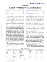
known as the global warming potential (GWP). Table 1 presents
GWPs for several common refrigerants. Table 2 compares performance of current refrigerants used in refrigeration systems.
In recent years, CO2 has once again become a refrigerant of great
interest. However, high-pressure CO2 systems (e.g., 3.4 MPa at a
saturation temperature of –1°C, or 6.7 MPa at 26.7°C) present some
challenges for containment and safety.
Advances in materials science since the 1950s enable the design
of cost-effective and efficient high-pressure carbon dioxide systems. The attraction of using CO2 in modern systems is based on its
The preparation of this chapter is assigned to TC 10.3, Refrigerant Piping.
Table 1 Refrigerant Data
Refrigerant Number
Refrigerant Group
R-22
R-134a
R-410A
HCFC
HFC
HFC blend
R-507A
HFC blend
R-717
R-744
Ammonia
Carbon dioxide
Source: ANSI/ASHRAE Standard 34.
Chemical Formula
CHClF2
CF3CH2F
HFC-32 (50%)
HFC-125 (50%)
HFC-125 (50%)
HFC-143a (50%)
NH3
CO2
Safety Group
GWP at 100 Years
–40.8
–26.1
–52.3
A1
A1
A1/A1
1700
1300
2000
–47.1
A1
3900
–33.3
–78.4
B2
A1
0
1
Note: –56.6°C and coincident pressure of 517.8 kPa (absolute) is triple point for CO2.
3.1
Copyright © 2010, ASHRAE
Temperature at
101.3 kPa, °C
This file is licensed to Abdual Hadi Nema (). License Date: 6/1/2010
3.2
2010 ASHRAE Handbook—Refrigeration (SI)
Table 2 Comparative Refrigerant Performance per
Kilowatt of Refrigeration
Fig. 1
CO2 Expansion-Phase Changes
EvaporaConNet RefrigSpecific
Refrigtor
denser
erating
Refrigerant Volume of
erant Pressure, Pressure,
Effect,
Circulated, Suction Gas,
Number
MPa
MPa
kJ/kg
kg/s
m3/kg
R-22
R-134a
R-410A
R-507A
R-717
R-744
0.3
0.16
0.48
0.38
0.24
2.25
1.19
0.77
1.87
1.46
1.16
7.18
162.2
147.6
167.6
110.0
1100.9
133.0
1.7 × 10⁻³
1.9 × 10⁻³
1.7 × 10⁻³
2.6 × 10⁻³
0.26 × 10⁻³
1.1 × 10⁻³
2.7 × 10⁻³
4.2 × 10⁻³
1.9 × 10⁻³
1.8 × 10⁻³
17.6 × 10⁻³
0.58 × 10⁻³
Licensed for single user. © 2010 ASHRAE, Inc.
Source: Adapted from Table 9 in Chapter 29 of the 2009 ASHRAE Handbook—Fundamentals. Conditions are –15°C and 30°C.
attractive thermophysical properties: low viscosity, high thermal
conductivity, and high vapor density. These result in good heat
transfer in evaporators, condensers, and gas coolers, allowing
selection of smaller equipment compared to CFCs and HFCs. Carbon dioxide is unique as a refrigerant because it is being considered
for applications spanning the HVAC&R market, ranging from
freezers to heat pumps, and from domestic units up to large-scale
industrial plants.
CO2 has been proposed for use as the primary refrigerant in
mobile air conditioners, domestic appliances, supermarket display
cases, and vending machines. CO2 heat pump water heaters are
already commercially available in a many countries. In these applications, transcritical operation (i.e., rejection of heat above the critical point) is beneficial because it allows good temperature glide
matching between the water and supercritical CO2, which benefits
the coefficient of performance (COP). Large industrial systems use
CO2 as the low-temperature-stage refrigerant in cascade systems,
typically with ammonia or R-507A as high-temperature-stage
refrigerants. Medium-sized commercial systems also use CO2 as the
low-temperature-stage refrigerant in cascade system with HFCs or
hydrocarbons as high-temperature-stage refrigerants.
A distinguishing characteristic of CO2 is its phase change properties. CO2 is commercially marketed in solid form as well as in liquid and gas cylinders. In solid form it is commonly called dry ice,
and is used in a variety of ways including as a cooling agent and as
a novelty or stage prop.
Solid CO2 sublimates to gas at –78.5°C at atmospheric pressure.
The latent heat is 571 kJ/kg. Gaseous CO2 is sold as a propellant
and is available in high-pressure cartridges in capacities from 4 g to
2.3 m3.
Liquid CO2 is dispensed and stored in large pressurized vessels
that are often fitted with an independent refrigeration system to control storage vessel pressure. Manufacturing facilities use it in both
liquid and gas phase, depending on the process or application.
Bigger quantities of CO2 (e.g., to replenish large storage tanks)
can be transported by pressurized railway containers and specialized road transport tanker trucks.
CO2 is considered a very-low-cost refrigerant at just a fraction of
the price of other common refrigerants in use today. Comparing
environmental concerns, safety issues, and cost differentials, CO2
has a positive future in mechanical refrigeration systems, serving as
both a primary and secondary refrigerant.
In considering CO2 as primary or secondary refrigerant, these
matter-phase state conditions of solid, liquid, and vapor should be
thoroughly understood. Of particular importance are the triple point
and critical point, which are illustrated in Figures 1 and 2.
The point of equilibrium where all three states coexist that is
known as the triple point. The second important pressure and temperature point of recognition is the critical point where liquid and
vapor change state. CO2 critical temperature is 31°C; this is considered to be low compared to all commonly used refrigerants.
Fig. 1 CO2 Expansion-Phase Changes
(Adapted from Vestergaard and Robinson 2003)
Fig. 2
CO2 Phase Diagram
Fig. 2 CO2 Phase Diagram
(Adapted from Vestergaard and Robinson 2003)
APPLICATIONS
Transcritical CO2 Refrigeration
In a transcritical refrigeration cycle, CO2 is the sole refrigerant.
Typical operating pressures are much higher than traditional HFC
and ammonia operating pressures. As the name suggests, the heat
source and heat sink temperatures straddle the critical temperature.
Development on modern transcritical systems started in the early
1990s with a focus on mobile air-conditioning systems. However,
early marine systems clearly were capable of transcritical operation
in warm weather, according to their operating manuals. For example, marine engineers sailing through the Suez Canal in the 1920s
reported that they had to throttle the “liquid” outlet from the condenser to achieve better efficiency if the sea water was too warm.
They did not call this transcritical operation and could not explain
why it was necessary, but their observation was correct.
The technology suggested for mobile air conditioning was also
adopted in the late 1990s for heat pumps, particularly air-source
heat pumps for domestic water heating. In Japan, researchers and
manufacturers have designed a full line of water-heating-system
equipment, from small residential units to large industrial applications, all incorporating transcritical CO2 heat pump technology. A
wide variety of such units was produced, with many different compressor types, including reciprocating, rotary piston, and scroll.
Current commercial production of pure transcritical systems is
primarily in small-scale or retail applications such as soft drink vending machines, mobile air conditioning, heat pumps, domestic appliances, and supermarket display freezers. Commercial and industrial
systems at this time tend to use CO2 as secondary refrigerant in a
This file is licensed to Abdual Hadi Nema (). License Date: 6/1/2010
Carbon Dioxide Refrigeration Systems
two-phase cascade system in conjunction with more traditional primary refrigerants such as ammonia or an HFC.
In a transcritical cycle, the compressor raises the operating pressure above the critical pressure and heat is rejected to atmosphere by
cooling the discharge gas without condensation. When the cooled
gas passes through an expansion device, it turns to a mixture of liquid and gas. If the compressor discharge pressure is raised, the
enthalpy achieved at a given cold gas temperature is reduced, so
there is an optimum operating point balancing the additional energy
input required to deliver the higher discharge pressure against the
additional cooling effect achieved through reduced enthalpy. Several optimizing algorithms have been developed to maximize efficiency by measuring saturated suction pressure and gas cooler
outlet temperature and regulating the refrigerant flow to maintain an
optimum discharge pressure. Achieving as low a temperature at the
gas cooler outlet as possible is key to good efficiency, suggesting
that there is a need for evaporatively cooled gas coolers, although
none are currently on the market. Other devices, such as expanders,
have been developed to achieve the same effect by reducing the
enthalpy during the expansion process and using the recovered work
in the compressor to augment the electrical input.
Licensed for single user. © 2010 ASHRAE, Inc.
CO2 Cascade System
The cascade system consists of two independent refrigeration
systems that share a common cascade heat exchanger. The CO2 lowtemperature refrigerant condenser serves as the high-temperature
refrigerant evaporator; this thermally connects the two refrigeration
circuits. System size influences the design of the cascade heat
exchanger: large industrial refrigeration system may use a shelland-tube vessel, plate-and-frame heat exchanger, or plate-and-shell
type, whereas commercial systems are more likely to use brazedplate, coaxial, and tube-in-tube cascade heat exchangers. In chilling
systems, the liquid CO2 is pumped from the receiver vessel below
the cascade heat exchanger to the heat load. In low-temperature
applications, the high-pressure CO2 liquid is expanded to a lower
pressure and a compressor is used to bring the suction gas back up
to the condensing pressure.
Using a cascade system allows a reduced high-temperature
refrigerant charge. This can be important in industrial applications
to minimize the amount of ammonia on site, or in commercial systems to reduce HFC refrigerant losses.
CO2 cascade systems are configured for pumped liquid recirculation, direct expansion, volatile secondary and combinations of
these that incorporate multiple liquid supply systems.
Low-temperature cascade refrigeration application include cold
storage facilities, plate freezers, ice machines, spiral and belt freezers, blast freezers, freeze drying, supermarkets, and many other
food and industrial product freezing systems.
Some theoretical studies (e.g., Vermeeren et al. (2006)] have suggested that cascade systems are inherently less efficient than twostage ammonia plants, but other system operators claim lower
energy bills for their new CO2 systems compared to traditional
ammonia plants. The theoretical studies are plausible because introducing an additional stage of heat transfer is bound to lower the
high-stage compressor suction. However, additional factors such as
the size of parasitic loads (e.g., oil pumps, hot gas leakage) on the
low-stage compressors, the effect of suction line losses, and the
adverse effect of oil in low-temperature ammonia plants all tend to
offset the theoretical advantage of two-stage ammonia system, and
in the aggregate the difference in energy consumption one way or
the other is likely to be small. Other factors, such as reduced ammonia charge, simplified regulatory requirements, or reduced operator
staff, are likely to be at least as significant in the decision whether to
adopt CO2 cascades for industrial systems.
In commercial installations, the greatest benefit of a CO2 cascade
is the reduction in HFC inventory, and consequent probable reduction in HFC emission. Use of a cascade also enables the operator to
3.3
Fig. 1
Fig. 3
CO2 Expansion-Phase Changes
Transcritical CO2 Refrigeration Cycle in Appliances
and Vending Machines
retain existing HFC compressor and condenser equipment when
refurbishing a facility by connecting it to a CO2 pump set and
replacing the evaporators and low-side piping. End users in Europe
and the United States suggest that CO2 cascade systems are simpler
and easier to maintain, with fewer controls requiring adjustment,
than the HFC systems that they are replacing. This indicates that
they are inherently more reliable and probably cheaper to maintain
than conventional systems. If the efficiency is equivalent, then the
cost of ownership will ultimately be cheaper. However, it is not clear
if these benefits derive from the higher level of engineering input
required to introduce the new technology, or whether they can be
maintained in the long term.
SYSTEM DESIGN
Transcritical CO2 Systems
Recent advances in system component design have made it possible to operate in previously unattainable pressure ranges. The
development of hermetic and semihermetic multistage CO2 compressors provided the economical ability to design air-cooled transcritical systems that are efficient, reliable, and cost effective.
Today, transcritical systems are commercially available in sizes
from the smallest appliances to entire supermarket systems. Figures
3 and 4 shows examples of simple transcritical systems. Heat rejection to atmosphere is by cooling the supercritical CO2 gas without
phase change. For maximum efficiency, the gas cooler must be able
to operate as a condenser in colder weather, and the control system
must be able to switch from gas cooler operation (where outflow
from the air-cooled heat exchanger is restricted) to condenser operation (where the restriction is removed, as in a conventional system). Compared to a typical direct HFC system, energy usage can be
reduced by 5% in colder climates such as northern Europe, but may
increase by 5% in warmer climates such as southern Europe or the
United States. In a heat pump or a refrigeration system with heat
recovery, this dual control is not necessary because the system operates transcritically at all times.
CO2/HFC Cascade Systems
Cascade refrigeration systems in commercial applications generally use HFCs, or occasionally HCs, as the primary refrigerant.
Supermarkets have adopted cascade technology for operational and
economic reasons (the primary refrigerant charge can be reduced by
as much as 75%). Liquid CO2 is pumped to low-temperature display
This file is licensed to Abdual Hadi Nema (). License Date: 6/1/2010
3.4
Fig. 2 CO2 Heat Pump for Ambient Heat to Hot Water
2010 ASHRAE Handbook—Refrigeration (SI)
Fig. 3 R-717/CO2 Cascade System with CO2 Hot-Gas
Defrosting
Licensed for single user. © 2010 ASHRAE, Inc.
Fig. 4 CO2 Heat Pump for Ambient Heat to Hot Water
cases and controlled via electronic expansion valve. The mediumtemperature display cases are supplied liquid from the same circuit
or from a dedicated pump system (Figures 5 and 6). Cascade systems in supermarkets have been designed to operate multitemperature display cases and provide heat recovery to generate hot water or
space heating (Figure 7). In general, although a pump has been
introduced, energy consumption is not significantly different from a
traditional HFC system because the suction line losses are less and
the evaporator heat transfer performance is better. This can result in
a rise of up to 5 or 6 K in the evaporating temperature, offsetting the
pump’s power consumption and the temperature differential in the
cascade heat exchanger.
Fig. 5 R-717/CO2 Cascade System with CO2 Hot-Gas
Defrosting
(Adapted from Vestergaard 2007)
Ammonia/CO2 Cascade Refrigeration System
Industrial refrigeration applications often contain large amounts
of ammonia as an operating charge. Cascade systems provide an
opportunity to reduce the ammonia charge by approximately 90%
percent compared to a conventional ammonia system of the same
capacity.
Another significant difference is the operating pressures of CO2
compared to ammonia. The typical suction pressure at –28.9°C evaporating temperature is 24.1 kPa (gage) for ammonia and 1582.4 kPa
(gage) for CO2. In most industrial cascade systems, the ammonia
charge is limited to the compressor room and the condenser flat, reducing the risk of leakage in production areas and cold storage rooms.
The cascade heat exchanger is the main component where the
two independent refrigeration systems are connected in single vessel. CO2 vapors are condensed to liquid by evaporating ammonia
liquid to vapor. This cascade heat exchanger vessel must be constructed to withstand high pressures and temperature fluctuations to
meet the requirements of both refrigerants. Also, the two refrigerants are not compatible with each other, and cross-contamination
results in blockage in the ammonia circuit and may put the system
out of commission for an extended period. The cascade heat
exchanger design must prevent internal leakage that can lead to the
two refrigerants reacting together. Figure 8 shows a simplified
ammonia cascade system; note that no oil return is shown.
System Design Pressures
The system design pressure for a CO2 cascade system cannot be
determined in the traditional way, because the design temperatures
are typically above the critical point. The system designer must
therefore select suitable pressures for each part of the system, and
ensure that the system is adequately protected against excess
pressure in abnormal circumstances (e.g., off-cycle, downtime,
power loss).
For example, for a typical refrigerated warehouse or freezer cascade system, the following pressures are appropriate:
CO2 Side
• System design working pressure (saturated suction temperature):
3.5 MPa (gage) (0.6°C)
• Relief valve settings: 3.4 MPa (gage)
• System emergency relief setting: 3.1 MPa (gage) (–3°C)
• CO2 discharge pressure setting: 2.2 MPa (gage) (–15°C)
Where the system uses hot-gas defrost, the part of the circuit
exposed to the high-pressure gas should be rated for 5.2 MPa or
higher.
Ammonia Side
• System design working pressure (saturated suction temperature):
2.1 MPa (gage) (53°C)
• Relief valve settings: 2.1 MPa (gage)
• Ammonia suction pressure setting: 108 kPa (gage) (–18°C)
• Ammonia discharge pressure setting: 1.1 MPa (gage) (32°C)
• Temperature difference on the cascade condenser: (2.8 K)
On the CO2 side, the low-side temperature and coincident pressure must be considered. The triple point for CO2 is –56.6°C). At
lower pressure, liquid turns to a solid; thus, the low-side criteria of
feasible applications are –56.6°C at a coincidental saturated suction
pressure of 414 kPa (gage). Therefore, the system must be dualstamped for 3.5 MPa (gage) and –56.6°C at 462 kPa (gage). To
achieve suitable material properties, stainless steel pipe may be
appropriate.
This file is licensed to Abdual Hadi Nema (). License Date: 6/1/2010
Carbon Dioxide Refrigeration Systems
3.5
Fig. 4 CO2 Cascade System with Two Temperature Levels
where
C
D
L
f
=
=
=
=
capacity required, kg/s of air
diameter of vessel, m
length of vessel, m
refrigerant-specific constant (0.5 for ammonia, 1.0 for CO2)
Some special considerations are necessary for liquid feed valve
assemblies to facilitate maintenance. Depending on the configuration, it may not be feasible to drain the liquid out of a valve assembly
before maintenance is needed. Liquid CO2 in the valve assembly
cannot be vented directly to atmosphere because it will turn to dry
ice immediately. Between any two valves that can trap liquid, a liquid drain valve should be installed on one side and a gas-pressuring
valve on the other. This facilitates pressurizing the valve train with
gas, pushing the liquid out without it changing phase inside the pipe.
CO2 Monitoring
Licensed for single user. © 2010 ASHRAE, Inc.
CO2 is heavier than air, but the two gases mix well; it does not
take much air movement to prevent CO2 from stratifying. The most
practical place to measure CO2 concentrations is about 1.2 m above
the floor (i.e., the breathing zone for most people). Where CO2
might leak into a stairwell, pit, or other confined space, an additional detector should be located in the space to warn personnel in
the event of a high concentration.
Water in CO2 Systems
Fig. 6 CO2 Cascade System with Two Temperature Levels
(Adapted from Vestergaard 2007)
Valves
Valves in CO2 systems are generally similar to those in ammonia
plants, but must be suitably rated for high pressure. Where equipment cannot operate at the required pressure differences, alternative
types may be used (e.g., replacing solenoid valves with electrically
driven ball valves).
Expanding saturated CO2 vapor can solidify, depending on operating pressure, so the relief valve should be located outside with no
downstream piping. If necessary, there should be a high-pressure
pipe from the vessel to the relief valve. This pipe should be sized to
ensure a suitably low pressure drop during full-flow operation.
The other very important consideration with the relief system is
its discharge location. The relief header must be located so that, if
there is a release, the discharge does not fall and collect in an area
where it may cause an asphyxiation hazard (e.g., in a courtyard, or
near the inlet of a rooftop makeup air unit).
CO2 relief valves are more likely to lift in abnormal circumstances than those used in ammonia or HFC systems, where the
valve will only lift in the event of a fire or a hydraulic lock. Therefore, care should be taken when specifying relief valves for CO2 to
ensure that the valve can reseat to prevent loss of the total refrigeration charge. A pressure-regulating valve (e.g., an actuated ball
valve) may be installed in parallel with the safety relief valve to
allow controlled venting of the vapor at a set pressure slightly lower
than the relief valve setting.
For sizing relief valves, use the following equation:
C = f DL
(1)
CO2, like HFCs, is very sensitive to any moisture within the system. Air must be evacuated before charging the refrigerant at initial
start-up, to remove atmospheric moisture. Maintenance staff must
use caution when adding oil that may contain moisture. Investigations of valve problems in some CO2 installations revealed that
many problems are caused by water freezing in the system; welldesigned and well-maintained CO2 systems charged with dry CO2
and filter-driers run trouble free (Bellstedt et al. 2002).
Figure 9 shows the water solubility in the vapor phase of different refrigerants. The acceptable level of water in CO2 systems is
much lower than with other common refrigerants. Figure 10 shows
the solubility of water in both liquid and vapor CO2 as function of
temperature. (Note that solubility in the liquid phase is much
higher.) Below these levels, water remains dissolved in the refrigerant and does not harm the system. If water is allowed to exceed the
maximum solubility limit in a CO2 system, problems may occur,
especially if the temperature is below 0°C. In this case, the water
freezes, and ice crystals may block control valves, solenoid valves,
filters, and other equipment.
If the water concentration in a CO2 system exceeds the saturation
limit, it creates carbonic acid, which can cause equipment failures
and possibly internal pipe corrosion. Filter-driers should be located
at all main liquid feed locations.
Because the entire CO2 system is at positive pressure during all
operating conditions, the most likely time for moisture penetration
is during charging. The appropriate specification for water content
depends on the size of the system and its intended operating temperature. Chilling systems are more tolerant of water than freezers,
and industrial systems with large liquid receivers are likely to be
more tolerant than small direct-expansion (DX) circuits. It is imperative that the CO2 is specified with a suitable water content. Refrigerant grade, with a content less than 5 ppm, is suitable for small
commercial systems; larger plant may use cryogenic grade, with a
content less than 20 ppm. The content should be certified by the vendor and tested on site before installing in the system. On small systems, it may also be appropriate to charge through a filter-drier.
SYSTEM SAFETY
Safety is an important factor in the design of every refrigeration
system, and is one of the main reasons why carbon dioxide is
gaining acceptance as a refrigerant of the future. CO2 is a natural
This file is licensed to Abdual Hadi Nema (). License Date: 6/1/2010
3.6
Licensed for single user. © 2010 ASHRAE, Inc.
Fig. 5
2010 ASHRAE Handbook—Refrigeration (SI)
Dual-Temperature Supermarket System: R-404 and CO2 with Cascade Condenser
Fig. 7 Dual-Temperature Supermarket System: R-404A and CO2 with Cascade Condenser
refrigerant and considered environmentally safe. As a refrigerant, it
is not without potential risks, but they are substantially smaller than
those of other refrigerants. It is a slightly toxic, odorless, colorless
gas with a slightly pungent, acid taste. Carbon dioxide is a small but
important constituent of air. CO2 will not burn or support combustion. An atmosphere containing of more than 10% CO2 will extinguish an open flame.
Mechanical failure in refrigeration equipment and piping can
course a rapid increase in concentration levels of CO2. When
inhaled at elevated concentrations, carbon dioxide may produce
mild narcotic effects, stimulation of the respiratory centre, and
asphyxiation, depending on concentration present.
In the United States, the Occupational Safety and Health Administration (OSHA) limits the permissible exposure limit (PEL) time
weighted average (TWA) concentration that must not be exceed during any 8 h per day, 40 h per week, to 5000 ppm. The OSHA shortterm exposure limit (STEL), a 15 min TWA exposure that should
not be exceeded, is 30 000 ppm. In other countries (e.g., the United
Kingdom), the STEL is lower, at 15 000 ppm.
At atmospheric pressure, carbon dioxide is a solid, which sublimes to vapor at –56.6°C. All parts of a charged CO2 refrigerating
system are above atmospheric pressure. Do not attempt to break piping joints or to remove valves or components without first ensuring
that the relevant parts of the system have been relieved of pressure.
When reducing pressure or transferring liquid carbon dioxide,
care is necessary to guard against blockages caused by solid carbon
dioxide, which forms at pressures below 517 kPa. If a blockage
occurs, it must be treated with caution. No attempt should be made
to accelerate the release of pressure by heating the blocked component.
In a room where people are present and the CO2 concentration
could exceed the refrigerant concentration limit of 0.9 kg/10 m3 in
the event of a leak, proper detection and ventilation are required.
When detectors sense a dangerous level of CO2 in a room, the alarm
system must be designed to make sure all people in the room are
evacuated and no one is allowed to re-enter until concentration levels return to acceptable ranges. Protective clothing, including gloves
and eyewear, should be standard in locations that contain CO2
equipment or controls, or where service work is done.
PIPING
Carbon Dioxide Piping Materials
When selecting piping material for CO2 refrigeration systems,
the operating pressure and temperature requirements must be understood. Suitable piping materials may include copper, carbon steel,
stainless steel, and aluminum.
Many transcritical systems standardize on brazed air-conditioning and refrigeration (ACR) copper piping for the low-pressure side
of the system, because of its availability. For pressures above 4.1
MPa, the annealing effect of brazing can weaken copper pipe, so
pipework should be welded steel. Alternatively, cold-formed
mechanical permanent joints can be used with copper pipe if the
pipe and fittings are suitably pressure rated. Small-diameter copper
tubing meets the requirement pressure ratings. The allowable internal pressure for copper tubing in service is based on a formula used
in ASME Standard B31 and ASTM Standard 280:
2St m
p = ----------------------------D – 0.08t m
(2)
where
p = allowable pressure
S = allowable stress [i.e., allowable design strength for continuous
long-term service, from ASME (2007)]
tm = wall thickness
D = outside diameter
Carbon Steel Piping for CO2
Low-temperature seamless carbon steel pipe (ASTM Standard
A333) Grade 6 is suited for conditions within refrigeration systems.
Alternatively a number of common stainless steel alloys provide
adequate low temperature properties.
This file is licensed to Abdual Hadi Nema (). License Date: 6/1/2010
Carbon Dioxide Refrigeration Systems
3.7
Licensed for single user. © 2010 ASHRAE, Inc.
Fig. 6 Dual-Temperature Ammonia Cascade System
Fig. 8 Dual-Temperature Ammonia (R-717) Cascade System
Fig. 7
Water Solubility in Various Refrigerants
Fig. 9 Water Solubility in Various Refrigerants
(Adapted from Vestergaard 2007)
Stainless steel, aluminum, and carbon steel piping require qualified welders for the piping installation.
Pipe Sizing
For the same pressure drop, CO2 has a corresponding temperature penalty 5 to 10 times smaller than ammonia and R-134a have
Fig. 8 Water Solubility in CO2
Fig. 10 Water Solubility in CO2
(Adapted from Vestergaard 2007)
(Figure 11). For a large system with an inherently large pressure
drop, the temperature penalty with CO2 is substantially less than the
same pressure drop using another refrigerant.
Because of CO2’s physical properties (particularly density), the
vapor side of the system is much smaller than in a typical ammonia
system, but the liquid side is similar or even larger because CO2’s
This file is licensed to Abdual Hadi Nema (). License Date: 6/1/2010
3.8
2010 ASHRAE Handbook—Refrigeration (SI)
three remaining units of liquid return to the vessel as two-phase
flow. The vessel then separates the two-phase flow, collecting the
liquid and allowing the dry gas to exit to the compressors. The high
gas density of CO2 means that liquid takes up a greater proportion
of the wet suction volume than with ammonia, so there is a significant advantage in reducing the circulating rate. Typically 2:1 can be
used for a cold store, whereas 4:1 would be preferred in this application for ammonia.
Design of a recirculator vessel must consider liquid flow rates.
When sizing pump flow rates, the pump manufacturer’s recommendations for liquid velocity should generally be followed:
Fig. 9 Pressure drop for various refrigerants
• NH3 and most hydrocarbons (HCs): <1.0 m/s
• CO2, HCFCs, and HFCs: 0.75 m/s
Fig. 11 Pressure Drop for Various Refrigerants
lower latent heat requires more mass flow (see Table 3). The primary
method of sizing CO2 pipe is to define the allowable temperature loss
Table 3
Pipe Size Comparison Between NH3 and CO2
Licensed for single user. © 2010 ASHRAE, Inc.
Description
CO2 at
–40°C
NH3 at
–40°C
Latent heat, kJ/kg
321.36
1386.83
4.34
2.69
Density of liquid, m3/kg
Density of vapor, m3/kg
0.04
1.55
Mass flow rate for 70 kW refrigeration effect, kg/s
0.22
0.05
0.95
0.14
Liquid volumetric flow rate, m3/s
Vapor volumetric flow rate, m3/s
8.4 × 10⁻³ 78.6 × 10⁻³
Liquid pipe sizes, mm (assumes 3:1 recirculation
40NB
25NB
rate)
Vapor pipe sizes, mm
65NB
100NB
that the system can handle, convert that to pressure loss, then size the
system so that the total pressure drop is less than or equal to the
allowable pressure drop.
HEAT EXCHANGERS AND VESSELS
CO2 operates at much higher pressures than most refrigerants for
any given operating temperature. If a vessel contained liquid CO2
and the pressure were lost through a refrigerant leak, the CO2 would
continue to refrigerate while the pressure reduced to atmospheric.
As the pressure dropped to 518 kPa, the liquid would change to a
solid and vapor at –56.6°C. (Conversely, as the pressure rises, the
solid turns back to liquid.) The CO2 would continue to cool down to
–78°C at atmospheric conditions. For a vessel, the typical design is
to be able to handle temperatures down to –56.6°C at 518 kPa. Normal operation of pumps and valves is not affected by this phase
change in the long term, although the plant obviously cannot operate when full of solid. The main hazard associated with this behavior is the effect of low temperature on the vessel materials.
Gravity Liquid Separator
This vessel is designed to separate the liquid out of two-phase
flow to protect the compressor from liquid entrainment. They can be
in either a vertical or horizontal configuration. The vessel can be
designed in accordance with Chapter 4, but using a factor of 0.03 for
CO2 compared with 0.06 for ammonia.
Recirculator
This vessel is a gravity liquid separator, but it also contains a
managed level of liquid, which is pumped out to the evaporators at
a specific flow rate. The circulating rate is the mass ratio of liquid
pumped to amount of vaporized liquid. A 4:1 circulating rate means
four units of liquid are pumped out and one unit evaporates. The
Recirculator drop legs should be sized for a liquid velocity of less
than 0.075 to 0.10 m/s to allow vapor bubbles to rise and to prevent
oil entrainment in the pump suction line.
CO2’s liquid density is typically higher than the oil’s density; typical approximate values are 1200 kg/m3 for liquid CO2, 900 kg/m3
for oil, and 660 kg/m3 for liquid ammonia. Thus, unlike in ammonia
systems, oil that reaches the low side of a CO2 system tends to float
on the surface of the refrigerant. This makes oil recovery from the
recirculator more difficult, but, conversely, it means that oil is more
likely to remain in the high-pressure receiver, if one is fitted, floating
atop the liquid there.
Cascade Heat Exchanger
The CO2 compressor discharge in a low-temperature system or
the wet return in a pumped liquid chill system is piped to the cascade
heat exchanger, where the heat of rejection from the low stage is
removed by the high-stage system and condenses the CO2 discharge
gas to high-pressure liquid. The high-stage system absorbs the heat
of rejection from the low stage by evaporating the high-stage refrigerant.
There are several configuration of the cascade heat exchanger.
Industrial applications use conventional shell-and-tube, welded
plate-in-shell, and plate-and-frame heat exchangers. To reduce the
risk of cross-contamination, some projects use shell-and-tube heat
exchangers with double tube sheets, which are significantly more
expensive than single-tube sheet heat exchangers. In commercial
applications system capacity influences design criteria; equipment
options include brazed-plate, tube-in-tube, coaxial, shell-and-tube,
and plate and frame heat exchangers.
COMPRESSORS FOR CO2
REFRIGERATION SYSTEMS
Designing and manufacturing an efficient, reliable CO2 compressor represented a challenge that required extensive research to
satisfy the complex criteria dictated by operating pressures that far
exceed those found in conventional refrigeration compressors.
Transcritical Compressors for Commercial
Refrigeration
In transcritical CO2 systems, the design working pressure exceed
10 MPa (gage) in air-cooled applications. Construction techniques
and materials must withstand the pressure ranges that are essential
for transcritical CO2 compression. With traditional reciprocating
compressors, one challenge is to provide enough surface on the
wrist pin and big-end bearings to carry the load created by the high
differential pressure. Development of new compressor types
included two-stage rotary hermetic units, redesigned scroll and
reciprocating compressors, and a hybrid piston configuration where
an eccentric lobe drives a roller piston rather than a connecting rod.
These are often fitted with inverter-type dc motors designed to
change speeds from 1800 to 6000 rpm to satisfy part-load and efficiency requirements.
This file is licensed to Abdual Hadi Nema (). License Date: 6/1/2010
Carbon Dioxide Refrigeration Systems
3.9
Fig. 10 CO2 Transcritical Compressor Configuration Chart
Licensed for single user. © 2010 ASHRAE, Inc.
Fig. 12 CO2 Transcritical Compressor Configuration Chart
Compressor manufacturers generally use one of three conventional enclosure or housing styles (Figure 12): hermetic (used by
appliance and heat pump manufacturers), modified semihermetic
(used in compressors for supermarkets), or open-style belt-driven
compressors (used in transport and industrial refrigeration compressors).
As different segments of the refrigeration industry developed
CO2 equipment, each individual segment gravitated to designs that
evolved from their standard compressor arrangements. For example, in the automotive industry, the typical R-134a vehicle air-conditioning compressor modified to operate with CO2 has a more
robust exterior enclosure, a more durable shaft seal arrangement,
and stronger bearing configurations with reduced component clearances. However, the basic multiroller piston/swash plate, beltdriven compressor design remains fundamentally similar.
High-pressure screw compressors are also in development for
commercial applications, in both single- and two-stage internally
compound versions.
Compressors for Industrial Applications
There are two primary types of compressors used for industrial
applications: rotary screw and reciprocating. These compressors
have been designed primarily for cascade systems with CO2 as the
low-temperature refrigerant. Modification requirements for the CO2
cascade system compressors are less demanding because the temperature and pressure thresholds are lower than those of transcritical
compressors for commercial applications.
Depending on the operating parameters, the reciprocating compressor crankcase pressure may be considerably higher when using
CO2. Therefore, standard gray cast iron material may not meet the
design specification criteria. Construction material strength may be
increased by selecting ductile cast iron for compressor casings in
both single- and two-stage versions. Internal moving components
and bearing surfaces may also require new materials that tolerate the
elevated pressures.
Typical screw compressors may also be modified to ductile cast
iron casings in lieu of gray iron for higher design working pressures.
Shorter rotor lengths may be required to reduce deflection at the
higher operating pressures of CO2 applications, and the discharge
port may be enlarged to improve the compressor efficiency with the
dense gas.
The same advantages and disadvantages apply to these two types
of compressors as with ammonia and most HFCs, with a few clarifications. Because CO2 has a greater density than ammonia and
HFCs commonly used in industrial applications, the displacement
volume needed in the CO2 compressor is comparatively less than
that required for other refrigerants. For example, at –40°C saturated
suction temperature, a CO2 refrigeration system’s displacement
requirement is approximately eight times less than ammonia for the
same refrigeration effect. Therefore, the compressors are approximately eight times smaller for the CO2 system.
High-pressure screw compressors are also in development for
industrial applications, in both single- and two-stage internally
compound versions.
LUBRICANTS
There are several very suitable oils for use with CO2. Some oils
are fully miscible with the refrigerant and some are nonmiscible.
Each application requires a lubricant that meets specific temperature and miscibility characteristics. Lubricants include mineral oils,
alkyl benzene, polyalphaolefin (PAO), polyol ester (POE), and
polyalkyl glycol (PAG).
The development of a transcritical CO2 system requires specialty
lubricants because of the high pressure and thus higher bearing
loads. Antiwear properties and extreme pressures create a challenge
to provide a lubricant that achieves compressor longevity. Cascade
systems can use more traditional oils, and it may be possible to
reduce the risk of error by using the same lubricant in both sides of
the cascade.
Currently, ASHRAE and other organizations are performing
research with a variety of lubricants in different viscosity ranges to
assess the oil structure and thermodynamic behavior in CO2 systems (Bobbo et al. 2006; Rohatgi 2010; Tsiji et al. 2004). POE and
PAG oils are widely accepted in today’s CO2 systems; however, the
dynamics of the refrigerant and oil mixture for different pressures,
temperatures and buoyancy levels have yet to be established for all
conditions. Chapter 12 covers details on CO2 lubricants.
In CO2, insoluble oils are less dense than the liquid refrigerant.
Providing a series of sampling points connected to an oil pot provides
a means of finding the level of stratification and removing the oil.
For fully soluble oils, a small side stream of liquid refrigerant is
passed through an oil rectifier, which can recover this oil from the
low temperature side and deliver it back to the compressor, as in
some R-22 applications. The oil rectifier is principally a shell-andtube heat exchanger, which uses the high-pressure liquid to heat the
refrigerant/oil sample. The tube side is connected to the bottom of
the surge drum, so that low-pressure liquid is boiled off, and the
remaining oil is directed to the suction line.
The oil rectifier liquid supply should be at least 1% of the plant
capacity. The oil rectifier does not affect the plant efficiency because
the liquid used subcools the remaining plant liquid. Typically, the oil
rectifier is sized to maintain a concentration of 1% oil in the CO2
charge. Oil carryover from a reciprocating compressor with a standard oil separator is typically 10 to 20 ppm for CO2 operation.
This file is licensed to Abdual Hadi Nema (). License Date: 6/1/2010
3.10
2010 ASHRAE Handbook—Refrigeration (SI)
Licensed for single user. © 2010 ASHRAE, Inc.
EVAPORATORS
Evaporator designs for CO2 cascade or transcritical systems are
similar to those for other refrigerants. If the design pressure is low
enough, then standard air coolers/plate freezers for either ammonia
or HFCs can be used for CO2 and yield similar capacity at the same
temperatures. The heat transfer coefficients in CO2 evaporators are
typically double those found in R-134a systems, and about half of
those in ammonia systems. However, the pressure/temperature
characteristic of CO2 offers the possibility to increase the mass flux
in the evaporator to achieve higher rates of heat transfer without suffering from excessive saturated temperature drop. Air units specifically designed for CO2 with small stainless steel tube circuiting
(16, 13, or 9.5 mm) and aluminum fins, increase heat transfer performance in industrial and commercial applications. Plate freezer
design can be optimized with significantly smaller channels, and
thus thinner plates, than are traditionally used for ammonia, enabling up to 8% more product to be fitted into a given frame size.
Most CO2 evaporators control the liquid supply to coil distributor
with liquid overfeed or electronic controlled direct expansion
valves, development in flow control technology is being studied in
many research facilities to provide optimal performance and superheat conditions. Developments in microchannel evaporator technology for smaller capacity systems have also provided excellent heat
transfer capabilities.
In low-temperature application where surface frosting accumulates and coil defrosting is required, hot-gas defrost air units require
the design pressure to be in excess of 5.2 MPa (gage). If this is not
feasible, then electric defrost can be used. Provided the coil is
pumped down and vented during defrost, pressure will not rise
above the normal suction condition during an electric defrost.
For plate freezers, the low pressure drop (expressed as saturated
suction temperature) is significantly less for CO2 than for any other
refrigerant. This is because of (1) the pressure/temperature characteristic and (2) the lower overfeed ratio that can be used. Freezing
times in plate freezers are dramatically reduced (up to one-third of
the cycle time required with ammonia). Defrost in plate freezers
must be by hot gas.
Copper pipe and aluminum fin evaporators have been successfully used in commercial and supermarket applications for several
years with CO2 in both cascade and transcritical installations. Compared to HFC evaporators, these new units are typically smaller,
with reduced tube diameter and fewer, longer circuits to take full
advantage of the pressure/temperature characteristic. Conversion
from R-22 has been achieved in some installations by utilizing the
original electric defrost evaporators, rated for 2.6 MPa (gage). CO2
has also been deployed in cooling coils for vacuum freeze dryers
and in ice rinks floors. There are generally no problems with oil
fouling, provided an oil with a sufficiently low pour point is used.
DEFROST
Perhaps the greatest diversity in the system design is in the type
of defrost used, because of the greater degree of technical innovation required to achieve a satisfactory result in coil defrosting. There
are significant differences in the installation costs of the different
systems, and they also result in different operating costs. For systems operating below 0°C where the evaporator is cooling air, efficient and effective defrost is an essential part of the system. Some
types of freezers also require a defrost cycle to free the product at the
end of the freezing process of service. Tunnel freezers may well
require a quick, clean defrost of one of the coolers while the others
are in operation.
Electric Defrost
The majority of small carbon dioxide systems, particularly
those installed in supermarket display cases in the early 1990s and
later, used electric defrost. This technology was very familiar in the
commercial market, where it was probably the preferred method of
defrosting R-502 and R-22 systems. With electric defrost, it is
imperative that the evaporator outlet valve (suction shutoff valve) is
open during defrost so that the coil is vented to suction; otherwise,
the high temperature produced by the electric heaters could cause
the cooler to burst. It therefore also becomes important to pump out
or drain the coil before starting defrost, because otherwise the initial energy fed into the heaters only evaporates the liquid left in the
coil, and this gas imposes a false load on the compressor pack.
Exactly the same warnings apply to industrial systems, where electric defrost is becoming more common.
If electric defrost is used in a cold store with any refrigerant, then
each evaporator should be fitted with two heater control thermostats. The first acts as the defrost termination, sensing when the coil
rises to a set level and switching off the heater. The second is a safety
stat, and should be wired directly into the control circuit for the
cooler, to ensure that all power to the fans, peripheral heaters, tray
heaters, and defrost heater elements is cut off in the event of excessive temperature. One advantage of electric defrost in a carbon dioxide system is that, if the coil is vented, coil pressure will not rise
above the suction pressure during defrost. This is particularly appropriate for retrofit projects, where existing pipes and perhaps evaporators are reused on a new carbon dioxide system.
The electric system comprises rod heaters embedded in the coil
block in spaces between the tubes. The total electrical heating
capacity is 0.5 times the coil duty plus an allowance for the drip tray
heaters and fan peripheral heaters.
Hot-Gas Defrost
This is the most common form of defrost in industrial systems,
particularly on ammonia plant. The common name is rather misleading, and the method of achieving defrost is often misunderstood. The
gas does not need to be hot to melt frost, but it does need it to be at
a sufficiently high pressure that its saturation temperature is well
above 0°C. In ammonia plants, this is achieved by relieving pressure
from the evaporator through a pressure regulator, which is factory-set
at 0.5 MPa (gage), giving a condensing temperature of about 7°C.
Despite this, it is common to find hot-gas defrost systems supplied
by a plant that runs at a condensing temperature of 35°C to deliver
the required flow rate. This equates to a head pressure of 1.3 MPa
(gage), which means that there is a an 800 kPa pressure drop between
the high-pressure receiver and the evaporator. The real penalty paid
with this error in operation is that the rest of the plant is running at the
elevated pressure and consuming far more energy than necessary.
With carbon dioxide compressors supplying the gas, there is no possibility of the same mistake: the typical compressor used in this
application is likely to be rated for 5 MPa (gage) allowable pressure,
and so runs at about 4.5 MPa (gage), which gives a condensing temperature in the coil of about 10°C. Numerous applications of this
type have shown that this is perfectly adequate to achieve a quick and
clean defrost (Nielsen and Lund 2003). In some arrangements, the
defrost compressor suction draws from the main carbon dioxide
compressor discharge, and acts as a heat pump. This has the benefit
of reducing load on the high side of the cascade, and offers significant energy savings. These can be increased if the defrost machine is
connected to the suction of the carbon dioxide loop, because it then
provides cooling in place of one of the main carbon dioxide compressors. A concern about this system is that it runs the compressor to its
limits, but only intermittently, so there are many starts and stops over
a high differential. The maintenance requirement on these machines
is higher than normal because of this harsh operating regime.
Reverse-Cycle Defrost
Reverse-cycle defrost is a special form of hot-gas defrost in which
heat is applied by condensing gas in the evaporator, but it is delivered
by diverting all compressor discharge gas to the evaporator and supplying high-pressure liquid to the system condenser, thus producing
This file is licensed to Abdual Hadi Nema (). License Date: 6/1/2010
Carbon Dioxide Refrigeration Systems
reverse flow in part of the circuit and operating the plant as a heat
pump. Gas diversion is typically done with a single valve (e.g., a
four-port ball valve). Reverse-cycle defrost is most appropriate in
transcritical circuits, and is particularly suitable for use in lowpressure receiver systems as described by Pearson (1996).
High Pressure Liquid Defrost
Licensed for single user. © 2010 ASHRAE, Inc.
An alternative way of providing gas for defrosting is to pressurize liquid and then evaporate it, using waste heat from the high-pressure side of the cascade. This has the advantage that it does not
require a high-pressure compressor, but uses a small liquid pump
instead. The liquid evaporator stack is quite expensive, because it
comprises an evaporator, liquid separator, and superheater, but
ongoing development is helping to make this part of the system
more economical. This type of system has been used very successfully in cold and chill storage (Pearson and Cable 2003) and in a
plate freezer plant (Blackhurst 2002). It is particularly well suited to
the latter application because the defrost load is part of the product
freezing cycle and is large and frequent. The heat for evaporation is
provided by condensing ammonia on the other side of a plate-andshell heat exchanger; in cold and chill applications, where defrosts
are much less frequent, the heat is supplied by glycol from the oilcooling circuit on the ammonia stage.
Water Defrost
Water defrost can be used, although this is usually limited to coils
within spiral and belt freezers that require a cleandown cycle (e.g.,
IQF freezers, freeze-drying plants).
INSTALLATION, START-UP, AND
COMMISSIONING
It is imperative to take every feasible precaution to prevent moisture from entering the system. Because CO2 operates at positive
pressure about the triple point, the most likely times for contamination are at start-up and during system charging.
When a system is complete and ready for pressure testing, a series
of cleansing processes should be used to ensure a totally dry system.
First, the system should be pulled into a deep vacuum (98 kPa) and
held with a vacuum pump running for a minimum of 1 hour for each
30 m3 of system to remove moisture. All low spots that are not insulated should be inspected for evidence of moisture (ice, condensation) and the vacuum process continued until any moisture is gone.
Hold the vacuum for 24 h. Break the vacuum with dry nitrogen to
bring the system up to design working pressure for 24 h. Soap-test
every joint and flange. Repair as needed and repeat. When confident
of the system integrity, pull the system back into a vacuum (98 kPa)
and hold for 24 h to purge all nitrogen and other contaminates.
Break the vacuum with CO2 gas. On a large system, this can be
very cumbersome, but trying to charge a system with liquid can
cause severe problems. First, as the liquid enters the vacuum, it
immediately solidifies and clogs the charging system. Secondly, the
shock of such low temperatures can cause the metal of the system to
crack. Only charge a CO2 system with gas until the system is up to
a minimum pressure of 1.4 MPa (gage). At this pressure, the corresponding temperature is about –30°C, which will not shock the
metal of the system when liquid is introduced.
Daily maintenance and service of an ammonia/CO2 cascade system is very similar to a conventional ammonia system, but is typically quicker and easier. When servicing equipment, remember the
following points:
• Do not trap liquid between two isolation valves. Trapped liquid
CO2 expands very quickly when heated and can easily reach rupture pressure. CO2 gas can rise above design pressure when
trapped, so do not isolate gas where heat can be added to the
equipment and superheat the gas.
3.11
• Pumpdown of a piece of equipment (e.g., an evaporator) follows
typical procedure. The liquid isolation valve is closed, and the
evaporator fans are run to evaporate all of the remaining liquid.
When all of the liquid is out, the fans are turned off, the suction is
closed, and the unit is isolated with gas on it at suction pressure.
It is recommended to install service valves in the strainers of all
liquid solenoids and at each piece of equipment to enable the technician to vent the remaining pressure to atmosphere in a controlled fashion. When service is complete, the unit must be pulled
back to a deep vacuum to remove all moisture. Break the vacuum
by opening up the evaporator to suction and allow the unit to fill
with CO2 gas and pressurize the coil. Then open the liquid. If the
liquid is opened before the unit is up to 1.4 MPa (gage), the liquid
will turn solid and clog the liquid supply line.
• Evacuation is particularly critical in CO2 systems because, unlike
ammonia, CO2 does not tolerate much water.
• It is not necessary to blow refrigerant out into a water container
(as with ammonia) or to pump refrigerant out with recovery units
(as with HFCs). After isolating a component, the CO2 contained
within can simply be released into the atmosphere. In addition,
when the component is opened for service, no extra time is
required waiting for the refrigerant smell to dissipate. The main
caution with releasing CO2 indoors is to ensure the room is well
ventilated and monitored by a CO2 detector to make sure the concentration of CO2 does not get too high.
• For systems that use soluble oils, an oil rectifier system distills the
oil out and sends it back to the compressors automatically.
• With systems that use insoluble oils, sampling ports must be
added to the recirculator to drain off the oil, similar to an R-22
system. Liquid CO2 is significantly more dense than lubricants,
so the oil tends to float on the surface of the liquid in the receiver.
• At initial start-up and during service, air and moisture may potentially contaminate a CO2 system. However, during normal operation, the CO2 side of the system always operates at a positive
pressure in all areas of the plant, thereby preventing air and moisture from entering the system. Air purgers are not needed, but filter-driers are.
Making sure the CO2 does not get contaminated is very important. Samples of the system CO2 should be tested regularly to confirm the absence of water or other contaminants.
REFERENCES
ASHRAE. 2007. Designation and safety classification of refrigerants.
ANSI/ASHRAE Standard 34-2007.
ASME. 2001. Refrigeration piping and heat transfer components. Standard
B31.5. American Society of Mechanical Engineers, New York.
ASME. 2007. International boiler and pressure vessel code, section 1:
Power boilers. American Society of Mechanical Engineers, New York.
ASTM. 2008. Standard specification for seamless copper tube for air conditioning and refrigeration field service. Standard B280-08. American
Society for Testing and Materials, West Conshohocken, PA.
ASTM. 2005. Specification for seamless and welded steel pipe for low-temperature service. Standard A333/A333M-05. American Society for Testing and Materials, West Conshohocken, PA.
Bellstedt, M., F. Elefsen, and S.S. Jensen. 2002. Application of CO2 refrigerant in industrial cold storage refrigeration plant. AIRAH Journal: Ecolibrium 1(5):25-30.
Blackhurst, D.R. 2002. CO2 vs. NH3: A comparison of two systems. Proceedings of the Institute of Refrigeration, vol. 99.:29-39.
Bobbo, S., M. Scattolini, R. Camporese, and L. Fedele. 2006. Solubility of
CO2 in some commercial POE oil. Proceedings of 7th IIR Conference.
IIAR. 2010. The carbon dioxide industrial refrigeration handbook. International Institute of Ammonia Refrigeration, Alexandria, VA.
Nielsen, P.S. and T. Lund 2003. Introducing a new ammonia/CO2 cascade
concept for large fishing vessels. Proceedings of IIAR Ammonia Refrigeration Conference, Albuquerque, NM, pp. 359-396.
Pearson, A.B. and P.J. Cable. 2003. A distribution warehouse with carbon
dioxide as the refrigerant. 21st IIR International Congress of Refrigeration, Washington, D.C.
This file is licensed to Abdual Hadi Nema (). License Date: 6/1/2010
3.12
2010 ASHRAE Handbook—Refrigeration (SI)
Pearson, S.F. 2001. Ammonia low pressure receivers. Air Conditioning and
Refrigeration Journal (January-March). Available at rae.
in/journals/2001jan/article05.html.
Rohatgi, N.D. 2010. Stability of candidate lubricants for CO2 refrigeration.
ASHRAE Research Project RP-1409, ongoing.
Tsiji, T., S. Tanaka, T. Hiaki, and R. Sato. 2004. Measurements of the bubble
point pressure for CO2 and lubricants. Fluid Phase Equilibria 219:87-92.
Vermeeren, R.J.F., A. Jurgens, and S.M. Van Der Sluis. 2006. Quick freezing
with carbon dioxide to achieve higher product quality. IIR Conference
Proceedings.
Vestergaard, N.P. 2007. CO2 refrigerant for industrial refrigeration. Danfoss Refrigeration and Air Conditioning Division. Available at http://
www.danfoss.com.
Vestergaard, N,P. and M. Robinson. 2003. CO2 in refrigeration applications.
Air Conditioning, Heating, and Refrigeration News (October).
Licensed for single user. © 2010 ASHRAE, Inc.
BIBLIOGRAPHY
Bondinus, W.S. 1999. The rise and fall of carbon dioxide systems. ASHRAE
Journal 41.(4):37-42.
Broderdorf, W. and D. Giza. 1993. CO2 subcooled refrigeration system. Proceedings of IIAR Ammonia Refrigeration Conference.
Broesby-Olsen, F. 1998. International Symposium on HCFC Alternative
Refrigerants.
Christensen, O. 2006. System design for industrial ammonia/CO2 cascade
installations. Proceedings of IIAR Ammonia Refrigeration Conference.
Gillies, A.M. 2004. Design considerations when using carbon dioxide in
industrial refrigeration systems. Proceedings of IIR 6th Gustav Lorentzen Conference, Glasgow.
Handschuh, R. 2008. Design criteria for CO2 evaporators. In Natural refrigerants—Sustainable ozone- and climate-friendly alternatives to HCFCs,
pp. 273-282. V. Hasse, L. Ederberg, and D. Colbourne, eds. GTZ
Proklima, Eschborn, Germany. Available from />themen/umwelt-infrastruktur/23898.htm.
IOR. 2009. Safety code of practice for carbon dioxide as a refrigerant. Institute of Refrigeration, Carshalton, U.K.
Lorentzen, G. 1994. The use of natural refrigerants, a complete solution to the
CFC/HCFC predicament. IIR Conference Proceedings: New Applications
of Natural Working Fluids in Refrigeration and Air Conditioning.
Lorentzen, G. 1990. Trans-critical vapour compression cycle device. Patent
WO/07683.
Miller, H. 1985. Halls of Dartford 1785-1985. Ebury Press, UK.
Pearson, A. 2000. The use of CO2/NH3 cascade systems for low temperature
food refrigeration. IIAR 22nd Annual Meeting, Nashville, pp. 43-58.
Pearson, A. 2005. Evaporator performance in carbon dioxide systems. Proceedings of IIAR Ammonia Refrigeration Conference.
Pearson, A. 2006. Defrost options for carbon dioxide systems. Proceedings
of IIAR Ammonia Refrigeration Conference.
Pearson, S.F. 2004. Rational design for suction pipes to liquid refrigerant
pumps. Proceedings of IIR 6th Gustav Lorentzen Conference, Glasgow.
Pettersen, J. 1999. CO2 as a primary refrigerant. Presented at Institute of
Refrigeration Centenary Conference, London.
Renz, H. 1999. Semi-hermetic reciprocating and screw compressors for carbon dioxide cascade systems. 20th International Congress of Refrigeration, IIR/IIF, Syndey. Available at />files/hutestechnika_letoltesek/av_9801_gb.pdf.
Saikawa, M. 2007. Development and progress of CO2 heat pump water
heater “Eco-Cute” in Japan.
Vestergaard, N.P. 2004. Getting to grips with carbon dioxide. RAC (Refrigeration and Air Conditioning).
Vestergaard, N.P. 2004. CO2 in subcritical refrigeration systems. Presented
at IIAR Conference, Orlando.
Woolrich, W.R. 1967. The men who created cold: A history of refrigeration.
Exposition Press, New York.
ACKNOWLEDGMENT
ASHRAE and International Institute of Ammonia Refrigeration
(IIAR) joint members contributed both to this chapter and to IIAR’s
Carbon Dioxide Industrial Refrigeration Handbook (IIAR 2010),
material from which was used in this chapter’s development.
Related Commercial Resources