SI r10 ch02
Bạn đang xem bản rút gọn của tài liệu. Xem và tải ngay bản đầy đủ của tài liệu tại đây (2.11 MB, 28 trang )
This file is licensed to Abdual Hadi Nema (). License Date: 6/1/2010
Related Commercial Resources
CHAPTER 2
Licensed for single user. © 2010 ASHRAE, Inc.
AMMONIA REFRIGERATION SYSTEMS
System Selection......................................................................... 2.1
Equipment .................................................................................. 2.2
Controls...................................................................................... 2.7
Piping......................................................................................... 2.8
Reciprocating Compressors ..................................................... 2.11
Rotary Vane, Low-Stage
Compressors......................................................................... 2.12
Screw Compressors ..................................................................
Condenser and Receiver Piping...............................................
Evaporative Condensers ..........................................................
Evaporator Piping....................................................................
Multistage Systems ...................................................................
Liquid Recirculation Systems ...................................................
Safety Considerations...............................................................
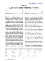
C
reduces its enthalpy, resulting in a higher net refrigerating effect.
Economizing is beneficial because the vapor generated during subcooling is injected into the compressor partway through its compression cycle and must be compressed only from the economizer
port pressure (which is higher than suction pressure) to the discharge pressure. This produces additional refrigerating capacity
with less increase in unit energy input. Economizing is most beneficial at high pressure ratios. Under most conditions, economizing
can provide operating efficiencies that approach that of two-stage
systems, but with much less complexity and simpler maintenance.
Economized systems for variable loads should be selected carefully. At approximately 75% capacity, most screw compressors
revert to single-stage performance as the slide valve moves such that
the economizer port is open to the compressor suction area.
A flash economizer, which is somewhat more efficient, may
often be used instead of the shell-and-coil economizer (Figure 1).
However, ammonia liquid delivery pressure is reduced to economizer pressure. Additionally, the liquid is saturated at the lower
pressure and subject to flashing with any pressure drop unless
another means of subcooling is incorporated.
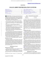
USTOM-ENGINEERED ammonia (R-717) refrigeration systems often have design conditions that span a wide range of
evaporating and condensing temperatures. Examples are (1) a food
freezing plant operating from 10 to –45°C; (2) a candy storage
requiring 15°C db with precise humidity control; (3) a beef chill
room at –2 to –1°C with high humidity; (4) a distribution warehouse
requiring multiple temperatures for storing ice cream, frozen food,
meat, and produce and for docks; and (5) a chemical process requiring multiple temperatures ranging from 15 to –50°C. Ammonia is
the refrigerant of choice for many industrial refrigeration systems.
The figures in this chapter are for illustrative purposes only, and
may not show all the required elements (e.g., valves). For safety
and minimum design criteria for ammonia systems, refer to
ASHRAE Standard 15, IIAR Bulletin 109, IIAR Standard 2, and
applicable state and local codes.
See Chapter 24 for information on refrigeration load calculations.
Ammonia Refrigerant for HVAC Systems
There is renewed interest in using ammonia for HVAC systems
has received renewed interest, in part because of the scheduled phaseout and increasing costs of chlorofluorocarbon (CFC) and hydrochlorofluorocarbon (HCFC) refrigerants. Ammonia secondary systems
that circulate chilled water or another secondary refrigerant are a viable alternative to halocarbon systems, although ammonia is inappropriate for direct refrigeration systems (ammonia in the air unit coils)
for HVAC applications. Ammonia packaged chilling units are available for HVAC applications. As with the installation of any air-conditioning unit, all applicable codes, standards, and insurance
requirements must be followed.
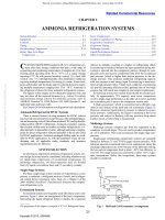
Multistage Systems
Multistage systems compress gas from the evaporator to the
condenser in several stages. They are used to produce temperatures
of –25°C and below. This is not economical with single-stage compression.
Single-stage reciprocating compression systems are generally
limited to between 35 and 70 kPa (gage) suction pressure. With
lubricant-injected economized rotary screw compressors, where the
discharge temperatures are lower because of the lubricant cooling,
the low-suction temperature limit is about –40°C, but efficiency is
very low. Two-stage systems are used down to about –60°C evaporator temperatures. Below this temperature, three-stage systems
should be considered.
SYSTEM SELECTION
In selecting an engineered ammonia refrigeration system, several design decisions must be considered, including whether to use
(1) single-stage compression, (2) economized compression, (3)
multistage compression, (4) direct-expansion feed, (5) flooded
feed, (6) liquid recirculation feed, and (7) secondary coolants.
Fig. 1 Shell-and-Coil Economizer Arrangement
Single-Stage Systems
The basic single-stage system consists of evaporator(s), a compressor, a condenser, a refrigerant receiver (if used), and a refrigerant control device (expansion valve, float, etc.). Chapter 2 of the
2009 ASHRAE Handbook—Fundamentals discusses the compression refrigeration cycle.
Economized Systems
Economized systems are frequently used with rotary screw compressors. Figure 1 shows an arrangement of the basic components.
Subcooling the liquid refrigerant before it reaches the evaporator
Fig. 1 Shell-and-Coil Economizer Arrangement
The preparation of this chapter is assigned to TC 10.3, Refrigerant Piping.
2.1
Copyright © 2010, ASHRAE
2.13
2.15
2.17
2.18
2.21
2.22
2.27
This file is licensed to Abdual Hadi Nema (). License Date: 6/1/2010
2.2
2010 ASHRAE Handbook—Refrigeration (SI)
Fig. 2 Two-Stage System with High- and
Low-Temperature Loads
Fig. 2 Two-Stage System with High- and
Low-Temperature Loads
Licensed for single user. © 2010 ASHRAE, Inc.
Two-stage systems consist of one or more compressors that operate at low suction pressure and discharge at intermediate pressure
and have one or more compressors that operate at intermediate pressure and discharge to the condenser (Figure 2).
Where either single- or two-stage compression systems can be
used, two-stage systems require less power and have lower operating costs, but they can have a higher initial equipment cost.
EQUIPMENT
Compressors
Compressors available for single- and multistage applications include the following:
• Reciprocating
Single-stage (low-stage or high-stage)
Internally compounded
• Rotary vane
• Rotary screw (low-stage or high-stage, with or without
economizing)
The reciprocating compressor is the most common compressor
used in small, 75 kW or less, single-stage or multistage systems. The
screw compressor is the predominant compressor above 75 kW, in
both single- and multistage systems. Various combinations of compressors may be used in multistage systems. Rotary vane and screw
compressors are frequently used for the low-pressure stage, where
large volumes of gas must be moved. The high-pressure stage may be
a reciprocating or screw compressor.
When selecting a compressor, consider the following:
• System size and capacity requirements.
• Location, such as indoor or outdoor installation at ground level or
on the roof.
• Equipment noise.
• Part- or full-load operation.
• Winter and summer operation.
• Pulldown time required to reduce the temperature to desired conditions for either initial or normal operation. The temperature
must be pulled down frequently for some applications for a process load, whereas a large cold-storage warehouse may require
pulldown only once in its lifetime.
Lubricant Cooling. When a reciprocating compressor requires
lubricant cooling, an external heat exchanger using a refrigerant or
secondary cooling is usually added. Screw compressor lubricant
cooling is covered in detail in the section on Screw Compressors.
Compressor Drives. The correct electric motor size(s) for a
multistage system is determined by pulldown load. When the final
low-stage operating level is –75°C, the pulldown load can be three
times the operating load. Positive-displacement reciprocating compressor motors are usually selected for about 150% of operating
power requirements for 100% load. The compressor’s unloading
mechanism can be used to prevent motor overload. Electric motors
should not be overloaded, even when a service factor is indicated.
For screw compressor applications, motors should be sized by adding 10% to the operating power. Screw compressors have built-in
unloading mechanisms to prevent motor overload. The motor
should not be oversized, because an oversized motor has a lower
power factor and lower efficiency at design and reduced loads.
Steam turbines or gasoline, natural gas, propane, or diesel internal combustion engines are used when electricity is unavailable, or
if the selected energy source is cheaper. Sometimes they are used in
combination with electricity to reduce peak demands. The power
output of a given engine size can vary as much as 15% depending on
the fuel selected.
Steam turbine drives for refrigerant compressors are usually limited to very large installations where steam is already available at
moderate to high pressure. In all cases, torsional analysis is required
to determine what coupling must be used to dampen out any pulsations transmitted from the compressor. For optimum efficiency, a
turbine should operate at a high speed that must be geared down for
reciprocating and possibly screw compressors. Neither the gear
reducer nor the turbine can tolerate a pulsating backlash from the
driven end, so torsional analysis and special couplings are essential.
Advantages of turbines include variable speed for capacity control and low operating and maintenance costs. Disadvantages
include higher initial costs and possible high noise levels. The turbine must be started manually to bring the turbine housing up to
temperature slowly and to prevent excess condensate from entering
the turbine.
The standard power rating of an engine is the absolute maximum,
not the recommended power available for continuous use. Also,
torque characteristics of internal combustion engines and electric
motors differ greatly. The proper engine selection is at 75% of its
maximum power rating. For longer life, the full-load speed should
be at least 10% below maximum engine speed.
Internal combustion engines, in some cases, can reduce operating
cost below that for electric motors. Disadvantages include (1) higher
initial cost of the engine, (2) additional safety and starting controls,
(3) higher noise levels, (4) larger space requirements, (5) air pollution, (6) requirement for heat dissipation, (7) higher maintenance
costs, and (8) higher levels of vibration than with electric motors. A
torsional analysis must be made to determine the proper coupling if
engine drives are chosen.
Condensers
Condensers should be selected on the basis of total heat rejection
at maximum load. Often, the heat rejected at the start of pulldown is
several times the amount rejected at normal, low-temperature operating conditions. Some means, such as compressor unloading, can
be used to limit the maximum amount of heat rejected during pulldown. If the condenser is not sized for pulldown conditions, and
compressor capacity cannot be limited during this period, condensing pressure might increase enough to shut down the system.
Evaporators
Several types of evaporators are used in ammonia refrigeration
systems. Fan-coil, direct-expansion evaporators can be used, but they
are not generally recommended unless the suction temperature is
–18°C or higher. This is due in part to the relative inefficiency of
the direct-expansion coil, but more importantly, the low mass flow
rate of ammonia is difficult to feed uniformly as a liquid to the coil.
Instead, ammonia fan-coil units designed for recirculation (overfeed)
systems are preferred. Typically, in this type of system, high-pressure
ammonia from the system high stage flashes into a large vessel at the
evaporator pressure, from which it is pumped to the evaporators at an
overfeed rate of 2.5 to 1 to 4 to 1. This type of system is standard and
very efficient. See Chapter 4 for more details.
This file is licensed to Abdual Hadi Nema (). License Date: 6/1/2010
Licensed for single user. © 2010 ASHRAE, Inc.
Ammonia Refrigeration Systems
Flooded shell-and-tube evaporators are often used in ammonia
systems in which indirect or secondary cooling fluids such as water,
brine, or glycol must be cooled.
Some problems that can become more acute at low temperatures
include changes in lubricant transport properties, loss of capacity
caused by static pressure from the depth of the pool of liquid refrigerant in the evaporator, deterioration of refrigerant boiling heat
transfer coefficients caused by lubricant logging, and higher specific volumes for the vapor.
The effect of pressure losses in the evaporator and suction piping
is more acute in low-temperature systems because of the large
change in saturation temperatures and specific volume in relation to
pressure changes at these conditions. Systems that operate near or
below zero gage pressure are particularly affected by pressure loss.
The depth of the pool of boiling refrigerant in a flooded evaporator exerts a liquid pressure on the lower part of the heat transfer
surface. Therefore, the saturation temperature at this surface is
higher than that in the suction line, which is not affected by the liquid pressure. This temperature gradient must be considered when
designing the evaporator.
Spray shell-and-tube evaporators, though not commonly used,
offer certain advantages. In this design, the evaporator’s liquid depth
penalty can be eliminated because the pool of liquid is below the
heat transfer surface. A refrigerant pump sprays liquid over the
surface. Pump energy is an additional heat load to the system, and
more refrigerant must be used to provide the net positive suction
pressure required by the pump. The pump is also an additional item
that must be maintained. This evaporator design also reduces the
refrigerant charge requirement compared to a flooded design (see
Chapter 4).
Vessels
High-Pressure Receivers. Industrial systems generally incorporate a central high-pressure refrigerant receiver, which serves as the
primary refrigerant storage location in the system. It handles refrigerant volume variations between the condenser and the system’s low
side during operation and pumpdowns for repairs or defrost. Ideally,
the receiver should be large enough to hold the entire system charge,
but this is not generally economical. The system should be analyzed
to determine the optimum receiver size. Receivers are commonly
equalized to the condenser inlet and operate at the same pressure as
the condenser. In some systems, the receiver is operated at a pressure between the condensing pressure and the highest suction pressure to allow for variations in condensing pressure without affecting
the system’s feed pressure. This type is commonly referred to as a
controlled-pressure receiver (CPR). Liquid from the condenser is
metered through a high-side control as it is condensed. CPR pressure is maintained with a back-pressure regulator vented to an intermediate pressure point. Winter or low-load operating conditions
may require a downstream pressure regulator to maintain a minimum pressure.
If additional receiver capacity is needed for normal operation,
use extreme caution in the design. Designers usually remove the inadequate receiver and replace it with a larger one rather than install
an additional receiver in parallel. This procedure is best because
even slight differences in piping pressure or temperature can cause
the refrigerant to migrate to one receiver and not to the other.
Smaller auxiliary receivers can be incorporated to serve as
sources of high-pressure liquid for compressor injection or thermosiphon, lubricant cooling, high-temperature evaporators, and so forth.
Intercoolers (Gas and Liquid). An intercooler (subcooler/
desuperheater) is the intermediate vessel between the high and low
stages in a multistage system. One purpose is to cool discharge gas
of the low-stage compressor to prevent overheating the high-stage
compressor. This can be done by bubbling discharge gas from the
low-stage compressor through a bath of liquid refrigerant or by
mixing liquid normally entering the intermediate vessel with the
2.3
discharge gas as it enters above the liquid level. Heat removed from
the discharge gas is absorbed by evaporating part of the liquid and
eventually passes through the high-stage compressor to the condenser. Disbursing the discharge gas below a level of liquid refrigerant separates out any lubricant carryover from the low-stage
compressor. If liquid in the intercooler is to be used for other purposes, such as liquid makeup or feed to the low stage, periodic lubricant removal is imperative.
Another purpose of the intercooler is to lower the liquid temperature used in the low stage of a two-stage system. Lowering refrigerant temperature in the intercooler with high-stage compressors
increases the refrigeration effect and reduces the low-stage compressor’s required displacement, thus reducing its operating cost.
Intercoolers for two-stage compression systems can be shelland-coil or flash. Figure 3 depicts a shell-and-coil intercooler incorporating an internal pipe coil for subcooling high-pressure liquid
before it is fed to the low stage of the system. Typically, the coil subcools liquid to within 6 K of the intermediate temperature.
Vertical shell-and-coil intercoolers perform well in many applications using ammonia refrigerant systems. Horizontal designs are
possible but usually not practical. The vessel must be sized properly
to separate liquid from vapor that is returning to the high-stage compressor. The superheated gas inlet pipe should extend below the liquid level and have perforations or slots to distribute the gas evenly
in small bubbles. Adding a perforated baffle across the area of the
vessel slightly below the liquid level protects against violent surging. A float switch that shuts down the high-stage compressor when
the liquid level gets too high should always be used. A means of
maintaining a liquid level for the subcooling coil and low-stage
compressor desuperheating is necessary if no high-stage evaporator
overfeed liquid is present. Electronic level controls (see Figure 10)
can simplify the use of multiple float switches and float valves to
maintain the various levels required.
The flash intercooler is similar in design to the shell-and-coil
intercooler, except for the coil. The high-pressure liquid is flashcooled to the intermediate temperature. Use caution in selecting a
flash intercooler because all the high-pressure liquid is flashed to
intermediate pressure. Though colder than that of the shell-and-coil
intercooler, liquid in the flash intercooler is not subcooled and is
susceptible to flashing from system pressure drop.Two-phase liquid
feed to control valves may cause premature failure because of the
wire-drawing effect of the liquid/vapor mixture.
Fig. 3 Intercooler
Fig. 3
Intercooler
This file is licensed to Abdual Hadi Nema (). License Date: 6/1/2010
2.4
Licensed for single user. © 2010 ASHRAE, Inc.
Fig. 4
2010 ASHRAE Handbook—Refrigeration (SI)
Arrangement for Compound System with Vertical Intercooler and Suction Trap
Fig. 4 Arrangement for Compound System with Vertical Intercooler and Suction Trap
Figure 4 shows a vertical shell-and-coil intercooler as piped into
the system. The liquid level is maintained in the intercooler by a
float that controls the solenoid valve feeding liquid into the shell
side of the intercooler. Gas from the first-stage compressor enters
the lower section of the intercooler, is distributed by a perforated
plate, and is then cooled to the saturation temperature corresponding to intermediate pressure.
When sizing any intercooler, the designer must consider (1) lowstage compressor capacity; (2) vapor desuperheating, liquid makeup requirements for the subcooling coil load, or vapor cooling load
associated with the flash intercooler; and (3) any high-stage side
loading. The volume required for normal liquid levels, liquid surging from high-stage evaporators, feed valve malfunctions, and liquid/vapor must also be analyzed.
Necessary accessories are the liquid level control device and
high-level float switch. Though not absolutely necessary, an auxiliary oil pot should also be considered.
Suction Accumulator. A suction accumulator (also known as a
knockout drum, suction trap, pump receiver, recirculator, etc.) prevents liquid from entering the suction of the compressor, whether on
the high or low stage of the system. Both vertical and horizontal vessels can be incorporated. Baffling and mist eliminator pads can
enhance liquid separation.
Suction accumulators, especially those not intentionally maintaining a level of liquid, should have a way to remove any build-up of
ammonia liquid. Gas boil-out coils or electric heating elements are
costly and inefficient.
Although it is one of the more common and simplest means of
liquid removal, a liquid boil-out coil (Figure 5) has some drawbacks. Generally, warm liquid flowing through the coil is the source
of liquid being boiled off. Liquid transfer pumps, gas-powered
transfer systems, or basic pressure differentials are a more positive
means of removing the liquid (Figures 6 and 7).
Accessories should include a high-level float switch for compressor protection along with additional pump or transfer system
controls.
Vertical Suction Trap and Pump. Figure 8 shows the piping of
a vertical suction trap that uses a high-pressure ammonia pump to
transfer liquid from the system’s low-pressure side to the highpressure receiver. Float switches piped on a float column on the side
Fig. 5 Suction Accumulator with Warm Liquid Coil
Fig. 5
Suction Accumulator with Warm Liquid Coil
of the trap can start and stop the liquid ammonia pump, sound an
alarm in case of excess liquid, and sometimes stop the compressors.
When the liquid level in the suction trap reaches the setting of
the middle float switch, the liquid ammonia pump starts and reduces the liquid level to the setting of the lower float switch, which
stops the liquid ammonia pump. A check valve in the discharge line
of the ammonia pump prevents gas and liquid from flowing backward through the pump when it is not in operation. Depending on
the type of check valve used, some installations have two valves in
a series as an extra precaution against pump backspin.
Compressor controls adequately designed for starting, stopping,
and capacity reduction result in minimal agitation, which helps separate vapor and liquid in the suction trap. Increasing compressor
This file is licensed to Abdual Hadi Nema (). License Date: 6/1/2010
Ammonia Refrigeration Systems
Fig. 6 Equalized Pressure Pump Transfer System
2.5
Fig. 8 Piping for Vertical Suction Trap and High-Head Pump
Fig. 6 Equalized Pressure Pump Transfer System
Licensed for single user. © 2010 ASHRAE, Inc.
Fig. 7 Gravity Transfer System
Fig. 8 Piping for Vertical Suction Trap and
High-Pressure Pump
Fig. 9 Gage Glass Assembly for Ammonia
Fig. 7
Gravity Transfer System
capacity slowly and in small increments reduces liquid boiling in the
trap, which is caused by the refrigeration load of cooling the refrigerant and metal mass of the trap. If another compressor is started
when plant suction pressure increases, it should be brought on line
slowly to prevent a sudden pressure change in the suction trap.
A high level of liquid in a suction trap should activate an alarm or
stop the compressors. Although eliminating the cause is the most
effective way to reduce a high level of excess surging liquid, a more
immediate solution is to stop part of the compression system and
raise plant suction pressure slightly. Continuing high levels indicate
insufficient pump capacity or suction trap volume.
Liquid Level Indicators. Liquid level can be indicated by visual
indicators, electronic sensors, or a combination of the two. Visual indicators include individual circular reflex level indicators (bull’s-eyes)
mounted on a pipe column or stand-alone linear reflex glass assemblies
(Figure 9). For operation at temperatures below the frost point, transparent plastic frost shields covering the reflex surfaces are necessary. Also,
the pipe column must be insulated, especially when control devices are
attached to prevent false level readings caused by heat influx.
Electronic level sensors can continuously monitor liquid level.
Digital or graphic displays of liquid level can be locally or remotely
monitored (Figure 10).
Level indicators should have adequate isolation valves. Hightemperature glass tube indicators should incorporate stop check or
excess-flow valves for isolation and safety.
Fig. 9
Fig. 10
Gage Glass Assembly for Ammonia
Electronic Liquid Level Control
Fig. 10
Electronic Liquid Level Control
This file is licensed to Abdual Hadi Nema (). License Date: 6/1/2010
2.6
2010 ASHRAE Handbook—Refrigeration (SI)
Licensed for single user. © 2010 ASHRAE, Inc.
Fig. 11 Purge Unit and Piping for Noncondensable Gas
Fig. 11 Noncondensable Gas and Water Removal Unit
Purge Units. A noncondensable gas separator (purge unit) is useful in most plants, especially when suction pressure is below atmospheric pressure. Purge units on ammonia systems are piped to carry
noncondensables (air) from the receiver and condenser to the purger,
as shown in Figure 11. The suction from the coil should be taken to
one of the low-temperature suction mains. Ammonia vapor and noncondensable gas are drawn into the purger, and the ammonia condenses on the cold surface, sorting out the noncondensables. When
the drum fills with air and other noncondensables, a level control in
the purger opens and allows them to be released. Depending on operating conditions, a trace of ammonia may remain in the noncondensable gases. The noncondensable gases are diverted to a water bottle
(generally with running water) to diffuse the pungent odor of the
ammonia. Ammonia systems, which are inherently large, have
multiple points where noncondensables can collect. Purge units that
can automatically sequence through the various points and remove
noncondensables are available.
Ammonia’s affinity for water poses another system efficiency
concern. The presence of water increases the refrigerant temperature
above the saturated pressure. The increased temperature requires
lower operating pressures to maintain the same refrigerant temperature. Unlike noncondensable gases, which collect in the system’s
high side and result in higher condensing pressures, the presence of
water is less obvious. Water collects in the liquid phase and forms an
aqua/ammonia solution. Short of a complete system charge removal,
distillers (temporary or permanent) can be incorporated. Automatic
noncondensable and water removal units can provide continual
monitoring of the system impurities (Figure 11).
This file is licensed to Abdual Hadi Nema (). License Date: 6/1/2010
Licensed for single user. © 2010 ASHRAE, Inc.
Ammonia Refrigeration Systems
2.7
Lubricant Management
Liquid Feed Control
Most lubricants are immiscible in ammonia and separate out of
the liquid easily when flow velocity is low or when temperatures are
lowered. Normally, lubricants can be easily drained from the system. However, if the temperature is very low and the lubricant is not
properly selected, it becomes a gummy mass that prevents refrigerant controls from functioning, blocks flow passages, and fouls
heat transfer surfaces. Proper lubricant selection and management is
often the key to a properly functioning system.
In two-stage systems, proper design usually calls for lubricant
separators on both the high- and low-stage compressors. A properly
designed coalescing separator can remove almost all the lubricant
that is in droplet or aerosol form. Lubricant that reaches its saturation
vapor pressure and becomes a vapor cannot be removed by a separator. Separators that can cool the discharge gas condense much of the
vapor for consequent separation. Using lubricants that have very low
vapor pressures below 80°C can minimize carryover to 2 or 3 mg/kg.
Take care, however, to ensure that refrigerant is not condensed and
fed back into the compressor or separator, where it can lower lubricity and cause compressor damage.
In general, direct-expansion and liquid overfeed system evaporators have fewer lubricant return problems than do flooded system
evaporators because refrigerant flows continuously at good velocities to sweep lubricant from the evaporator. Low-temperature systems using hot-gas defrost can also be designed to sweep lubricant
out of the circuit each time the system defrosts. This reduces the possibility of coating the evaporator surface and hindering heat transfer.
Flooded evaporators can promote lubricant build-up in the evaporator charge because they may only return refrigerant vapor back
to the system. In ammonia systems, the lubricant is simply drained
from the surge drum. At low temperatures, this procedure is difficult if the lubricant selected has a pour point above the evaporator
temperature.
Lubricant Removal from Ammonia Systems. Most lubricants
are miscible with liquid ammonia only in very small proportions.
The proportion decreases with the temperature, causing lubricant to
separate. Ammonia evaporation increases the lubricant ratio, causing more lubricant to separate. Increased density causes the lubricant (saturated with ammonia at the existing pressure) to form a
separate layer below the ammonia liquid.
Unless lubricant is removed periodically or continuously from the
point where it collects, it can cover the heat transfer surface in the
evaporator, reducing performance. If gage lines or branches to level
controls are taken from low points (or lubricant is allowed to accumulate), these lines will contain lubricant. The higher lubricant density is at a lower level than the ammonia liquid. Draining lubricant
from a properly located collection point is not difficult unless the
temperature is so low that the lubricant does not flow readily. In this
case, keeping the receiver at a higher temperature may be beneficial.
Alternatively, a lubricant with a lower pour point can be selected.
Lubricant in the system is saturated with ammonia at the existing
pressure. When the pressure is reduced, ammonia vapor separates,
causing foaming.
Draining lubricant from ammonia systems requires special care.
Ammonia in lubricant foam normally starts to evaporate and produces a smell. Operators should be made aware of this. On systems
where lubricant is drained from a still, a spring-loaded drain valve,
which closes if the valve handle is released, should be installed.
Many controls available for single-stage, high-temperature systems may be used with some discretion on low-temperature systems.
If the liquid level is controlled by a low-side float valve (with the
float in the chamber where the level is controlled), low pressure and
temperature have no appreciable effect on operation. External float
chambers, however, must be thoroughly insulated to prevent heat
influx that might cause boiling and an unstable level, affecting the
float response. Equalizing lines to external float chambers, particularly the upper line, must be sized generously so that liquid can reach
the float chamber, and gas resulting from any evaporation may be
returned to the vessel without appreciable pressure loss.
The superheat-controlled (thermostatic) expansion valve is generally used in direct-expansion evaporators. This valve operates on
the difference between bulb pressure, which is responsive to suction
temperature, and pressure below the diaphragm, which is the actual
suction pressure.
The thermostatic expansion valve is designed to maintain a preset superheat in suction gas. Although the pressure-sensing part of
the system responds almost immediately to a change in conditions,
the temperature-sensing bulb must overcome thermal inertia before
its effect is felt on the power element of the valve. Thus, when compressor capacity decreases suddenly, the expansion valve may overfeed before the bulb senses the presence of liquid in the suction line
and reduces the feed. Therefore, a suction accumulator should be
installed on direct-expansion low-temperature systems with multiple expansion valves.
CONTROLS
Refrigerant flow controls are discussed in Chapter 11. The following precautions are necessary in the application of certain controls in low-temperature systems.
Controlling Load During Pulldown
System transients during pulldown can be managed by controlling compressor capacity. Proper load control reduces compressor
capacity so that energy requirements stay within the motor and condenser capacities. On larger systems using screw compressors, a
current-sensing device reads motor amperage and adjusts the capacity control device appropriately. Cylinders on reciprocating compressors can be unloaded for similar control.
Alternatively, a downstream, outlet, or crankcase pressure regulator can be installed in the suction line to throttle suction flow if the
pressure exceeds a preset limit. This regulator limits the compressor’s
suction pressure during pulldown. The disadvantage of this device is
the extra pressure drop it causes when the system is at the desired
operating conditions. To overcome some of this, the designer can use
external forces to drive the valve, causing it to be held fully open when
the pressure is below the maximum allowable. Systems using downstream pressure regulators and compressor unloading must be carefully designed so that the two controls complement each other.
Operation at Varying Loads and Temperatures
Compressor and evaporator capacity controls are similar for multiand single-stage systems. Control methods include compressor capacity control, hot-gas bypass, or evaporator pressure regulators. Low
pressure can affect control systems by significantly increasing the specific volume of the refrigerant gas and the pressure drop. A small pressure reduction can cause a large percentage capacity reduction.
System load usually cannot be reduced to near zero, because this
results in little or no flow of gas through the compressor and consequent overheating. Additionally, high pressure ratios are detrimental to the compressor if it is required to run at very low loads. If the
compressor cannot be allowed to cycle off during low load, an
acceptable alternative is a hot-gas bypass. High-pressure gas is fed
to the low-pressure side of the system through a downstream pressure regulator. The gas should be desuperheated by injecting it at a
point in the system where it is in contact with expanding liquid, such
as immediately downstream of the liquid feed to the evaporator.
Otherwise, extremely high compressor discharge temperatures can
result. The artificial load supplied by high-pressure gas can fill the
This file is licensed to Abdual Hadi Nema (). License Date: 6/1/2010
2.8
2010 ASHRAE Handbook—Refrigeration (SI)
Fig. 12 Hot-Gas Injection Evaporator for Operations
at Low Load
Tongue-and-groove or ANSI flanges should be used in ammonia
piping. Welded flanges for low-side piping can have a minimum
1 MPa design pressure rating. On systems located in high ambients,
low-side piping and vessels should be designed for 1.4 to 1.6 MPa.
The high side should be 1.7 MPa if the system uses water-cooled or
evaporative cooled condensing. Use 2.1 MPa minimum for aircooled designs.
Pipe Joints
Fig. 12 Hot-Gas Injection Evaporator for Operations
at Low Load
gap between the actual load and the lowest stable compressor operating capacity. Figure 12 shows such an arrangement.
Licensed for single user. © 2010 ASHRAE, Inc.
Electronic Control
Microprocessor- and computer-based control systems are becoming the norm for control systems on individual compressors as well as
for entire system control. Almost all screw compressors use microprocessor control systems to monitor all safety functions and operating conditions. These machines are frequently linked together with a
programmable controller or computer for sequencing multiple compressors so that they load and unload in response to system fluctuations in the most economical manner. Programmable controllers are
also used to replace multiple defrost time clocks on larger systems for
more accurate and economical defrosting. Communications and data
logging allow systems to operate at optimum conditions under transient load conditions even when operators are not in attendance.
PIPING
Local codes or ordinances governing ammonia mains should be
followed, in addition to the recommendations here.
Recommended Material
Because copper and copper-bearing materials are attacked by
ammonia, they are not used in ammonia piping systems. Steel piping, fittings, and valves of the proper pressure rating are suitable for
ammonia gas and liquid.
Ammonia piping should conform to ASME Standard B31.5,
and to IIAR Standard 2, which states the following:
1. Liquid lines 40 mm and smaller shall be not less than Schedule
80 carbon steel pipe.
2. Liquid lines 50 to 150 mm shall be not less than Schedule 40 carbon steel pipe.
3. Liquid lines 200 to 300 mm shall be not less than Schedule 20
carbon steel pipe.
4. Vapor lines 150 mm and smaller shall be not less than Schedule
40 carbon steel pipe.
5. Vapor lines 200 to 300 mm shall be not less than Schedule 20 carbon steel pipe.
6. Vapor lines 350 mm and larger shall be not less than Schedule 10
carbon steel pipe.
7. All threaded pipe shall be Schedule 80.
8. Carbon steel pipe shall be ASTM Standard A53 Grade A or B,
Type E (electric resistance welded) or Type S (seamless); or
ASTM Standard A106 (seamless), except where temperaturepressure criteria mandate a higher specification material. Standard A53 Type F is not permitted for ammonia piping.
Fittings
Couplings, elbows, and tees for threaded pipe are for a minimum
of 21 MPa design pressure and constructed of forged steel. Fittings
for welded pipe should match the type of pipe used (i.e., standard fittings for standard pipe and extra-heavy fittings for extra-heavy pipe).
Joints between lengths of pipe or between pipe and fittings can
be threaded if the pipe size is 32 mm or smaller. Pipe 40 mm or
larger should be welded. An all-welded piping system is superior.
Threaded Joints. Many sealants and compounds are available
for sealing threaded joints. The manufacturer’s instructions cover
compatibility and application method. Do not use excessive
amounts or apply on female threads because any excess can contaminate the system.
Welded Joints. Pipe should be cut and beveled before welding.
Use pipe alignment guides and provide a proper gap between pipe
ends so that a full-penetration weld is obtained. The weld should be
made by a qualified welder, using proper procedures such as the
Welding Procedure Specifications, prepared by the National Certified Pipe Welding Bureau (NCPWB).
Gasketed Joints. A compatible fiber gasket should be used with
flanges. Before tightening flange bolts to valves, controls, or flange
unions, properly align pipe and bolt holes. When flanges are used
to straighten pipe, they put stress on adjacent valves, compressors,
and controls, causing the operating mechanism to bind. To prevent
leaks, flange bolts are drawn up evenly when connecting the
flanges. Flanges at compressors and other system components must
not move or indicate stress when all bolts are loosened.
Union Joints. Steel (21 MPa) ground joint unions are used for
gage and pressure control lines with screwed valves and for joints
up to 20 mm. When tightening this type of joint, the two pipes
must be axially aligned. To be effective, the two parts of the union
must match perfectly. Ground joint unions should be avoided if at
all possible.
Pipe Location
Piping should be at least 2.3 m above the floor. Locate pipes carefully in relation to other piping and structural members, especially
when lines are to be insulated. The distance between insulated lines
should be at least three times the thickness of the insulation for screwed
fittings, and four times for flange fittings. The space between the pipe
and adjacent surfaces should be three-fourths of these amounts.
Hangers located close to the vertical risers to and from compressors keep the piping weight off the compressor. Pipe hangers should
be placed no more than 2.5 to 3 m apart and within 0.6 m of a change
in direction of the piping. Hangers should be designed to bear on the
outside of insulated lines. Sheet metal sleeves on the lower half of
the insulation are usually sufficient. Where piping penetrates a wall,
a sleeve should be installed, and where the pipe penetrating the wall
is insulated, it must be adequately sealed.
Piping to and from compressors and to other components
must provide for expansion and contraction. Sufficient flange or
union joints should be located in the piping so components can
be assembled easily during installation and also disassembled
for servicing.
Pipe Sizing
Table 1 presents practical suction line sizing data based on
0.005 K and 0.01 K differential pressure drop equivalent per metre
total equivalent length of pipe, assuming no liquid in the suction
line. For data on equivalent lengths of valves and fittings, refer to
Tables 10, 11, and 12 in Chapter 1. Table 2 lists data for sizing suction and discharge lines at 0.02 K differential pressure drop equivalent per metre equivalent length of pipe, and for sizing liquid lines
This file is licensed to Abdual Hadi Nema (). License Date: 6/1/2010
Ammonia Refrigeration Systems
2.9
Table 1 Suction Line Capacities in Kilowatts for Ammonia with Pressure Drops of 0.005 and 0.01 K/m Equivalent
Saturated Suction Temperature, °C
–50
–40
–30
Steel Nominal Line
Size, mm
t = 0.005 K/m
p = 12.1 Pa/m
t = 0.01 K/m
p = 24.2 Pa/m
t = 0.005 K/m
p = 19.2 Pa/m
t = 0.01 K/m
p = 38.4 Pa/m
t = 0.005 K/m
p = 29.1 Pa/m
t = 0.01 K/m
p = 58.2 Pa/m
10
15
20
25
32
40
50
65
80
100
125
150
200
250
300
0.19
0.37
0.80
1.55
3.27
4.97
9.74
15.67
28.08
57.95
105.71
172.28
356.67
649.99
1045.27
0.29
0.55
1.18
2.28
4.80
7.27
14.22
22.83
40.81
84.10
153.05
248.91
514.55
937.58
1504.96
0.35
0.65
1.41
2.72
5.71
8.64
16.89
27.13
48.36
99.50
181.16
294.74
609.20
1107.64
1777.96
0.51
0.97
2.08
3.97
8.32
12.57
24.50
39.27
69.99
143.84
261.22
424.51
874.62
1589.51
2550.49
0.58
1.09
2.34
4.48
9.36
14.15
27.57
44.17
78.68
161.77
293.12
476.47
981.85
1782.31
2859.98
0.85
1.60
3.41
6.51
13.58
20.49
39.82
63.77
113.30
232.26
420.83
683.18
1402.03
2545.46
4081.54
Licensed for single user. © 2010 ASHRAE, Inc.
Saturated Suction Temperature, °C
20
5
Steel Nominal Line
Size, mm
t = 0.005 K/m
p = 42.2 Pa/m
t = 0.01 K/m
p = 84.4 Pa/m
t = 0.005 K/m
p = 69.2 Pa/m
10
15
20
25
32
40
50
65
80
100
125
150
200
250
300
0.91
1.72
3.66
6.98
14.58
21.99
42.72
68.42
121.52
249.45
452.08
733.59
1506.11
2731.90
4378.87
1.33
2.50
5.31
10.10
21.04
31.73
61.51
98.23
174.28
356.87
646.25
1046.77
2149.60
3895.57
6237.23
1.66
3.11
6.61
12.58
26.17
39.40
76.29
122.06
216.15
442.76
800.19
1296.07
2662.02
4818.22
7714.93
+5
t = 0.01 K/m
p = 138.3 Pa/m
2.41
4.50
9.53
18.09
37.56
56.39
109.28
174.30
308.91
631.24
1139.74
1846.63
3784.58
6851.91
10 973.55
t = 0.005 K/m
p = 92.6 Pa/m
2.37
4.42
9.38
17.79
36.94
55.53
107.61
171.62
304.12
621.94
1124.47
1819.59
3735.65
6759.98
10 810.65
t = 0.01 K/m
p = 185.3 Pa/m
3.42
6.37
13.46
25.48
52.86
79.38
153.66
245.00
433.79
885.81
1598.31
2590.21
5303.12
9589.56
15 360.20
Note: Capacities are in kilowatts of refrigeration resulting in a line friction loss per unit equivalent pipe length (p in Pa/m), with corresponding change in saturation temperature
per unit length (t in K/m).
at 0.5 m/s. Charts prepared by Wile (1977) present pressure drops
in saturation temperature equivalents. For a complete discussion
of the basis of these line sizing charts, see Timm (1991). Table 3
presents line sizing information for pumped liquid lines, highpressure liquid lines, hot-gas defrost lines, equalizing lines, and
thermosiphon lubricant cooling ammonia lines.
Valves
Stop Valves. These valves, also commonly called shutoff or isolation valves, are generally manually operated, although motoractuated units are available. ASHRAE Standard 15 requires these
valves in the inlet and outlet lines to all condensers, compressors,
and liquid receivers. Additional valves are installed on vessels,
evaporators, and long lengths of pipe so they can be isolated in case
of leaks and to facilitate pumping out for servicing and evacuation.
Sections of liquid piping that can experience hydraulic lockup in
normal operation must be protected with a relief device (preferably
vented back into the system). Only qualified personnel should be
allowed to operate stop valves.
Installing globe-type stop valves with the valve stems horizontal
lessens the chance (1) for dirt or scale to lodge on the valve seat or
disk and cause it to leak or (2) for liquid or lubricant to pocket in the
area below the seat. Wet suction return lines (recirculation system)
should use angle valves or globe valves (with their stems horizontal)
to reduce the possibility of liquid pockets and reduce pressure drop.
Welded flanged or weld-in-line valves are desirable for all line
sizes; however, screwed valves may be used for 32 mm and smaller
lines. Ammonia globe and angle valves should have the following
features:
•
•
•
•
•
Soft seating surfaces for positive shutoff (no copper or copper alloy)
Back seating to permit repacking the valve stem while in service
Arrangement that allows packing to be tightened easily
All-steel construction (preferable)
Bolted bonnets above 25 mm, threaded bonnets for 25 mm and
smaller
Consider seal cap valves in refrigerated areas and for all ammonia piping. To keep pressure drop to a minimum, consider angle
valves (as opposed to globe valves).
Control Valves. Pressure regulators, solenoid valves, check
valves, gas-powered suction stop valves, and thermostatic expansion
valves can be flanged for easy assembly and removal. Alternative
This file is licensed to Abdual Hadi Nema (). License Date: 6/1/2010
2.10
2010 ASHRAE Handbook—Refrigeration (SI)
Table 2
Suction, Discharge Line, and Liquid Capacities in Kilowatts for Ammonia (Single- or High-Stage Applications)
Discharge Lines
t = 0.02 K/m, p = 684.0 Pa/m
Suction Lines (t = 0.02 K/m)
Licensed for single user. © 2010 ASHRAE, Inc.
Steel
Saturated Suction Temperature, °C
Nominal
Line Size,
–40
–30
–20
–5
+5
mm
p = 76.9 p = 116.3 p = 168.8 p = 276.6 p = 370.5
Saturated Suction Temp., °C
–40
–20
+5
Liquid Lines
Steel
Nominal
Line Size,
mm
Velocity =
0.5 m/s
p = 450.0
10
15
20
0.8
1.4
3.0
1.2
2.3
4.9
1.9
3.6
7.7
3.5
6.5
13.7
4.9
9.1
19.3
8.0
14.9
31.4
8.3
15.3
32.3
8.5
15.7
33.2
10
15
20
3.9
63.2
110.9
63.8
118.4
250.2
25
32
40
5.8
12.1
18.2
9.4
19.6
29.5
14.6
30.2
45.5
25.9
53.7
80.6
36.4
75.4
113.3
59.4
122.7
184.4
61.0
126.0
189.4
62.6
129.4
194.5
25
32
40
179.4
311.0
423.4
473.4
978.0
1469.4
50
65
80
35.4
56.7
101.0
57.2
91.6
162.4
88.1
140.6
249.0
155.7
248.6
439.8
218.6
348.9
616.9
355.2
565.9
1001.9
364.9
581.4
1029.3
374.7
597.0
1056.9
50
65
80
697.8
994.8
1536.3
2840.5
4524.8
8008.8
100
125
150
200
206.9
375.2
608.7
1252.3
332.6
601.8
975.6
2003.3
509.2
902.6
1491.4
3056.0
897.8
1622.0
2625.4
5382.5
1258.6
2271.4
3672.5
7530.4
2042.2
3682.1
5954.2
12 195.3
2098.2
3783.0
6117.4
12 529.7
2154.3
3884.2
6281.0
12 864.8
—
—
—
—
—
—
—
—
—
—
—
—
250
300
2271.0
3640.5
3625.9
5813.5
5539.9
8873.4
9733.7
15568.9
13619.6
21787.1
22 028.2
35 239.7
22 632.2
36 206.0
23 237.5
37 174.3
—
—
—
—
—
—
Notes:
1. Table capacities are in kilowatts of refrigeration.
4. Values are based on 30°C condensing temperature. Multiply table capacities by the following factors for other condensing temperatures:
p = pressure drop due to line friction, Pa/m
t = corresponding change in saturation temperature, K/m
2. Line capacity for other saturation temperatures t and equivalent lengths Le
Condensing
Temperature, °C
20
30
40
50
Table L
Actual t 0.55
Line capacity = Table capacity ----------------------e- -----------------------
Actual L e Table t
3. Saturation temperature t for other capacities and equivalent lengths Le
Actual L
Actual capacity 1.8
t = Table t -----------------------e -------------------------------------
Table L e Table capacity
Suction
Lines
1.04
1.00
0.96
0.91
Discharge
Lines
0.86
1.00
1.24
1.43
5. Liquid line capacities based on 5°C suction.
Table 3 Liquid Ammonia Line Capacities in Kilowatts
Nominal
Size, mm
Pumped Liquid Overfeed Ratio
3:1
4:1
5:1
High-Pressure
Liquid
at 21 kPaa
Hot-Gas
Defrosta
Equalizer
High Sideb
Thermosiphon Lubricant Cooling
Lines Gravity Flowc
Supply
Return
Vent
40
513
387
308
1544
106
791
59
35
60
50
1175
879
703
3573
176
1055
138
88
106
65
1875
1407
1125
5683
324
1759
249
155
187
80
2700
2026
1620
10 150
570
3517
385
255
323
100
4800
3600
2880
—
1154
7034
663
413
586
125
—
—
—
—
2089
—
1041
649
1062
150
—
—
—
—
3411
—
1504
938
1869
200
—
—
—
—
—
—
2600
1622
3400
Source: Wile (1977).
for hot-gas branch lines under 30 m with minimum inlet pressure of 724 kPa
(gage), defrost pressure of 483 kPa (gage), and –29°C evaporators designed for a 5.6 K
temperature differential
aRating
weld-in line valves with nonwearing body parts are available. Valves
40 mm and larger should have socket- or butt-welded companion
flanges. Smaller valves can have threaded companion flanges.
A strainer should be used in front of self-contained control valves
to protect them from pipe construction material and dirt.
Solenoid Valves. Solenoid valve stems should be upright, with
their coils protected from moisture. They should have flexible
b Line
sizes based on experience using total system evaporator kilowatts.
Frick Co. (1995). Values for line sizes above 100 mm are extrapolated.
c From
conduit connections, where allowed by codes, and an electric pilot
light wired in parallel to indicate when the coil is energized.
Solenoid valves for high-pressure liquid feed to evaporators
should have soft seats for positive shutoff. Solenoid valves for other
applications, such as in suction, hot-gas, or gravity feed lines,
should be selected for the pressure and temperature of the fluid
flowing and for the pressure drop available.
This file is licensed to Abdual Hadi Nema (). License Date: 6/1/2010
Ammonia Refrigeration Systems
Relief Valves. Safety valves must be provided in conformance
with ASHRAE Standard 15 and Section VIII, Division 1, of the
ASME Boiler and Pressure Vessel Code. For ammonia systems,
IIAR Bulletin 109 also addresses the subject of safety valves.
Dual relief valve arrangements allow testing of the relief valves
(Figure 13). The three-way stop valve is constructed so that it is
always open to one of the relief valves if the other is removed to be
checked or repaired.
2.11
Insulation and Vapor Retarders
Chapter 10 covers insulation and vapor retarders. Insulation and
effective vapor retarders on low-temperature systems are very
important. At low temperatures, the smallest leak in the vapor retarder can allow ice to form inside the insulation, which can totally
destroy the integrity of the entire insulation system. The result can
significantly increase load and power usage.
RECIPROCATING COMPRESSORS
Isolated Line Sections
Piping
Sections of piping that can be isolated between hand valves or
check valves can be subjected to extreme hydraulic pressures if cold
liquid refrigerant is trapped in them and subsequently warmed. Additional pressure-relieving valves for such piping must be provided.
Licensed for single user. © 2010 ASHRAE, Inc.
Fig. 13 Dual Relief Valve Fitting for Ammonia
Fig. 13 Dual Relief Valve Fitting for Ammonia
Figure 14 shows a typical piping arrangement for two compressors operating in parallel off the same suction main. Suction mains
should be laid out with the objective of returning only clean, dry gas
to the compressor. This usually requires a suction trap sized adequately for gravity gas and liquid separation based on permissible
gas velocities for specific temperatures. A dead-end trap can usually
trap only scale and lubricant. As an alternative, a shell-and-coil
accumulator with a warm liquid coil may be considered. Suction
mains running to and from the suction trap or accumulator should be
pitched toward the trap at 10 mm per metre for liquid drainage.
In sizing suction mains and takeoffs from mains to compressors,
consider how the pressure drop in the selected piping affects the
compressor size required. First costs and operating costs for compressor and piping selections should be optimized.
Good suction line systems have a total friction drop of 0.5 to
1.5 K pressure drop equivalent. Practical suction line friction losses
should not exceed 0.01 K equivalent per metre equivalent length.
A well-designed discharge main has a total friction loss of 7 to
15 kPa. Generally, a slightly oversized discharge line is desirable
to hold down discharge pressure and, consequently, discharge
temperature and energy costs. Where possible, discharge mains
should be pitched (10 mm/m) toward the condenser, without creating a liquid trap; otherwise, pitch should be toward the discharge line separator.
High- and low-pressure cutouts and gages and lubricant pressure
failure cutout are installed on the compressor side of the stop valves
to protect the compressor.
Lubricant Separators. Lubricant separators are located in the
discharge line of each compressor (Figure 14A). A high-pressure
float valve drains lubricant back into the compressor crankcase or
Fig. 14 Schematic of Reciprocating Compressors Operating in Parallel
Fig. 14
Schematic of Reciprocating Compressors Operating in Parallel
This file is licensed to Abdual Hadi Nema (). License Date: 6/1/2010
Licensed for single user. © 2010 ASHRAE, Inc.
2.12
lubricant receiver. The separator should be placed as far from the
compressor as possible, so the extra pipe length can be used to cool
the discharge gas before it enters the separator. This reduces the
temperature of the ammonia vapor and makes the separator more
effective.
Liquid ammonia must not reach the crankcase. Often, a valve
(preferably automatic) is installed in the drain from the lubricant
separator, open only when the temperature at the bottom of the separator is higher than the condensing temperature. Some manufacturers install a small electric heater at the bottom of a vertical lubricant
trap instead. The heater is actuated when the compressor is not operating. Separators installed in cold conditions must be insulated to
prevent ammonia condensation.
A filter is recommended in the drain line on the downstream side
of the high-pressure float valve.
Lubricant Receivers. Figure 14B illustrates two compressors
on the same suction line with one discharge-line lubricant separator.
The separator float drains into a lubricant receiver, which maintains
a reserve supply of lubricant for the compressors. Compressors
should be equipped with crankcase floats to regulate lubricant flow
to the crankcase.
Discharge Check Valves and Discharge Lines. Discharge
check valves on the downstream side of each lubricant separator
prevent high-pressure gas from flowing into an inactive compressor
and causing condensation (Figure 14A).
The discharge line from each compressor should enter the discharge main at a 45° maximum angle in the horizontal plane so the
gas flows smoothly.
Unloaded Starting. Unloaded starting is frequently needed to
stay within the torque or current limitations of the motor. Most compressors are unloaded either by holding the suction valve open or by
external bypassing. Control can be manual or automatic.
Suction Gas Conditioning. Suction main piping should be insulated, complete with vapor retarder to minimize thermal losses, to
prevent sweating and/or ice build-up on the piping, and to limit
superheat at the compressor. Additional superheat increases discharge temperatures and reduces compressor capacity. Low discharge temperatures in ammonia plants are important to reduce
lubricant carryover and because compressor lubricant can carbonize
at higher temperatures, which can cause cylinder wall scoring and
lubricant sludge throughout the system. Discharge temperatures
above 120°C should be avoided at all times. Lubricants should have
flash-point temperatures above the maximum expected compressor
discharge temperature.
Cooling
Generally, ammonia compressors are constructed with internally
cast cooling passages along the cylinders and/or in the top heads.
These passages provide space for circulating a heat transfer medium,
which minimizes heat conduction from the hot discharge gas to the
incoming suction gas and lubricant in the compressor’s crankcase.
An external lubricant cooler is supplied on most reciprocating ammonia compressors. Water is usually the medium circulated through
these passages (water jackets) and the lubricant cooler at a rate of
about 2 mL/s per kilowatt of refrigeration. Lubricant in the crankcase
(depending on type of construction) is about 50°C. Temperatures
above this level reduce the lubricant’s lubricating properties.
For compressors operating in ambients above 0°C, water flow is
sometimes controlled entirely by hand valves, although a solenoid
valve in the inlet line is desirable to automate the system. When the
compressor stops, water flow must be stopped to keep residual gas
from condensing and to conserve water. A water-regulating valve,
installed in the water supply line with the sensing bulb in the water
return line, is also recommended. This type of cooling is shown in
Figure 15.
The thermostat in the water line leaving the jacket serves as a safety
cutout to stop the compressor if the temperature becomes too high.
2010 ASHRAE Handbook—Refrigeration (SI)
Fig.
15 Jacket
Water
Temperatures Above Freezing
Cooling
for
Ambient
Fig. 15 Jacket Water Cooling for Ambient
Temperatures Above Freezing
Fig.
16 Jacket
Water
Temperatures Below Freezing
Fig. 16
Cooling
for
Ambient
Jacket Water Cooling for Ambient
Temperatures Below Freezing
For compressors where ambient temperatures may be below
0°C, a way to drain the jacket on shutdown to prevent freeze-up
must be provided. One method is shown in Figure 16. Water flow is
through the normally closed solenoid valve, which is energized
when the compressor starts. Water then circulates through the lubricant cooler and the jacket, and out through the water return line.
When the compressor stops, the solenoid valve in the water inlet line
is deenergized and stops water flow to the compressor. At the same
time, the solenoid valve opens to drain the water out of the low point
to wastewater treatment. The check valves in the air vent lines open
when pressure is relieved and allow the jacket and cooler to be
drained. Each flapper check valve is installed so that water pressure
closes it, but absence of water pressure allows it to swing open.
For compressors in spaces below 0°C or where water quality is
very poor, cooling is best handled by using an inhibited glycol solution or other suitable fluid in the jackets and lubricant cooler and
cooling with a secondary heat exchanger. This method for cooling
reciprocating ammonia compressors eliminates fouling of the lubricant cooler and jacket normally associated with city water or cooling tower water.
ROTARY VANE, LOW-STAGE COMPRESSORS
Piping
Rotary vane compressors have been used extensively as lowstage compressors in ammonia refrigeration systems. Now, however, the screw compressor has largely replaced the rotary vane
compressor for ammonia low-stage compressor applications. Piping requirements for rotary vane compressors are the same as for
reciprocating compressors. Most rotary vane compressors are lubricated by injectors because they have no crankcase. In some designs,
This file is licensed to Abdual Hadi Nema (). License Date: 6/1/2010
Ammonia Refrigeration Systems
2.13
a lubricant separator, lubricant receiver, and cooler are required on
the discharge of these compressors; a pump recirculates lubricant to
the compressor for both cooling and lubrication. In other rotary vane
compressor designs, a discharge lubricant separator is not used, and
lubricant collects in the high-stage suction accumulator or intercooler, from which it may be drained. Lubricant for the injectors
must periodically be added to a reservoir.
Cooling
The compressor jacket is cooled by circulating a cooling fluid,
such as water or lubricant. Lubricant is recommended, because it
will not freeze and can serve both purposes (Figure 17).
Licensed for single user. © 2010 ASHRAE, Inc.
Fig. 17 Rotary
with Lubricant
Vane
Booster
Compressor
Cooling
Fig. 17 Rotary Vane Booster Compressor Cooling with
Lubricant
Fig. 18
SCREW COMPRESSORS
Piping
Helical screw compressors are the choice for most industrial refrigeration systems. All helical screw compressors have a constantvolume (displacement) design. The volume index Vi refers to the
internal volume ratio of the compressor. There are three types of
screw compressors:
• Fixed Vi with slide valve
• Variable Vi with slide valve and slide stop
• Fixed Vi with bypass ports in lieu of slide valve
When Vi is fixed, the compressor functions most efficiently at a
certain absolute compression ratio (CR). In selecting a fixed-Vi
compressor, the average CR rather than the maximum CR should be
considered. A guide to proper compressor selection is based on the
equation Vik = CR, where k = 1.4 for ammonia.
For example, for a screw compressor at –12°C (268 kPa) and
36°C (1390 kPa) with CR = 5.19, Vi 1.4 = 5.19 and Vi = 3.24. Thus,
a compressor with Vi = 3.6 might be the best choice. If the ambient
conditions are such that the average condensing temperature is 24°C
(973 kPa), then the CR is 3.63 and the ideal Vi is 2.51. Thus, a compressor with Vi = 2.4 is the proper selection to optimize efficiency.
Fixed-Vi compressors with bypass ports in lieu of a slide valve
are often applied as booster compressors, which normally have a Vi
requirement of less than 2.9.
A variable-Vi compressor makes compressor selection simpler
because it can vary its volume index from 2.0 to 5.0; thus, it can
automatically match the internal pressure ratio in the compressor
with the external pressure ratio.
Typical flow diagrams for screw compressor packages are shown
in Figures 18 (for indirect cooling) and 19 (for direct cooling with
refrigerant liquid injection). Figure 20 illustrates a variable-Vi compressor that does not require a full-time lube pump but rather a pump
to prelube the bearings. Full-time lube pumps are required when
fixed- or variable-Vi compressors are used as low-stage compressors. Lubrication systems require at least a 500 kPa pressure differential for proper operation.
Fixed Vi Screw Compressor Flow Diagram with Indirect Lubricant Cooling
Fig. 18
Fixed-Vi Screw Compressor Flow Diagram with Indirect Lubricant Cooling
This file is licensed to Abdual Hadi Nema (). License Date: 6/1/2010
2.14
2010 ASHRAE Handbook—Refrigeration (SI)
Licensed for single user. © 2010 ASHRAE, Inc.
Fig. 19 Fixed Vi Screw Compressor Flow Diagram with Liquid Injection Cooling
Fig. 19
Fig. 20
Fixed-Vi Screw Compressor Flow Diagram with Liquid Injection Cooling
Flow Diagram for Variable Vi Screw Compressor High-Stage Only
Fig. 20 Flow Diagram for Variable-Vi Screw Compressor High-Stage Only
Lubricant Cooling
Lubricant in screw compressors may be cooled three ways:
• Liquid refrigerant injection
• Indirect cooling with glycol or water in a heat exchanger
• Indirect cooling with boiling high-pressure refrigerant used as the
coolant in a thermosiphon process
Refrigerant injection cooling is shown schematically in Figures 19 and 21. Depending on the application, this cooling
method usually decreases compressor efficiency and capacity but
lowers equipment cost. Most screw compressor manufacturers
publish a derating curve for this type of cooling. Injection cooling
for low-stage compression has little or no penalty on compressor
efficiency or capacity. However, efficiency can be increased by
using an indirectly cooled lubricant cooler. With this configuration, heat from the lubricant cooler is removed by the evaporative
condenser or cooling tower and is not transmitted to the highstage compressors.
This file is licensed to Abdual Hadi Nema (). License Date: 6/1/2010
Ammonia Refrigeration Systems
2.15
Fig. 21 Flow Diagram for Screw Compressors with Refrigerant Injection Cooling
Licensed for single user. © 2010 ASHRAE, Inc.
Fig. 21 Flow Diagram for Screw Compressors with Refrigerant Injection Cooling
Fig. 22 Typical Thermosiphon Lubricant Cooling System
with Thermosiphon Accumulator
Fig. 23 Thermosiphon Lubricant Cooling System with
Receiver Mounted Above Thermosiphon Lubricant Cooler
Fig. 22 Typical Thermosiphon Lubricant Cooling System
with Thermosiphon Accumulator
Fig. 23 Thermosiphon Lubricant Cooling System with
Receiver Mounted Above Thermosiphon Lubricant Cooler
Refrigerant liquid for liquid-injection oil cooling must come
from a dedicated supply. The source may be the system receiver or
a separate receiver; a 5 min uninterrupted supply of refrigerant liquid is usually adequate.
Indirect or thermosiphon lubricant cooling for low-stage screw
compressors rejects the lubricant cooling load to the condenser or
auxiliary cooling system; this load is not transferred to the highstage compressor, which improves system efficiency. Indirect
lubricant cooling systems using glycol or water reject the lubricant
cooling load to a section of an evaporative condenser, a separate
evaporative cooler, or a cooling tower. A three-way lubricant control valve should be used to control lubricant temperature.
Thermosiphon lubricant cooling is the industry standard. In this
system, high-pressure refrigerant liquid from the condenser, which
boils at condensing temperature/pressure (usually 32 to 35°C design),
cools lubricant in a tubular heat exchanger. Typical thermosiphon
lubricant cooling arrangements are shown in Figures 18, 20, 22, 23,
and 24. Note on all figures that the refrigerant liquid supply to the
lubricant cooler receives priority over the feed to the system low side.
It is important that the gas equalizing line (vent) off the top of the thermosiphon receiver be adequately sized to match the lubricant cooler
load to prevent the thermosiphon receiver from becoming gas-bound.
Figure 25 shows a typical capacity control system for a fixed-Vi
screw compressor. The four-way valve controls the slide valve
position and thus the compressor capacity from typically 100 to
10% with a signal from an electric, electronic, or microprocessor
controller. The slide valve unloads the compressor by bypassing
vapor back to the suction of the compressor.
Figure 26 shows a typical capacity and volume index control
system in which two four-way control valves take their signals
from a computer controller. One four-way valve controls capacity
by positioning the slide valve in accordance with the load, and the
other positions the slide stop to adjust the compressor internal pressure ratio to match system suction and discharge pressure. The
slide valve works the same as that on fixed-Vi compressors. Volume
index is varied by adjusting the slide stop on the discharge end of
the compressor.
Screw compressor piping should generally be installed in the
same manner as for reciprocating compressors. Although screw
compressors can ingest some liquid refrigerant, they should be protected against liquid carryover. Screw compressors are furnished
with both suction and discharge check valves.
CONDENSER AND RECEIVER PIPING
Properly designed piping around the condensers and receivers
keeps the condensing surface at its highest efficiency by draining
liquid ammonia out of the condenser as soon as it condenses and
keeping air and other noncondensables purged.
This file is licensed to Abdual Hadi Nema (). License Date: 6/1/2010
2.16
2010 ASHRAE Handbook—Refrigeration (SI)
Licensed for single user. © 2010 ASHRAE, Inc.
Fig. 24 Typical Thermosiphon System with Multiple Oil Coolers
Fig. 24 Typical Thermosiphon System with Multiple Oil Coolers
Fig. 25 Typical Hydraulic System for Slide Valve Capacity
Control for Screw Compressor with Fixed Vi
Fig. 26 Typical Positioning System for Slide Valve and
Slide Stop for Variable Vi Screw Compressor
Fig. 25 Typical Hydraulic System for Slide Valve Capacity
Control for Screw Compressor with Fixed Vi
Horizontal Shell-and-Tube Condenser and
Through-Type Receiver
Figure 27 shows a horizontal water-cooled condenser draining
into a through (top inlet) receiver. Ammonia plants do not always
require controlled water flow to maintain pressure. Usually, pressure is adequate to force the ammonia to the various evaporators
without water regulation. Each situation should be evaluated by
comparing water costs with input power cost savings at lower condenser pressures.
Water piping should be arranged so that condenser tubes are
always filled with water. Air vents should be provided on condenser
heads and should have hand valves for manual purging.
Receivers must be below the condenser so that the condensing
surface is not flooded with ammonia. The piping should provide
(1) free drainage from the condenser and (2) static height of
ammonia above the first valve out of the condenser greater than
the pressure drop through the valve.
Fig. 26 Typical Positioning System for Slide Valve and Slide
Stop for Variable-Vi Screw Compressor
The drain line from condenser to receiver is designed on the basis
of 0.5 m/s maximum velocity to allow gas equalization between
condenser and receiver. Refer to Table 2 for sizing criteria.
Parallel Horizontal Shell-and-Tube Condensers
Figure 28 shows two condensers operating in parallel with one
through-type (top inlet) receiver. The length of horizontal liquid
This file is licensed to Abdual Hadi Nema (). License Date: 6/1/2010
Ammonia Refrigeration Systems
Fig. 27 Horizontal Condenser and Top Inlet Receiver Piping
2.17
Fig. 29 Single Evaporative Condenser with
Top Inlet Receiver
Fig. 27 Horizontal Condenser and Top Inlet Receiver Piping
Fig. 28 Parallel Condensers with Top Inlet Receiver
Licensed for single user. © 2010 ASHRAE, Inc.
Fig. 29 Single Evaporative Condenser with
Top Inlet Receiver
what safety factor is used in the calculations, than of the size of the
condenser.
Location
Fig. 28 Parallel Condensers with Top Inlet Receiver
drain lines to the receiver should be minimized, with no traps
permitted. Equalization between the shells is achieved by keeping
liquid velocity in the drain line less than 0.5 m/s. The drain line can
be sized from Table 2.
EVAPORATIVE CONDENSERS
Evaporative condensers are selected based on the wet-bulb temperature in which they operate. The 1% design wet bulb is that
wet-bulb temperature that will be equalled or exceeded 1% of the
months of June through September, or 29.3 h. Thus, for the majority
of industrial plants that operate at least at part load all year, the
wet-bulb temperature is below design 99.6% of the operating time.
The resultant condensing pressure will only equal or exceed the
design condition during 0.4% of the time if the design wet-bulb temperature and peak design refrigeration load occur coincidentally.
This peak condition is more a function of how the load is calculated,
what load diversity factor exists or is used in the calculation, and
If an evaporative condenser is located with insufficient space for
air movement, the effect is the same as that imposed by an inlet
damper, and the fan may not deliver enough air. In addition, evaporative condenser discharge air may recirculate, which adds to the
problem. The high inlet velocity causes a low-pressure region to
develop around the fan inlet, inducing flow of discharge air into that
region. If the obstruction is from a second condenser, the problem
can be even more severe because discharge air from the second condenser flows into the air intake of the first.
Prevailing winds can also contribute to recirculation. In many
areas, winds shift with the seasons; wind direction during the peak
high-humidity season is the most important consideration.
The tops of condensers should always be higher than any adjacent structure to eliminate downdrafts that might induce recirculation. Where this is impractical, discharge hoods can be used to
discharge air far enough away from the fan intakes to avoid recirculation. However, the additional static pressure imposed by a discharge hood must be added to the fan system. Fan speed can be
increased slightly to obtain proper air volume.
Installation
A single evaporative condenser used with a through-type (top
inlet) receiver can be connected as shown in Figure 29. The
receiver must always be at a lower pressure than the condensing
pressure. Design ensures that the receiver is cooler than the condensing temperature.
Installation in Freezing Areas. In areas having ambient temperatures below 0°C, water in the evaporative condenser drain pan and
water circuit must be kept from freezing at light plant loads. When
the temperature is at freezing, the evaporative condenser can operate
as a dry-coil unit, and the water pump(s) and piping can be drained
and secured for the season.
Another method of keeping water from freezing is to place the
water tank inside and install it as illustrated in Figure 30. When
outdoor temperature drops, the condensing pressure drops, and a
pressure switch with its sensing element in the discharge pressure
line stops the water pump; the water is then drained into the tank. An
This file is licensed to Abdual Hadi Nema (). License Date: 6/1/2010
2.18
Fig. 30 Evaporative Condenser with Inside Water Tank
2010 ASHRAE Handbook—Refrigeration (SI)
Fig. 31 Two Evaporative Condensers with Trapped
Piping to Receiver
Licensed for single user. © 2010 ASHRAE, Inc.
Fig. 31 Two Evaporative Condensers with Trapped
Piping to Receiver
Fig. 32 Method of Reducing Condenser Outlet Sizes
Fig. 30 Evaporative Condenser with Inside Water Tank
alternative is to use a thermostat that senses water or outdoor ambient temperature and stops the pump at low temperatures. Exposed
piping and any trapped water headers in the evaporative condenser
should be drained into the indoor water tank.
Air volume capacity control methods include inlet, outlet, or
bypass dampers; two-speed fan motors; or fan cycling in response to
pressure controls.
Liquid Traps. Because all evaporative condensers have substantial pressure drop in the ammonia circuit, liquid traps are needed at
the outlets when two or more condensers or condenser coils are
installed (Figure 31). Also, an equalizer line is necessary to maintain stable pressure in the receiver to ensure free drainage from condensers. For example, assume a 10 kPa pressure drop in the
operating condenser in Figure 31, which produces a lower pressure
(1290 kPa) at its outlet compared to the idle condenser (1300 kPa)
and the receiver (1300 kPa). The trap creates a liquid seal so that a
liquid height h of 1700 mm (equivalent to 10 kPa) builds up in the
vertical drop leg and not in the condenser coil.
The trap must have enough height above the vertical liquid leg to
accommodate a liquid height equal to the maximum pressure drop
encountered in the condenser. The example illustrates the extreme
case of one unit on and one off; however, the same phenomenon
occurs to a lesser degree with two condensers of differing pressure
drops when both are in full operation. Substantial differences in
pressure drop can also occur between two different brands of the
same size condenser or even different models produced by the same
manufacturer.
The minimum recommended height of the vertical leg is
1500 mm for ammonia. This vertical dimension h is shown in all
evaporative condenser piping diagrams. This height is satisfactory
for operation within reasonable ranges around normal design conditions and is based on the maximum condensing pressure drop of
the coil. If service valves are installed at the coil inlets and/or outlets, the pressure drops imposed by these valves must be accounted
for by increasing the minimum 1500 mm drop-leg height by an
Fig. 32 Method of Reducing Condenser Outlet Sizes
amount equal to the valve pressure drop in height of liquid refrigerant (Figure 32).
Figures 33, 34, and 35 illustrate various piping arrangements for
evaporative condensers.
EVAPORATOR PIPING
Proper evaporator piping and control are necessary to keep the
cooled space at the desired temperature and also to adequately protect the compressor from surges of liquid ammonia out of the evaporator. The evaporators illustrated in this section show some
methods used to accomplish these objectives. In some cases, combinations of details on several illustrations have been used.
When using hot gas or electric heat for defrosting, the drain pan
and drain line must be heated to prevent the condensate from refreezing. With hot gas, a heating coil is embedded in the drain pan. The
hot gas flows first through this coil and then into the evaporator coil.
With electric heat, an electric heating coil is used under the drain pan.
Wraparound or internal electric heating cables are used on the condensate drain line when the room temperature is below 0°C.
Figure 36 illustrates a thermostatic expansion valve on a unit
cooler using hot gas for automatic defrosting. Because this is an
automatic defrosting arrangement, hot gas must always be available
This file is licensed to Abdual Hadi Nema (). License Date: 6/1/2010
Ammonia Refrigeration Systems
Licensed for single user. © 2010 ASHRAE, Inc.
Fig. 33 Piping for Shell-and-Tube and Evaporative Condensers with Top Inlet Receiver
Fig. 33
Piping for Shell-and-Tube and Evaporative
Condensers with Top Inlet Receiver
Fig. 34 Piping for Parallel Condensers with
Surge-Type Receiver
2.19
Fig. 35 Piping for Parallel Condensers with
Top Inlet Receiver
Fig. 35
Piping for Parallel Condensers with Top Inlet
Receiver
Fig. 36 Piping for Thermostatic Expansion Valve Application
for Automatic Defrost on Unit Cooler
Fig. 36 Piping for Thermostatic Expansion Valve Application
for Automatic Defrost on Unit Cooler
Fig. 34 Piping for Parallel Condensers with
Surge-Type Receiver
at the hot-gas solenoid valve near the unit. The system must contain
multiple evaporators so the compressor is running when the evaporator to be defrosted is shut down. The hot-gas header must be kept
in a space where ammonia does not condense in the pipe. Otherwise,
the coil receives liquid ammonia at the start of defrosting and is
unable to take full advantage of the latent heat of hot-gas condensation entering the coil. This can also lead to severe hydraulic shock
loads. If the header must be in a cold space, the hot-gas main must
This file is licensed to Abdual Hadi Nema (). License Date: 6/1/2010
2.20
2010 ASHRAE Handbook—Refrigeration (SI)
Fig. 37 Arrangement for Automatic Defrost of
Air Blower with Flooded Coil
Fig. 38 Arrangement
and High-Side Float
Fig. 38
Licensed for single user. © 2010 ASHRAE, Inc.
Fig. 37
Arrangement for Automatic Defrost of Air Blower
with Flooded Coil
be insulated and a high-pressure float drainer installed to remove
any accumulated condensate.
The liquid- and suction-line solenoid valves are open during normal operation only and are closed during the defrost cycle. When
defrost starts, the hot-gas solenoid valve is opened. Refer to IIAR
Bulletin 116 for information on possible hydraulic shock when the
hot-gas defrost valve is opened after a defrost.
A defrost pressure regulator maintains a gage pressure of about
480 to 550 kPa in the coil.
Unit Cooler: Flooded Operation
Figure 37 shows a flooded evaporator with a close-coupled lowpressure vessel for feeding ammonia into the coil and automatic
water defrost.
The lower float switch on the float column at the vessel controls
opening and closing of the liquid-line solenoid valve, regulating
ammonia feed into the unit to maintain a liquid level. The hand
expansion valve downstream of the solenoid valve should be
adjusted so that it does not feed ammonia into the vessel more
quickly than the vessel can accommodate while raising the suction
pressure of gas from the vessel no more than 6 to 14 kPa.
The static height of liquid in the vessel should be sufficient to
flood the coil with liquid under normal loads. The higher float switch
is to signal a high level of liquid in the vessel. It should be wired into
an alarm circuit or possibly a compressor shutdown circuit if there
is no other compressor protection. The float switches and/or columns should be insulated. With flooded coils having horizontal
headers, distribution between the multiple circuits is accomplished
without distributing orifices.
A combination evaporator pressure regulator and stop valve is
used in the suction line from the vessel. During operation, the regulator maintains a nearly constant back pressure in the vessel. A
solenoid coil in the regulator mechanism closes it during the defrost
cycle. The liquid solenoid valve should also be closed at this time.
One of the best means of controlling room temperature is a room
thermostat that controls the effective setting of the evaporator pressure regulator.
A spring-loaded relief valve is used around the suction pressure
regulator and is set so that the vessel is kept below 860 kPa (gage).
Other suction-line pressure control arrangements, such as a dual
pressure regulator, can be used to eliminate the extra piping of the
relief valve.
for
Horizontal
Liquid
Cooler
Arrangement for Horizontal Liquid Cooler
and High-Side Float
A solenoid valve unaffected by downstream pressure is used in
the water line to the defrost header. The defrost header is constructed so that it drains at the end of the defrost cycle and the downstream side of the solenoid valve drains through a fixed orifice.
Unless the room is maintained above 0°C, the drain line from the
unit should be wrapped with a heater cable or provided with another
heat source and then insulated to prevent defrost water from refreezing in the line.
Water line length in the space leading up to the header and the
length of the drain line in the cooled space should be kept to a minimum. A flapper or pipe trap on the end of the drain line prevents
warm air from flowing up the drain pipe and into the unit.
An air outlet damper may be closed during defrosting to prevent
thermal circulation of air through the unit, which affects the temperature of the cooled space. The fan is stopped during defrost.
This type of defrosting requires a drain pan float switch for safety
control. If the drain pan fills with water, the switch overrides the time
clock to stop flow into the unit by closing the water solenoid valve.
There should be a 5 min delay at the end of the water spray part
of the defrosting cycle so water can drain from the coil and pan. This
limits ice build-up in the drain pan and on the coils after the cycle is
completed.
On completion of the cycle, the low-pressure vessel may be at
about 500 kPa (gage). When the unit is opened to the much-lowerpressure suction main, some liquid surges out into the main; therefore, it may be necessary to gradually bleed off this pressure before
fully opening the suction valve in order to prevent thermal shock.
Generally, a suction trap in the engine room removes this liquid
before the gas stream enters the compressors.
The type of refrigerant control shown in Figure 37 can be used
on brine spray units where brine is sprayed over the coil at all times
to pick up the condensed water vapor from the airstream. The brine
is reconcentrated continually to remove water absorbed from the
airstream.
High-Side Float Control
When a system has only one evaporator, a high-pressure float control can be used to keep the condenser drained and to provide a liquid
seal between the high and low sides. Figure 38 illustrates a brine or
water cooler with this type of control. The high-side float should be
located near the evaporator to avoid insulating the liquid line.
The amount of ammonia in this type of system is critical because
the charge must be limited so that liquid will not surge into the
This file is licensed to Abdual Hadi Nema (). License Date: 6/1/2010
Ammonia Refrigeration Systems
Fig. 39 Piping for Evaporator and Low-Side Float with Horizontal Liquid Cooler
Licensed for single user. © 2010 ASHRAE, Inc.
Fig. 39
Piping for Evaporator and Low-Side Float with
Horizontal Liquid Cooler
suction line under the highest loading in the evaporator. Some type
of suction trap should be used. One method is to place a horizontal
shell above the cooler, with suction gas piped into the bottom and
out the top. The reduction of gas velocity in this shell causes liquid
to separate from the gas and draw back into the chiller.
Coolers should include a liquid indicator. A reflex glass lens with
a large liquid chamber and vapor connections for boiling liquids and
a plastic frost shield to determine the actual level should be used. A
refrigeration thermostat measuring chilled-fluid temperature as it
exits the cooler should be wired into the compressor starting circuit
to prevent freezing.
A flow switch or differential pressure switch should prove flow
before the compressor starts. The fluid to be cooled should be piped
into the lower portion of the tube bundle and out of the top portion.
Low-Side Float Control
For multiple evaporator systems, low-side float valves are used
to control the refrigerant level in flooded evaporators. The lowpressure float in Figure 39 has an equalizer line from the top of the
float chamber to the space above the tube bundle and an equalizer
line out of the lower side of the float chamber to the lower side of the
tube bundle.
For positive shutoff of liquid feed when the system stops, a solenoid valve in the liquid line is wired so that it is only energized when
the brine or water pump motor is operating and the compressor is
running.
A reflex glass lens with large liquid chamber and vapor connections for boiling liquids should be used with a plastic frost shield to
determine the actual level, and with front extensions as required.
These chambers or columns should be insulated to prevent false levels caused by heat transfer from the surrounding environment.
Usually a high-level float switch is installed above the operating
level of the float to shut the liquid solenoid valve if the float should
overfeed.
MULTISTAGE SYSTEMS
As pressure ratios increase, single-stage ammonia systems encounter problems such as (1) high discharge temperatures on reciprocating compressors causing lubricant to deteriorate, (2) loss
of volumetric efficiency as high pressure leaks back to the lowpressure side through compressor clearances, and (3) excessive
stresses on compressor moving parts. Thus, manufacturers usually
limit the maximum pressure ratios for multicylinder reciprocating
machines to approximately 7 to 9. For screw compressors, which
2.21
incorporate cooling, compression ratio is not a limitation, but efficiency deteriorates at high ratios.
When the overall system pressure ratio (absolute discharge pressure divided by absolute suction pressure) begins to exceed these
limits, the pressure ratio across the compressor must be reduced.
This is usually done by using a multistage system. A properly designed two-stage system exposes each of the two compressors to a
pressure ratio approximately equal to the square root of the overall
pressure ratio. In a three-stage system, each compressor is exposed
to a pressure ratio approximately equal to the cube root of the
overall ratio. When screw compressors are used, this calculation
does not always guarantee the most efficient system.
Another advantage to multistaging is that successively subcooling liquid at each stage of compression increases overall system
operating efficiency. Additionally, multistaging can accommodate
multiple loads at different suction pressures and temperatures in the
same refrigeration system. In some cases, two stages of compression
can be contained in a single compressor, such as an internally compounded reciprocating compressor. In these units, one or more cylinders are isolated from the others so they can act as independent
stages of compression. Internally compounded compressors are economical for small systems that require low temperature.
Two-Stage Screw Compressor System
A typical two-stage, two-temperature screw compressor system provides refrigeration for high- and low-temperature loads
(Figure 40). For example, the high-temperature stage supplies
refrigerant to all process areas operating between –2 and 10°C. A
–8°C intermediate suction temperature is selected. The low-temperature stage requires a –37°C suction temperature for blast
freezers and continuous or spiral freezers.
The system uses a flash intercooler that doubles as a recirculator
for the –8°C load. It is the most efficient system available if the
screw compressor uses indirect lubricant cooling. If refrigerant injection cooling is used, system efficiency decreases. This system is
efficient for several reasons:
• Approximately 50% of the booster (low-stage) motor heat is
removed from the high-stage compressor load by the thermosiphon lubricant cooler.
Note: In any system, thermosiphon lubricant cooling for booster
and high-stage compressors is about 10% more efficient than injection cooling. Also, plants with a piggyback, two-stage screw
compressor system without intercooling or injection cooling can
be converted to a multistage system with indirect cooling to increase system efficiency approximately 15%.
• Flash intercoolers are more efficient than shell-and-coil intercoolers by several percent.
• Thermosiphon lubricant cooling of the high-stage screw compressor provides the highest efficiency available. Installing indirect cooling in plants with liquid injection cooling of screw
compressors can increase compressor efficiency by 3 to 4%.
• Thermosiphon cooling saves 20 to 30% in electric energy during
the low-temperature months. When outside air temperature is
low, the condensing pressure can be decreased to 600 to 700 kPa
(gage) in most ammonia systems. With liquid injection cooling,
the condensing pressure can only be reduced to approximately
850 to 900 kPa (gage).
• Variable-Vi compressors with microprocessor control require less
total energy when used as high-stage compressors. The controller
tracks compressor operating conditions to take advantage of
ambient conditions as well as variations in load.
Converting Single-Stage into Two-Stage Systems
When plant refrigeration capacity must be increased and the
system is operating below about 70 kPa (gage) suction pressure, it
is usually more economical to increase capacity by adding a com-
This file is licensed to Abdual Hadi Nema (). License Date: 6/1/2010
2.22
2010 ASHRAE Handbook—Refrigeration (SI)
Licensed for single user. © 2010 ASHRAE, Inc.
Fig. 40 Compound Ammonia System with Screw Compressor Thermosiphon Cooled
Fig. 40 Compound Ammonia System with Screw Compressor Thermosiphon Cooled
pressor to operate as the low-stage compressor of a two-stage system than to implement a general capacity increase. The existing
single-stage compressor then becomes the high-stage compressor
of the two-stage system. When converting, consider the following:
• The motor on the existing single-stage compressor may have to be
increased in size when used at a higher suction pressure.
• The suction trap should be checked for sizing at the increased gas
flow rate.
• An intercooler should be added to cool the low-stage compressor
discharge gas and to cool high-pressure liquid.
• A condenser may need to be added to handle the increased condensing load.
• A means of purging air should be added if plant suction gage pressure is below zero.
• A means of automatically reducing compressor capacity should
be added so that the system will operate satisfactorily at reduced
system capacity points.
LIQUID RECIRCULATION SYSTEMS
The following discussion gives an overview of liquid recirculation (liquid overfeed) systems. See Chapter 4 for more complete
information. For additional engineering details on liquid overfeed
systems, refer to Stoecker (1988).
In a liquid ammonia recirculation system, a pump circulates
ammonia from a low-pressure receiver to the evaporators. The lowpressure receiver is a shell for storing refrigerant at low pressure and
is used to supply evaporators with refrigerant, either by gravity or by
a low-pressure pump. It also takes suction from the evaporators and
separates gas from the liquid. Because the amount of liquid fed into
the evaporator is usually several times the amount that actually
evaporates there, liquid is always present in the suction return to the
low-pressure receiver. Frequently, three times the evaporated
amount is circulated through the evaporator (see Chapter 4).
Generally, the liquid ammonia pump is sized by the flow rate
required and a pressure differential of about 170 kPa. This is satisfactory for most single-story installations. If there is a static lift on
the pump discharge, the differential is increased accordingly. Additional pressure differential consideration should be given when
evaporator pressures are maintained higher than the low-pressure
receiver’s operating pressure.
The low-pressure receiver should be sized by the cross-sectional
area required to separate liquid and gas and by the volume between
the normal and alarm liquid levels in the low-pressure receiver. This
volume should be sufficient to contain the maximum fluctuation in
liquid from the various load conditions (see Chapter 4).
Liquid at the pump discharge is in the subcooled region. A total
pressure drop of about 35 kPa in the piping can be tolerated.
The remaining pressure is expended through the control valve
and coil. Pressure drop and heat pickup in the liquid supply line
should be low enough to prevent flashing in the liquid supply line.
Provisions for liquid relief in the liquid main downstream of the
pump check valve back to the low-pressure receiver are required, so
when liquid-line solenoid valves at the various evaporators are
closed, either for defrosting or for temperature control, the excess
liquid can be relieved back to the receiver. Additionally, liquid relief
is required ahead of the pump discharge check valve. Generally, relief regulators used for this purpose are set at about 275 kPa differential when positive-displacement pumps are used. When
centrifugal pumps are used, a hand expansion valve or a minimum
flow orifice is acceptable to ensure that the pump is not dead-headed.
The suction header between evaporators and low-pressure receiver should be pitched down at least 1% to allow excess liquid flow
back to the low-pressure receiver. The header should be designed to
avoid traps.
Liquid Recirculation in Single-Stage System. Figure 41 shows
the piping of a typical single-stage system with a low-pressure
receiver and liquid ammonia recirculation feed.
Hot-Gas Defrost
This section was taken from a technical paper by Briley and
Lyons (1992). Several methods are used for defrosting coils in areas
below 2°C room temperature:
This file is licensed to Abdual Hadi Nema (). License Date: 6/1/2010
Ammonia Refrigeration Systems
2.23
Fig. 41 Piping for Single-Stage System with Low-Pressure Receiver
and Liquid Ammonia Recirculation
Licensed for single user. © 2010 ASHRAE, Inc.
Fig. 41 Piping for Single-Stage System with Low-Pressure Receiver and Liquid Ammonia Recirculation
•
•
•
•
Hot refrigerant gas (the predominant method)
Water
Air
Combinations of hot gas, water, and air
The evaporator (air unit) in a liquid recirculation system is circuited so that the refrigerant flow provides maximum cooling efficiency. The evaporator can also work as a condenser if the necessary
piping and flow modifications are made. When the evaporator operates as a condenser and the fans are shut down, hot refrigerant vapor
raises the surface temperature of the coil enough to melt any ice and/
or frost on the surface so that it drains off. Although this method is
effective, it can be troublesome and inefficient if the piping system
is not properly designed.
Even when fans are not operating, 50% or more of the heat given
up by the refrigerant vapor may be lost to the space. Because the
heat transfer rate varies with the temperature difference between
coil surface and room air, the temperature/pressure of the refrigerant
during defrost should be minimized.
Another reason to maintain the lowest possible defrost temperature/pressure, particularly in freezers, is to keep the coil from steaming. Steam increases refrigeration load, and the resulting icicle or
frost formation must be dealt with. Icicles increase maintenance
during cleanup; ice formed during defrost tends to collect at the fan
rings, which sometimes restricts fan operation.
Defrosting takes slightly longer at lower defrost pressures. The
shorter the time heat is added to the space, the more efficient the
defrost. However, with slightly extended defrost times at lower
temperature, overall defrosting efficiency is much greater than at
higher temperature/pressure because refrigeration requirements
are reduced.
Another loss during defrost can occur when hot, or uncondensed,
gas blows through the coil and relief regulator and vents back to the
compressor. Some of this gas load cannot be contained and must be
vented to the compressor through the wet return line. It is most
energy-efficient to vent this hot gas to the highest suction possible;
an evaporator defrost relief should be vented to the intermediate or
high-stage compressor if the system is two-stage. Figure 42 shows
a conventional hot-gas defrost system for evaporator coils of 50 kW
of refrigeration and below. Note that the wet return is above the
evaporator and that a single riser is used.
Defrost Control. Because defrosting efficiency is low, frequency and duration of defrosting should be kept to the minimum
necessary to keep the coils clean. Less defrosting is required during
winter than during hotter, more humid periods. An effective energysaving measure is to reset defrost schedules in the winter.
Several methods are used to initiate the defrost cycle. Demand
defrost, actuated by a pressure device that measures air pressure
drop across the coil, is a good way of minimizing total daily defrost
time. The coil is defrosted automatically only when necessary.
Demand initiation, together with a float drainer to dump the liquid
formed during defrost to an intermediate vessel, is the most efficient
defrost system available (Figure 43).
The most common defrost control method, however, is timeinitiated, time-terminated; it includes adjustable defrost duration
and an adjustable number of defrost cycles per 24 h period. This
control is commonly provided by a defrost timer.
Estimates indicate that the load placed on a refrigeration system
by a coil during defrost is up to three times the operating design load.
Although estimates indicate that the maximum hot-gas flow can be
up to three times the normal refrigeration flow, note that the hot-gas
flow varies during the defrost period because of the amount of ice
remaining on the coils. Hot-gas flow is greatest at the beginning of
the defrost period, and decreases as the ice melts and the coil warms.
It is therefore not necessary to engineer for the maximum flow, but
for some lesser amount. The lower flow imposed by reducing the
hot-gas pipe and valve sizes reduces the maximum hot-gas flow rate
and makes the system less vulnerable to various shocks. Estimates
show that engineering for hot-gas flow rates equal to the normal
refrigeration flow rate is adequate and only adds a small amount of
time to the overall defrost period to achieve a clean defrost.
Designing Hot-Gas Defrost Systems. Several approaches are
followed in designing hot-gas defrost systems. Figure 43 shows a
typical demand defrost system for both upfeed and downfeed coils.
This design returns defrost liquid to the system’s intermediate pressure. An alternative is to direct defrost liquid into the wet suction. A
float drainer or thermostatic trap with a hot-gas regulator installed at
the hot-gas inlet to the coil is an alternative to the relief regulator
(see Figure 43). When using a condensate drainer, the device must
never be allowed to stop the flow completely during defrost,
because this allows the condensed hot gas remaining in the coil to
pool in the lower circuits and become cold. Once this happens,
defrosting of the lower circuits ceases. Water still running off the
upper circuits refreezes on the lower circuits, resulting in ice buildup over successive defrosts. Any condensate drainer that can cycle
This file is licensed to Abdual Hadi Nema (). License Date: 6/1/2010
2.24
2010 ASHRAE Handbook—Refrigeration (SI)
Licensed for single user. © 2010 ASHRAE, Inc.
Fig. 42 Conventional Hot-Gas Defrost Cycle
Fig. 42
Conventional Hot-Gas Defrost Cycle
(For coils with 50 kW refrigeration capacity and below)
closed when condensate flow momentarily stops should be
bypassed with a metering valve or an orifice.
Most defrost systems installed today (Figure 42) use a time clock
to initiate defrost; the demand defrost system shown in Figure 43
uses a low-differential-pressure switch to sense the air pressure drop
across the coil and actuate the defrost. A thermostat terminates the
defrost cycle. A timer is used as a back-up to ensure the defrost
terminates.
Sizing and Designing Hot-Gas Piping. Hot gas is supplied to
the evaporators in two ways:
• The preferred method is to install a pressure regulator set at
approximately 700 kPa (gage) in the equipment room at the hotgas takeoff and size the piping accordingly.
• The alternative is to install a pressure regulator at each evaporator
or group of evaporators and size the piping for minimum design
condensing pressure, which should be set such that the pressure at
the outlet of the coil is approximately 480 kPa (gage). This normally requires the regulator installed at the coil inlet to be set to
about 620 kPa (gage).
A maximum of one-third of the coils in a system should be
defrosted at one time. If a system has 900 kW of refrigeration capacity, the main hot-gas supply pipe could be sized for 300 kW of
refrigeration. Hot-gas mains should be sized one pipe size larger
than the values given in Table 3 for hot-gas branch lines under 30 m.
The outlet pressure-regulating valve should be sized in accordance
with the manufacturer’s data.
Reducing defrost hot-gas pressure in the equipment room has
advantages, notably that less liquid condenses in the hot-gas line as
the condensing temperature drops to 11 to 18°C. A typical equipment room hot-gas pressure control system is shown in Figure 44. If
hot-gas lines in the system are trapped, a condensate drainer must be
installed at each trap and at the low point in the hot-gas line (Figure
45). Defrost condensate liquid return piping from coils where a float
or thermostatic valve is used should be one size larger than the liquid feed piping to the coil.
Hot-gas defrost systems can be subject to hydraulic shock. See
the section on Avoiding Hydraulic Shock, under Safety Considerations.
Demand Defrost. The following are advantages and features of
demand defrost:
• It uses the least energy for defrost.
• It increases total system efficiency because coils are off-line for a
minimum amount of time.
• It imposes less stress on the piping system because there are fewer
defrost cycles.
Soft Hot-Gas Defrost System. This system is particularly well
suited to large evaporators and should be used on all coils of 50 kW
of refrigeration or over. It eliminates the valve clatter, pipe movements, and some of the noise associated with large coils during hotgas defrost. Soft hot-gas defrost can be used for upfeed or downfeed
coils; however, the piping systems differ (Figure 46). Coils operated
in the horizontal plane with vertical headers must be orificed. Vertical coils with horizontal headers that usually are crossfed are also
orificed.
Soft hot-gas defrost is designed to increase coil pressure gradually as defrost begins. This is accomplished by a small hot-gas feed
having a capacity of about 25 to 30% of the estimated duty with a
solenoid and a hand expansion valve adjusted to bring the pressure
up to about 275 kPa (gage) in 3 to 5 min. (See Sequence of Operation in Figure 46.) After defrost, a small suction-line solenoid is
opened so that the coil can be brought down to operation pressure
gradually before liquid is introduced and the fans started. The system can be initiated by a pressure switch; however, for large coils in
spiral or individual quick freezing systems, manual initiation is preferred. Note that control valves are available to provide the soft-gas
feature in combination with the main hot-gas valve capacity. There
This file is licensed to Abdual Hadi Nema (). License Date: 6/1/2010
Ammonia Refrigeration Systems
Licensed for single user. © 2010 ASHRAE, Inc.
Fig. 43
2.25
Demand Defrost Cycle
Fig. 43
Demand Defrost Cycle
(For coils with 50 kW refrigeration capacity and below)
Fig. 44
Equipment Room Hot-Gas Pressure Control System
Fig. 45 Hot-Gas Condensate Return Drainer
Fig. 44
Equipment Room Hot-Gas Pressure Control System
Fig. 45
are also combination suction valves to provide pressure bleeddown
at the end of the defrost cycle.
The following additional features can make a soft hot-gas defrost
system operate more smoothly and help avoid shocks to the system:
• Regulating hot gas to approximately 725 kPa (gage) in the equipment room gives the gas less chance of condensing in supply piping. Liquid in hot-gas systems may cause problems because of the
hydraulic shock created when the liquid is accelerated into an
evaporator (coil). Coil headers and pan coils may rupture as a
result.
• Draining condensate formed during the defrost period with a float
or thermostatic drainer eliminates hot-gas blowby normally associated with pressure-regulating valves installed around the wet
suction return line pilot-operated check valve.
• Returning liquid ammonia to the intercooler or high-stage recirculator saves considerable energy. A 70 kW refrigeration coil
defrosting for 12 min can condense up to 11 kg/min of ammonia,
or 132 kg total. The enthalpy difference between returning to the
Hot-Gas Condensate Return Drainer
low-stage recirculator (–40°C) and the intermediate recirculator
(–7°C) is 148 kJ/kg, for 19.5 MJ total or 27 kW of refrigeration
removed from the –40°C booster for 12 min. This assumes that
only liquid is drained and is the saving when liquid is drained to
the intermediate point, not the total cost to defrost. If a pressureregulating valve is used around the pilot-operated check valve,
this rate could double or triple because hot gas flows through
these valves in greater quantities.
Soft hot-gas defrost systems reduce the probability of experiencing hydraulic shock. See the section on Avoiding Hydraulic Shock,
under Safety Considerations.
This system eliminates check valve chatter and most, if not all,
liquid hammer (i.e., hydraulic problems in the piping). In addition,
the last three features listed in the section on Demand Defrost apply
to soft hot-gas defrost.