SI r10 ch11
Bạn đang xem bản rút gọn của tài liệu. Xem và tải ngay bản đầy đủ của tài liệu tại đây (2.14 MB, 34 trang )
This file is licensed to Abdual Hadi Nema (). License Date: 6/1/2010
Related Commercial Resources
CHAPTER 11
Licensed for single user. © 2010 ASHRAE, Inc.
REFRIGERANT-CONTROL DEVICES
CONTROL SWITCHES............................................................ 11.1
Pressure Switches..................................................................... 11.1
Temperature Switches (Thermostats) ....................................... 11.2
Differential Switches ................................................................ 11.2
Float Switches.......................................................................... 11.3
CONTROL SENSORS .............................................................. 11.4
Pressure Transducers ............................................................... 11.4
Thermistors .............................................................................. 11.4
Resistance Temperature Detectors........................................... 11.4
Thermocouples......................................................................... 11.4
Liquid Level Sensors ................................................................ 11.4
CONTROL VALVES ................................................................. 11.4
Thermostatic Expansion Valves ............................................... 11.5
Electric Expansion Valves...................................................... 11.10
REGULATING AND THROTTLING VALVES ....................... 11.11
Evaporator-Pressure-Regulating Valves ................................ 11.12
Constant-Pressure Expansion Valves.....................................
Suction-Pressure-Regulating Valves ......................................
Condenser-Pressure-Regulating Valves .................................
Discharge Bypass Valves........................................................
High-Side Float Valves...........................................................
Low-Side Float Valves............................................................
Solenoid Valves ......................................................................
Condensing Water Regulators................................................
Check Valves...........................................................................
Relief Devices.........................................................................
DISCHARGE-LINE LUBRICANT SEPARATORS .................
CAPILLARY TUBES ..............................................................
Adiabatic Capillary Tube Selection Procedure......................
Capillary-Tube/Suction-Line Heat Exchanger
Selection Procedure............................................................
SHORT-TUBE RESTRICTORS ..............................................
C
Fig. 1
ONTROL of refrigerant flow, temperatures, pressures, and liquid levels is essential in any refrigeration system. This chapter
describes a variety of devices and their application to accomplish
these important control functions.
Most examples, references, and capacity data in this chapter refer
to the more common refrigerants. For further information on control
fundamentals, see Chapter 7 of the 2009 ASHRAE Handbook—Fundamentals and Chapter 46 of the 2007 ASHRAE Handbook—HVAC
Applications.
11.14
11.14
11.15
11.16
11.17
11.17
11.17
11.20
11.21
11.22
11.23
11.24
11.26
11.29
11.31
Typical Pressure Switch
CONTROL SWITCHES
A control switch includes both a sensor and a switch mechanism
capable of opening and/or closing an electrical circuit in response to
changes in the monitored parameter. The control switch operates
one or more sets of electrical contacts, which are used to open or
close water or refrigerant solenoid valves; engage and disengage
automotive compressor clutches; activate and deactivate relays,
contactors, magnetic starters, and timers; etc. Control switches
respond to a variety of physical changes, such as pressure, temperature, and liquid level.
Liquid-level-responsive controls use floats or electronic probes
to operate (directly or indirectly) one or more sets of electrical contacts.
Refrigeration control switches may be categorized into three
basic groups:
• Operating controls (e.g., thermostats) turn systems on and off.
• Primary controls provide safe continuous operation (e.g., compressor or condenser fan cycling).
• Limit controls (e.g., high-pressure cutout switch) protect a system from unsafe operation.
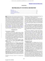
PRESSURE SWITCHES
Pressure-responsive switches have one or more power elements
(e.g., bellows, diaphragms, bourdon tubes) to produce the force
needed to operate the mechanism. Typically, pressure-switch power
The preparation of this chapter is assigned to TC 8.8, Refrigerant System
Controls and Accessories.
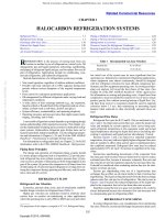
Fig. 1 Typical Pressure Switch
elements are all metal, although some miniaturized devices for specific applications, such as automotive air conditioning, may use synthetic diaphragms. Refrigerant pressure is applied directly to the
element, which moves against a spring that can be adjusted to control an operation at the desired pressure (Figure 1). If the control is
to operate in the subatmospheric (or vacuum) range, the bellows or
diaphragm force is sometimes reversed to act in the same direction
as the adjusting spring.
The force available for doing work (i.e., operating the switch
mechanism) in this control depends on the pressure in the system
and on the area of the bellows or diaphragm. With proper area,
enough force can be produced to operate heavy-duty switches. In
switches for high-pressure service, the minimum differential is relatively large because of the high-gradient-range spring required.
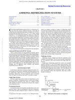
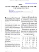
Miniaturized pressure switches may incorporate one or more
snap disks, which provide positive snap action of the electrical contacts. Snap-disk construction ensures consistent differential pressure between on and off settings (Figure 2); it also substantially
reduces electrical contact bounce or flutter, which can damage compressor clutch assemblies, relays, and electronic control modules.
Some snap-disk switches are built to provide multiple functions in
11.1
Copyright © 2010, ASHRAE
This file is licensed to Abdual Hadi Nema (). License Date: 6/1/2010
11.2
Fig. 2
2010 ASHRAE Handbook—Refrigeration (SI)
Miniaturized Pressure Switch
Fig. 3 Indirect Temperature Switch
Fig. 2 Miniaturized Pressure Switch
Table 1 Various Types of Pressure Switches
Type
Licensed for single user. © 2010 ASHRAE, Inc.
High-pressure cutout (HPCO)
High-side low-pressure (HSLP)
High-side fan-cycling (HSFC)
Low-side low-pressure (LSLP)
Low-side compressor cycling
(LSCC)
Lubricant pressure differential
failure (LPDF)
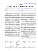
Fig. 3 Indirect Temperature Switch
Function
Stops compressor when excessive
pressure occurs
Prevents compressor operation under low
ambient or loss of refrigerant conditions
Cycles condenser fan on and off to
provide proper condenser pressure
Initiates defrost cycle; stops compressor
when low charge or system blockage
occurs
Cycles compressor on and off to provide
proper evaporator pressure and load
temperature
Stops compressor when difference
between oil pressure and crankcase
pressure is too low for adequate
lubrication
a single unit, such as high-pressure cutout (HPCO), high-side lowpressure (HSLP), and high-side fan-cycling (HSFC) switches.
Pressure switches in most refrigeration systems are used primarily to start and stop the compressor, cycle condenser fans, and initiate and terminate defrost cycles. Table 1 shows various types of
pressure switches with their corresponding functions.
TEMPERATURE SWITCHES (THERMOSTATS)
Temperature-responsive switches have one or more metal power
elements (e.g., bellows, diaphragms, bourdon tubes, bimetallic snap
disks, bimetallic strips) that produce the force needed to operate the
switch.
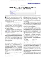
An indirect temperature switch is a pressure switch with the
pressure-responsive element replaced by a temperature-responsive
element. The temperature-responsive element is a hermetically
sealed system comprised of a flexible member (diaphragm or bellows) and a temperature-sensing element (bulb or tube) that are in
pressure communication with each other (Figure 3). The closed system contains a temperature-responsive fluid.
The exact temperature/pressure or temperature/volume relationship of the fluid used in the element allows the bulb temperature to
control the switch accurately. The switch is operated by changes in
pressure or volume that are proportional to changes in sensor temperature.
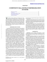
A direct temperature switch typically contains a bimetallic
disk or strip that activates electrical contacts when the temperature
increases or decreases. As its temperature increases or decreases,
the bimetallic element bends or strains because of the two metals’
Fig. 4
Direct Temperature Switch
Fig. 4
Direct Temperature Switch
different coefficients of thermal expansion, and the linked electrical
contacts engage or disengage. The disk bimetallic element provides
snap action, which results in rapid and positive opening or closing of
the electrical contacts, minimizing arcing and bounce. A bimetallic
strip (Figure 4) produces very slow contact action and is only suitable for use in very-low-energy electrical circuits. This type of
switch is typically used for thermal limit control because the switch
differentials and precision may be inadequate for many primary
refrigerant control requirements.
DIFFERENTIAL SWITCHES
Differential control switches typically maintain a given difference in pressure or temperature between two pipelines, spaces, or
loads. An example is the lubricant pressure differential failure
switch used with reciprocating compressors that use forced-feed
lubrication.
Figure 5 is a schematic of a differential switch that uses bellows
as power elements. Figure 6 shows a differential pressure switch
used to protect compressors against low oil pressure. These controls
have two elements (either pressure- or temperature-sensitive) simultaneously sensing conditions at two locations. As shown, the two
elements are rigidly connected by a rod, so that motion of one
causes motion of the other. The connecting rod operates contacts (as
shown). The scale spring is used to set the differential pressure at
which the device operates. At the control point, the sum of forces
developed by the low-pressure bellows and spring balances the
force developed by the high-pressure bellows.
Instrument differential is the difference in pressure or temperature between the low- and the high-pressure elements for which the
instrument is adjusted. Operating differential is the change in
This file is licensed to Abdual Hadi Nema (). License Date: 6/1/2010
Refrigerant-Control Devices
11.3
Fig. 5 Differential Switch Schematic
Fig. 7
Magnetic Float Switch
Fig. 5 Differential Switch Schematic
Licensed for single user. © 2010 ASHRAE, Inc.
Fig. 6
Differential Pressure Switch
Fig. 7
Magnetic Float Switch
maintained or monitored. The switch mechanism is generally hermetically sealed. Small heaters can be incorporated to prevent moisture from permeating the polycarbonate housing in cold operating
conditions. Other nonmechanical devices, such as capacitance
probes, use other methods to monitor the change in liquid level.
Operation and Selection
Fig. 6 Differential Pressure Switch
differential pressure or temperature required to open or close the
switch contacts. It is actually the change in instrument differential
from cut-in to cutout for any setting. Operating differential can be
varied by a second spring that acts in the same direction as the first
and takes effect only at the cut-in or cutout point without affecting
the other spring. A second method is adjusting the distance between
collars Z-Z on the connecting rod. The greater the distance between
them, the greater the operating differential.
If a constant instrument differential is required on a temperaturesensitive differential control switch throughout a large temperature
range, one element may contain a different temperature-responsive
fluid than the other.
A second type of differential-temperature control uses two sensing bulbs and capillaries connected to one bellows with a liquid fill.
This is known as a constant-volume fill, because the operating point
depends on a constant volume of the two bulbs, capillaries, and bellows. If the two bulbs have equal volume, a temperature rise in one
bulb requires an equivalent fall in the other’s temperature to maintain the operating point.
FLOAT SWITCHES
A float switch has a float ball, the movement of which operates
one or more sets of electrical contacts as the level of a liquid
changes. Float switches are connected by equalizing lines to the
vessel or an external column in which the liquid level is to be
Some float switches (Figure 7) operate from movement of a magnetic armature located in the field of a permanent magnet. Others
use solid-state circuits in which a variable signal is generated by liquid contact with a probe that replaces the float; this method is
adapted to remote-controlled applications and is preferred for
ultralow-temperature applications.
Application
The float switch can maintain or indicate the level of a liquid,
operate an alarm, control pump operation, or perform other functions. A float switch, solenoid liquid valve, and hand expansion
valve combination can control refrigerant level on the high- or lowpressure side of the refrigeration system in the same way that highor low-side float valves are used. The hand expansion valve, located
in the refrigerant liquid line immediately downstream of the solenoid valve, is initially adjusted to provide a refrigerant flow rate at
maximum load to keep the solenoid liquid valve in the open position
80 to 90% of the time; it need not be adjusted thereafter. From the
outlet side of the hand expansion valve, refrigerant passes through a
line and enters either the evaporator or the surge drum.
When the float switch is used for low-pressure level control,
precautions must be taken to provide a calm liquid level that falls in
response to increased evaporator load and rises with decreased
evaporator load. The same recommendations for insulation of the
body and liquid leg of the low-pressure float valve apply to the float
switch when it is used for refrigerant-level control on the lowpressure side of the refrigeration system. To avoid floodback, controls should be wired to prevent the solenoid liquid valve from
opening when the solenoid suction valve closes or the compressor
stops.
This file is licensed to Abdual Hadi Nema (). License Date: 6/1/2010
11.4
2010 ASHRAE Handbook—Refrigeration (SI)
CONTROL SENSORS
The control sensor is the component in a control system that
measures and signals the value of a parameter but has no direct function control. Control sensors typically require an auxiliary source of
energy for proper operation. They may be integrated into electronic
circuits that provide the required energy and condition the sensor’s
signal to accomplish the desired function control.
Licensed for single user. © 2010 ASHRAE, Inc.
PRESSURE TRANSDUCERS
Pressure transducers sense refrigerant pressure through a flexible
element (diaphragm, bourdon tube, or bellows) that is exposed to
the system refrigerant pressure. The pressure acts across the flexible
element’s effective area, producing a force that causes the flexible
element to strain against an opposing spring within the transducer.
The transducer uses a potentiometer, variable capacitor, strain gage,
or piezo element to translate the flexible element’s movement to a
proportional electrical output.
Transducers typically include additional electronic signal processing circuitry to temperature-compensate, modify, amplify, and
linearize the final analog electrical output. Typically, the outside of
the pressure-sensing flexible element is exposed to atmospheric
pressure and the transducer’s electrical output is proportional to the
refrigerant’s gage pressure. Transducers capable of measuring absolute pressure are also available.
Transducers are usually used as control sensors in electronic control systems, where the continuous analog pressure signal provides
data to comprehensive algorithm-based control strategies. For
example, in automotive air-conditioning systems, engine load management can be significantly enhanced. Based on a correlation
between refrigerant pressure and compressor torque requirements,
the electronic engine controller uses the transducer signal to regulate engine air and fuel flow, compensating for compressor load
variations. This improves fuel economy and eliminates the power
drain experienced when the compressor starts. Transducers also
provide a signal to electronically controlled variable-displacement
compressors to adjust refrigerant flow from the evaporator, preventing excessive cooling of the air and further improving fuel economy.
THERMISTORS
Thermistors are cost-effective and reliable temperature sensors.
They are typically small and are available in a variety of configurations and sheath materials. Thermistors are beads of semiconductor
materials with electrical resistances that change with temperature.
Materials with negative temperature coefficients (NTC) (i.e., resistance decreases as temperature increases) are frequently used. NTC
thermistors typically produce large changes in resistance with relatively small changes of temperature, and their characteristic curve is
nonlinear (Figure 8).
Fig. 8
Typical NTC Thermistor Characteristic
Thermistors are used in electronic control systems that linearize
and otherwise process their resistance change into function control
actions such as driving step motors or bimetallic heat motors for
function modulation. Their analog signal can also be conditioned to
perform start/stop functions such as energizing relays, contactors,
or solenoid valves.
RESISTANCE TEMPERATURE DETECTORS
Resistance temperature detectors (RTDs) are made of very fine
metal wire or films coiled or shaped into forms suitable for the
application. The elements may be mounted on a plate for surface
temperature measurements or encapsulated in a tubular sheath for
immersion or insertion into pressurized systems. Elements made of
platinum or copper have linear temperature-resistance characteristics over limited temperature ranges. Platinum, for example, is
linear within 0.3% from –18 to 150°C and minimizes long-term
changes caused by corrosion. RTDs are often mated with electronic
circuitry that produces a 4 to 20 mA current signal over a selected
temperature range. This arrangement eliminates error associated
with connecting line electrical resistance.
THERMOCOUPLES
Thermocouples are formed by the junction of two wires of dissimilar metals. The electromotive force between the wires depends
on the wire material and the junction temperature. When the wires
are joined at both ends, a thermocouple circuit is formed. When the
junctions are at different temperatures, an electric current proportional to the temperature difference between the two junctions flows
through the circuit. One junction, called the cold junction, is kept at
a constant known temperature (e.g., in an ice bath). The temperature
of the other (hot) junction is then determined by measuring the net
voltage in the circuit. Electronic circuitry is often arranged to provide a built-in cold junction and linearization of the net voltage-totemperature relationship. The resulting signal can then be electronically conditioned and amplified to implement function control.
LIQUID LEVEL SENSORS
Capacitance probes (Figure 9) can provide a continuous range
of liquid-level monitoring. They compare the impedance value of
the amount of probe wetted with liquid refrigerant to that in the
vapor space. The output can be converted to a variable signal and
sent to a dedicated control device with multiple switch points or a
computer/programmable logic controller (PLC) for programming
or monitoring the refrigerant level. These probes can replace multiple float switches and provide easy level adjustability.
Operation and Selection
The basic principle is that the electrical capacitance of a vertical
conducting rod, centered within a vertical conducting cylinder, varies approximately in proportion to the liquid level in the enclosure.
The capability to accomplish this depends on the significant difference between the dielectric constants of the liquid and the vapor
above the liquid surface.
Capacitance probes are available in a variety of configurations,
using a full range of refrigerants. Active lengths vary from 150 mm
to 4 m; output signals vary from 0 to 5 or 1 to 6 V, 4 to 20 mA, or digital readout. Operating temperatures range from –73.3 to 65.6°C.
Both internal and external vessel mountings are available.
CONTROL VALVES
Fig. 8 Typical NTC Thermistor Characteristic
Control valves are used to start, stop, direct, and modulate refrigerant flow to satisfy system requirements in accordance with load
requirements. To ensure satisfactory performance, valves should be
This file is licensed to Abdual Hadi Nema (). License Date: 6/1/2010
Refrigerant-Control Devices
Fig. 8 Capacitance Probe in (A) Vertical Receiver and (B)
Auxiliary Level Column
11.5
operated by superheat and responds to changes in superheat, a portion of the evaporator must be used to superheat refrigerant gas.
Unlike the constant-pressure valve, the thermostatic expansion
valve is not limited to constant-load applications. It is used for controlling refrigerant flow to all types of direct-expansion evaporators
in air-conditioning and in commercial (medium-temperature), lowtemperature, and ultralow-temperature refrigeration applications.
Operation
Figure 10 shows a schematic cross section of a typical thermostatic expansion valve, with the principal components identified.
The following pressures and their equivalent forces govern thermostatic expansion valve operation:
Licensed for single user. © 2010 ASHRAE, Inc.
P1 = pressure of thermostatic element (a function of bulb’s
charge and temperature), which is applied to top of
diaphragm and acts to open valve
P2 = evaporator pressure, which is applied under diaphragm
through equalizer passage and acts in closing direction
P3 = pressure equivalent of superheat spring force, which is
applied underneath diaphragm and is also a closing force
Fig. 9 Capacitance Probe in (A) Vertical Receiver and
(B) Auxiliary Level Column
Fig. 9
Typical Thermostatic Expansion Valve
Fig. 10
Typical Thermostatic Expansion Valve
protected from foreign material, excessive moisture, and corrosion
by properly sized strainers, filters, and/or filter-driers.
THERMOSTATIC EXPANSION VALVES
The thermostatic expansion valve controls the flow of liquid
refrigerant entering the evaporator in response to the superheat of
gas leaving the evaporator. It keeps the evaporator active without
allowing liquid to return through the suction line to the compressor.
This is done by controlling the mass flow of refrigerant entering the
evaporator so it equals the rate at which it can be completely vaporized in the evaporator by heat absorption. Because this valve is
At any constant operating condition, these pressures (forces) are
balanced and P1 = P2 + P3.
An additional force, which is small and not considered fundamental, arises from the pressure differential across the valve port. To
a degree, it can affect thermostatic expansion valve operation. For
the configuration shown in Figure 11, the force resulting from port
imbalance is the product of pressure drop across the port and the
area of the port; it is an opening force in this configuration. In other
designs, depending on the direction of flow through the valve, port
imbalance may result in a closing force.
The principal effect of port imbalance is on the stability of valve
control. As with any modulating control, if the ratio of the diaphragm area to the port is kept large, the unbalanced port effect is
minor. However, if this ratio is small or if system operating conditions require, a balanced port valve can be used. Figure 11 shows a
typical balanced port design.
Figure 12 shows an evaporator operating with R-410A at a saturation temperature of 4°C [814 kPa (gage)]. Liquid refrigerant
enters the expansion valve, is reduced in pressure and temperature at
the valve port, and enters the evaporator at point A as a mixture of
saturated liquid and vapor. As flow continues through the evaporator, more of the refrigerant is evaporated. Assuming there is no pressure drop, the refrigerant temperature remains at 4°C until the liquid
is entirely evaporated at point B. From this point, additional heat
absorption increases the temperature and superheats the refrigerant
gas, while the pressure remains constant at 814 kPa, until, at point C
(the outlet of the evaporator), the refrigerant gas temperature is
10°C. At this point, the superheat is 6 K (10 – 4°C).
An increased heat load on the evaporator increases the temperature of refrigerant gas leaving the evaporator. The bulb of the valve
senses this increase, and the thermostatic charge pressure P1
increases and causes the valve to open wider. The increased flow
results in a higher evaporator pressure P2, and a balanced control
point is again established. Conversely, decreased heat load on the
evaporator decreases the temperature of refrigerant gas leaving the
evaporator and causes the thermostatic expansion valve to start
closing.
The new control point, after an increase in valve opening, is at a
slightly higher operating superheat because of the spring rate of the
diaphragm and superheat spring. Conversely, decreased load results
in an operating superheat slightly lower than the original control
point.
These superheat changes in response to load changes are illustrated by the gradient curve of Figure 13. Superheat at no load, distance 0-A, is called static superheat and ensures sufficient spring
force to keep the valve closed during system shutdown. An increase
This file is licensed to Abdual Hadi Nema (). License Date: 6/1/2010
11.6
Licensed for single user. © 2010 ASHRAE, Inc.
Fig. 10 Typical Balanced Port Thermostatic Expansion Valve
2010 ASHRAE Handbook—Refrigeration (SI)
Fig. 11
Valves
Typical Gradient Curve for Thermostatic Expansion
Fig. 13 Typical Gradient Curve for Thermostatic
Expansion Valves
Fig. 11 Typical Balanced Port Thermostatic Expansion Valve
Fig. 10 Thermostatic Expansion Valve Controlling Flow of
Liquid R-410A Entering Evaporator, Assuming R-410A
Charge in Bulb
Fig. 12 Thermostatic Expansion Valve Controlling
Flow of Liquid R-410A Entering Evaporator, Assuming
R-410A Charge in Bulb
in valve capacity or load is approximately proportional to superheat
until the valve is fully open. Opening superheat, represented by the
distance A-B, is the superheat increase required to open the valve to
match the load; operating superheat is the sum of static and opening
superheats.
Capacity
The factory superheat setting (static superheat setting) of thermostatic expansion valves is made when the valve starts to open.
Valve manufacturers establish capacity ratings on the basis of opening superheat, typically from 2 to 4 K, depending on valve design,
size, and application. Full-open capacities usually exceed rated
capacities by 10 to 40% to allow a reserve, represented by the distance B-C in Figure 13, for manufacturing tolerances and application contingencies.
A valve should not be selected on the basis of its reserve capacity,
which is available only at higher operating superheat. The added
superheat may have an adverse effect on performance. Because
valve gradients used for rating purposes are selected to produce
optimum modulation for a given valve design, manufacturers’ recommendations should be followed.
Thermostatic expansion valve capacities are normally published
for various evaporator temperatures and valve pressure drops. (See
AHRI Standard 750 and ASHRAE Standard 17 for testing and rating methods.) Nominal capacities apply at 4°C evaporator temperature. Capacities are reduced at lower evaporator temperatures.
These capacity reductions result from the changed refrigerant pressure/temperature relationship at lower temperatures. For example, if
R-410A is used, the change in saturated pressure between 4 and 7°C
is 81.4 kPa, whereas between –29 and –26°C the change is 33.8 kPa.
Although the valve responds to pressure changes, published capacities are based on superheat change. Thus, the valve opening and,
consequently, valve capacity are less for a given superheat change at
lower evaporator temperatures.
Pressure drop across the valve port is always the net pressure
drop available at the valve, rather than the difference between compressor discharge and compressor suction pressures. Allowances
must be made for the following:
• Pressure drop through condenser, receiver, liquid lines, fittings,
and liquid line accessories (filters, driers, solenoid valves, etc.).
• Static pressure in a vertical liquid line. If the thermostatic expansion valve is at a higher level than the receiver, there will be a
pressure loss in the liquid line because of the static pressure of
liquid.
• Distributor pressure drop.
• Evaporator pressure drop.
• Pressure drop through suction line and accessories, such as evaporator-pressure regulators, solenoid valves, accumulators, etc.
Variations in valve capacity related to changes in system conditions are approximately proportional to the following relationship:
q = C p (hg – hf)
where
q = refrigerating effect
(1)
This file is licensed to Abdual Hadi Nema (). License Date: 6/1/2010
Refrigerant-Control Devices
C
p
hg
hf
=
=
=
=
=
thermostatic expansion valve flow constant
entering liquid density
valve pressure difference
enthalpy of vapor exiting evaporator
enthalpy of liquid entering thermostatic expansion valve
Thermostatic expansion valve capacity is dependent on vaporfree liquid entering the valve. If there is flash gas in the entering liquid, valve capacity is reduced substantially because
• Refrigerant mass flow passing through the valve is significantly
diminished because the two-phase flow has a lower density
• Flow of the compressible vapor fraction chokes at pressure ratios
that typically exist across expansion valves and further restricts
liquid-phase flow rate
• Vapor passing through the valve provides no refrigerating effect
Flashing of liquid refrigerant may be caused by pressure drop in
the liquid line, filter-drier, vertical lift, or a combination of these. If
refrigerant subcooling at the valve inlet is not adequate to prevent
flash gas from forming, additional subcooling means must be provided.
Licensed for single user. © 2010 ASHRAE, Inc.
Thermostatic Charges
There are several principal types of thermostatic charges, each
with certain advantages and limitations.
Gas Charge. Conventional gas charges are limited liquid charges
that use the same refrigerant in the thermostatic element that is used
in the refrigeration system. The amount of charge is such that, at a
predetermined temperature, all of the liquid has vaporized and any
temperature increase above this point results in practically no
increase in element pressure. Figure 14 shows the pressure/
temperature relationship of the R-134a gas charge in the thermostatic
element. Because of the characteristic pressure-limiting feature of its
thermostatic element, the gas-charged valve can provide compressor
motor overload protection on some systems by limiting the maximum operating suction pressure (MOP). It also helps prevent floodback (return of refrigerant liquid to the compressor through the
suction line) on starting. Increasing the superheat setting lowers the
maximum operating suction pressure; decreasing the superheat setting raises the MOP because the superheat spring and evaporator
pressure balance the element pressure through the diaphragm.
Gas-charged valves must be carefully applied to avoid loss of
control from the bulb. If the diaphragm chamber or connecting tube
Fig. 11 Pressure-Temperature Relationship of R-134a Gas
Charge in Thermostatic Element
11.7
becomes colder than the bulb, the small amount of charge in the bulb
condenses at the coldest point. This results in the valve throttling or
closing, as detailed in the section on Application.
Liquid Charge. Straight liquid charges use the same refrigerant
in the thermostatic element and refrigeration system. The volumes
of the bulb, bulb tubing, and diaphragm chamber are proportioned
so that the bulb contains some liquid under all temperatures. Therefore, the bulb always controls valve operation, even with a colder
diaphragm chamber or bulb tubing.
The straight liquid charge (Figure 15) results in increased operating superheat as evaporator temperature decreases. This usually
limits use of the straight liquid charge to moderately high evaporator
temperatures. The valve setting required for a reasonable operating
superheat at a low evaporator temperature may cause floodback during cooling from normal ambient temperatures.
Liquid Cross Charge. Liquid cross charges use a volatile liquid
that can be mixed with a noncondensable gas in the thermostatic element that is different from the refrigerant in the system. Cross
charges have flatter pressure/temperature curves than the system
refrigerants with which they are used. Consequently, their superheat
characteristics differ considerably from those of straight liquid or
gas charges.
Cross charges in the commercial temperature range generally
have superheat characteristics that are nearly constant or that deviate only moderately through the evaporator temperature range. This
charge, also illustrated in Figure 15, is generally used in the evaporator temperature range of 4 to –18°C or slightly below.
For evaporator temperatures substantially below –18°C, a more
extreme cross charge may be used. At high evaporator temperatures,
the valve controls at a high superheat. As the evaporator temperature
falls to the normal operating range, the operating superheat also falls
to normal. This prevents floodback on starting, reduces load on the
compressor motor at start-up, and allows rapid pulldown of suction
pressure. To avoid floodback, valves with this type of charge must
be set for the optimum operating superheat at the lowest evaporator
temperature expected.
Gas Cross Charge. Gas cross charges combine features of the
gas charge and liquid cross charge. They use a limited amount of liquid, thereby providing a maximum operating pressure. The liquid
used in the charge is often mixed with a noncondensable gas such as
air or nitrogen and is different from the refrigerant in the system; it
is chosen to provide superheat characteristics similar to those of the
liquid cross charges (low temperature). Consequently, they provide
both the superheat characteristics of a cross charge and the maximum operating pressure of a gas charge (Figure 15).
Adsorption Charge. Typical adsorption charges depend on the
property of an adsorbent, such as silica gel or activated carbon, that
is used in an element bulb to adsorb and desorb a gas such as carbon
dioxide, with accompanying changes in temperature. The amount of
adsorption or desorption changes the pressure in the thermostatic
element. Because adsorption charges respond primarily to the temperature of the adsorbent material, they are the charges least
affected by the ambient temperature surrounding the bulb, bulb tubing, and diaphragm chamber. The comparatively slow thermal
response of the adsorbent results in a charge characterized by its
stability. Superheat characteristics can be varied by using different
charge fluids, adsorbents, and/or charge pressures. The pressurelimiting feature of the gas or gas cross charges is not available with
the adsorption element.
Type of Equalization
Fig. 14 Pressure/Temperature Relationship of R-134a Gas
Charge in Thermostatic Element
Internal Equalizer. When the refrigerant pressure drop through
an evaporator is relatively low (e.g., equivalent to 1 K change in saturation temperature), a thermostatic expansion valve that has an
internal equalizer may be used. Internal equalization describes
valve outlet pressure transmitted through an internal passage to the
underside of the diaphragm (see Figure 10).
This file is licensed to Abdual Hadi Nema (). License Date: 6/1/2010
11.8
2010 ASHRAE Handbook—Refrigeration (SI)
Fig. 11 Typical Superheat Characteristics of Common Thermostatic Charges
Fig. 13 Pilot-Operated Thermostatic Expansion Valve Controlling Liquid Refrigerant Flow to Direct-Expansion Chiller
Fig. 17 Pilot-Operated Thermostatic Expansion Valve
Controlling Liquid Refrigerant Flow to
Direct-Expansion Chiller
Fig. 15
Typical Superheat Characteristics of Common
Thermostatic Charges
Licensed for single user. © 2010 ASHRAE, Inc.
Fig. 12 Bulb Location for Thermostatic Expansion Valve
Fig. 16 Bulb Location for Thermostatic Expansion Valve
Pressure drop in many evaporators is greater than the 1 K equivalent. When a refrigerant distributor is used, pressure drop across
the distributor causes pressure at the expansion valve outlet to be
considerably higher than that at the evaporator outlet. As a result, an
internally equalized valve controls at an abnormally high superheat.
Under these conditions, the evaporator does not perform efficiently
because it is starved for refrigerant. Furthermore, the distributor
pressure drop is not constant, but varies with refrigerant flow rate
and therefore cannot be compensated for by adjusting the superheat
setting of the valve.
External Equalizer. Because evaporator and/or refrigerant distributor pressure drop causes poor system performance with an
internally equalized valve, a valve that has an external equalizer is
used. Instead of the internal communicating passage shown in Figure 10, an external connection to the underside of the diaphragm is
provided. The external equalizer line is connected either to the suction line, as shown in Figure 16, or into the evaporator at a point
downstream from the major pressure drop.
Alternative Construction Types
Pilot-operated thermostatic expansion valves are used on large
systems in which the required capacity per valve exceeds the range
of direct-operated valves. The pilot-operated valve consists of a
piston-type pilot-operated regulator, which is used as the main
expansion valve, and a low-capacity thermostatic expansion valve,
which serves as an external pilot valve. The small pilot thermostatic
expansion valve supplies pressure to the piston chamber or, depending on the regulator design, bleeds pressure from the piston chamber
in response to a change in the operating superheat. Pilot operation
allows the use of a characterized port in the main expansion valve to
provide good modulation over a wide load range. Therefore, a very
carefully applied pilot-operated valve can perform well on refrigerating systems that have some form of compressor capacity reduction, such as cylinder unloading. Figure 17 illustrates such a valve
applied to a large-capacity direct-expansion chiller.
The auxiliary pilot controls should be sized to handle only the
pilot circuit flow. For example, in Figure 17 a small solenoid valve
in the pilot circuit, installed ahead of the thermostatic expansion
valve, converts the pilot-operated valve into a stop valve when the
solenoid valve is closed.
Equalization Features. When the compressor stops, a thermostatic expansion valve usually moves to the closed position. This
movement sustains the difference in refrigerant pressures in the
evaporator and the condenser. Low-starting-torque motors require
that these pressures be equalized to reduce the torque needed to
restart the compressor. One way to provide pressure equalization is
to add, parallel to the main valve port, a small fixed auxiliary passageway, such as a slot or drilled hole in the valve seat or valve pin.
This opening allows limited fluid flow through the control, even
when the valve is closed, and allows the system pressures to equalize on the off cycle. The size of a fixed auxiliary passageway must
be limited so its flow capacity is not greater than the smallest flow
that must be controlled in normal system operation. For a drilled
hole, the hole’s diameter should be bigger than the maximum allowable particle size circulating in the system, to prevent permanent
obstructions. Slots in the seat may be a more robust solution,
because any particle obstructing the slot would be flushed when the
expansion valve opens fully.
Another, more complex control is available for systems requiring
shorter equalizing times than can be achieved with the fixed auxiliary passageway. This control incorporates an auxiliary valve port,
which bypasses the primary port and is opened by the element diaphragm as it moves toward and beyond the position at which the primary valve port is closed. Flow capacity of an auxiliary valve port
can be considerably larger than that of the fixed auxiliary passageway, so pressures can equalize more rapidly.
Flooded System. Thermostatic expansion valves are seldom
applied to flooded evaporators because superheat is necessary for
proper valve control; only a few degrees of suction vapor superheat
in a flooded evaporator incurs a substantial loss in system capacity.
If the bulb is installed downstream from a liquid-to-suction heat
exchanger, a thermostatic expansion valve can be made to operate at
this point on a higher superheat. Valve control is likely to be poor
because of the variable rate of heat exchange as flow rates change
(see the section on Application).
Some expansion valves have modified thermostatic elements in
which electric heat is supplied to the bulb. The bulb is inserted in
direct contact with refrigerant liquid in a low-side accumulator. The
contact of cold refrigerant liquid with the bulb overrides the artificial heat source and throttles the expansion valve. As liquid falls
This file is licensed to Abdual Hadi Nema (). License Date: 6/1/2010
Refrigerant-Control Devices
away from the bulb, the valve feed increases again. Although similar in construction to a thermostatic expansion valve, it is essentially
a modulating liquid-level control valve.
Desuperheating Valves. Thermostatic expansion valves with
special thermostatic charges are used to reduce gas temperatures
(superheat) on various air-conditioning and refrigeration systems.
Suction gas in a single-stage system can be desuperheated by injecting liquid directly into the suction line. This cooling may be
required with or without discharge gas bypass used for compressor
capacity control. The line upstream of the valve bulb must be long
enough so the injected liquid refrigerant can mix adequately with
the gas being desuperheated. On compound compression systems, a
specially selected expansion valve may be used to inject liquid
directly into the interstage line upstream of the valve bulb to provide
intercooling.
Licensed for single user. © 2010 ASHRAE, Inc.
Application
Hunting is alternate overfeeding and starving of the refrigerant
feed to the evaporator. It produces sustained cyclic changes in the
pressure and temperature of the refrigerant gas leaving the evaporator. Extreme hunting reduces refrigeration system capacity because
mean evaporator pressure and temperature are lowered and compressor capacity is reduced. If overfeeding of the expansion valve
causes intermittent flooding of liquid into the suction line, the compressor may be damaged.
Although hunting is commonly attributed to the thermostatic
expansion valve, it is seldom solely responsible. One reason for
hunting is that all evaporators have a time lag. When the bulb signals
for a change in refrigerant flow, the refrigerant must traverse the
entire evaporator before a new signal reaches the bulb. This lag or
time lapse may cause continuous overshooting of the valve both
opening and closing. In addition, the thermostatic element, because
of its mass, has a time lag that may be in phase with the evaporator
lag and amplify the original overshooting.
It is possible to alter the thermostatic element’s response rate by
either using thermal ballast or changing the mass or heat capacity of
the bulb, thereby damping or even eliminating hunting. A change in
valve gradient may produce similar result.
Slug flow or percolation in the evaporator can also cause hunting.
Under these conditions, liquid refrigerant moves in waves (slugs)
that fill a portion of the evaporator tube and erupt into the suction
line. These unevaporated slugs chill the bulb and temporarily reduce
the feed of the valve, resulting in intermittent starving of the evaporator.
On multiple-circuit evaporators, a lightly loaded or overfed circuit also floods into the suction line, chills the bulb, and throttles the
valve. Again, the effect is intermittent; when the valve feed is
reduced, flooding ceases and the valve reopens.
Hunting can be minimized or avoided in the following ways:
• Select the proper valve size from the valve capacity ratings rather
than nominal valve capacity; oversized valves aggravate hunting.
• Change the valve adjustment. A lower superheat setting usually
(but not always) increases hunting.
• Select the correct thermostatic element charge. Cross-charged
elements are less susceptible to hunting.
• Design the evaporator section for even flow of refrigerant and air.
Uniform heat transfer from the evaporator is only possible if
refrigerant is distributed by a properly selected and applied refrigerant distributor and air distribution is controlled by a properly
designed housing. (Air-cooling and dehumidifying coils, including refrigerant distributors, are detailed in Chapter 22 of the 2008
ASHRAE Handbook—HVAC Systems and Equipment.)
• Size and arrange suction piping correctly.
• Locate and apply the bulb correctly.
• Select the best location for the external equalizer line connection.
11.9
Bulb Location. Most installation requirements are met by strapping the bulb to the suction line to obtain good thermal contact
between them. Normally, the bulb is attached to a horizontal line
upstream of the external equalizer connection (if used) at a 3 or 9
o’clock position as close to the evaporator as possible. The bulb is
not normally placed near or after suction-line traps, but some
designers test and prove locations that differ from these recommendations. A good moisture-resistant insulation over the bulb and
suction line diminishes the adverse effect of varying ambient temperatures at the bulb location.
Occasionally, the bulb of the thermostatic expansion valve is
installed downstream from a liquid-suction heat exchanger to compensate for a capacity shortage caused by an undersized evaporator.
Although this procedure seems to be a simple method of maximizing evaporator capacity, installing the bulb downstream of the heat
exchanger is undesirable from a control standpoint. As the valve
modulates, the liquid flow rate through the heat exchanger changes,
causing the rate of heat transfer to the suction vapor to change. An
exaggerated valve response follows, resulting in hunting. There
may be a bulb location downstream from the heat exchanger that
reduces the hunt considerably. However, the danger of floodback to
the compressor normally overshadows the need to attempt this
method.
Certain installations require increased bulb sensitivity as a protection against floodback. The bulb, if located properly in a well in
the suction line, has a rapid response because of its direct contact
with the refrigerant stream. Bulb sensitivity can be increased by
using a bulb smaller than is normally supplied. However, use of the
smaller bulb is limited to gas-charged valves. Good piping practice
also affects expansion valve performance.
Figure 18 illustrates the proper piping arrangement when the
suction line runs above the evaporator. A lubricant trap that is as
short as possible is located downstream from the bulb. The vertical
riser(s) must be sized to produce a refrigerant velocity that ensures
continuous return of lubricant to the compressor. The terminal end
of the riser(s) enters the horizontal run at the top of the suction line;
this avoids interference from overfeeding any other expansion valve
or any drainback during the off cycle.
If circulated with lubricant-miscible refrigerant, a heavy concentration of lubricant elevates the refrigerant’s boiling temperature.
The response of the thermostatic charge of the expansion valve is
related to the saturation pressure and temperature of pure refrigerant. In an operating system, the false pressure/temperature signals
of lubricant-rich refrigerants cause floodback or operating superheats considerably lower than indicated, and quite often cause
erratic valve operation. To keep lubricant concentration at an
acceptable level, either the lubricant pumping rate of the compressor must be reduced or an effective lubricant separator must be used.
Fig. 14 Bulb Location When Suction Main is Above Evaporator
Fig. 18 Bulb Location When Suction Main is Above
Evaporator
This file is licensed to Abdual Hadi Nema (). License Date: 6/1/2010
Licensed for single user. © 2010 ASHRAE, Inc.
11.10
2010 ASHRAE Handbook—Refrigeration (SI)
The external equalizer line is ordinarily connected at the evaporator outlet, as shown in Figure 18. It may also be connected at the
evaporator inlet or at any other point in the evaporator downstream
of the major pressure drop. On evaporators with long refrigerant circuits that have inherent lag, hunting may be minimized by changing
the connection point of the external equalizer line.
In application, the various parts of the valve’s thermostatic element are simultaneously exposed to different thermal influences
from the surrounding ambient air and the refrigerant system. In
some situations, cold refrigerant exiting the valve dominates and
cools the thermostatic element to below the bulb temperature. When
this occurs with a gas-charged or gas cross-charged valve, the
charge condenses at the coldest point in the element and control of
refrigerant feed moves from the bulb to the thermostatic element
(diaphragm chamber). Pressure applied to the top of the diaphragm
diminishes to saturation pressure at the cold point. Extreme starving
of the evaporator, progressing to complete cessation of refrigerant
flow, is characteristic. For this reason, gas-charged or gas crosscharged valves should be applied only to multicircuited evaporators
that use refrigerant distributors. The distributor typically provides
sufficient pressure drop to maintain a saturation temperature at the
valve outlet well above the temperature at the bulb location.
Internally equalized gas-charged or gas cross-charged valves
should only be considered in very carefully selected applications
where the risk of loss of control can be minimized. Some gas crosscharge formulations may be slightly less susceptible to the
described loss of control than are straight gas charges, but they are
far from immune. Gas-charged and gas cross-charged valves with
specially constructed thermostatic power elements that positively
isolate the charge fluids in the temperature-sensing element (bulb)
have been applied in situations where there was high risk of control
loss and the pressure-limiting feature of a gas-charged valve was
required.
Gas-charged bulbless valves, frequently called block valves
(Figure 19), are practically immune to loss of control because the
thermostatic element (diaphragm chamber) is located at the evaporator outlet. The valve is constructed so that the temperature-sensing
function of the remote bulb is integrated into the thermostatic element by purposely confining all of the charge fluid to this chamber.
Liquid, liquid cross-charged, and adsorption-charged valves are
not susceptible to the same type of loss of control that gas-charged
or gas cross-charged valves are. However, exposure to extreme
ambient temperature environments causes shifting of operating
Fig. 15 Typical Block Valve
superheats. The degree of superheat shift depends on the severity of
the thermal exposure. High ambient temperatures surrounding thermally sensitive parts of the valve typically lower operating superheats, and vice versa. Gas-charged and gas cross-charged valves,
including bulbless or block valves, respond to high ambient exposure similarly but starve the evaporator when exposed to ambient
temperatures below evaporator outlet refrigerant temperatures.
ELECTRIC EXPANSION VALVES
Application of an electric expansion valve requires a valve, controller, and control sensors. The control sensors may include pressure transducers, thermistors, resistance temperature devices
(RTDs), or other pressure and temperature sensors. See Chapter 36
in the 2009 ASHRAE Handbook—Fundamentals for a discussion of
instrumentation. Specific types should be discussed with the electric
valve and electronic controller manufacturers to ensure compatibility of all components.
Electric valves typically have four basic types of actuation:
•
•
•
•
Heat-motor operated
Magnetically modulated
Pulse-width-modulated (on/off type)
Step-motor-driven
Heat-motor valves may be one of two types. In one type, one or
more bimetallic elements are heated electrically, causing them to
deflect. The bimetallic elements are linked mechanically to a valve
pin or poppet; as the bimetallic element deflects, the valve pin or
poppet follows the element movement. In the second type, a volatile
fluid is contained within an electrically heated chamber so that the
regulated temperature (and pressure) is controlled by electrical
power input to the heater. The regulated pressure acts on a diaphragm or bellows, which is balanced against atmospheric air pressure or refrigerant pressure. The diaphragm is linked to a pin or
poppet, as shown in Figure 20.
A magnetically modulated (analog) valve functions by modulation of an electromagnet; a solenoid armature compresses a spring
progressively as a function of magnetic force (Figure 21). The modulating armature may be connected to a valve pin or poppet directly
or may be used as the pilot element to operate a much larger valve.
When the modulating armature operates a pin or poppet directly, the
valve may be of a pressure-balanced port design so that pressure
differential has little or no influence on valve opening.
The pulse-width-modulated valve is an on/off solenoid valve
with special features that allow it to function as an expansion valve
through a life of millions of cycles (Figure 22). Although the valve
is either fully opened or closed, it operates as a variable metering
device by rapidly pulsing the valve open and closed. For example, if
50% flow is needed, the valve will be open 50% of the time and
Fig. 16
Fig. 19 Typical Block Valve
Fluid-Filled Heat-Motor Valve
Fig. 20 Fluid-Filled Heat-Motor Valve
This file is licensed to Abdual Hadi Nema (). License Date: 6/1/2010
Refrigerant-Control Devices
Fig. 17 Magnetically Modulated Valve
11.11
Fig. 20 Electronically Controlled, Electrically Operated
Evaporator-Pressure Regulator
Fig. 24 Electronically Controlled, Electrically Operated
Evaporator-Pressure Regulator
Fig. 21 Magnetically Modulated Valve
Licensed for single user. © 2010 ASHRAE, Inc.
Fig. 18 Pulse-Width Modulated Valve
Fig. 22
Fig. 19
Pulse-Width-Modulated Valve
Step Motor with (A) Lead Screw and (B) Stem Seal
Fig. 23 Step Motor with (A) Lead Screw and (B) Gear Drive
with Stem Seal
closed 50% of the time. The duration of each opening, or pulse, is
regulated by the electronics.
A step motor is a multiphase motor designed to rotate in discrete
fractions of a revolution, based on the number of signals or “steps”
sent by the controller. The controller tracks the number of steps and
can offer fine control of the valve position with a high level of
repeatability. Step motors are used in instrument drives, plotters,
and other applications where accurate positioning is required. When
used to drive expansion valves, a lead screw changes the rotary
motion of the rotor to a linear motion suitable for moving a valve pin
or poppet (Figure 23A). The lead screw may be driven directly from
the rotor, or a reduction gearbox may be placed between the motor
and lead screw. The motor may be hermetically sealed within the
refrigerant environment, or the rotor may be enclosed in a thinwalled, nonmagnetic, pressuretight metal tube, similar to those used
in solenoid valves, which is surrounded by the stator such that the
rotor is in the refrigerant environment and the stator is outside the
refrigerant environment. In some designs, the motor and gearbox
can operate outside the refrigerant system with an appropriate stem
seal (Figure 23B).
Electric expansion valves may be controlled by either digital or
analog electronic circuits. Electronic control gives additional flexibility over traditional mechanical valves to consider control
schemes that would otherwise be impossible, including stopped or
full flow when required.
The electric expansion valve, with properly designed electronic
controllers and sensors, offers a refrigerant flow control means that
is not refrigerant specific, has a very wide load range, can often be
set remotely, and can respond to a variety of input parameters.
REGULATING AND
THROTTLING VALVES
Regulating and throttling valves are used in refrigeration systems
to perform a variety of functions. Valves that respond to and control
their own inlet pressure are called upstream pressure regulators.
This type of regulator, when located in an evaporator vapor outlet
line, responds to evaporator outlet pressure and is commonly called
an evaporator-pressure regulator. A special three-way version of
an upstream pressure regulator is designed specifically for aircooled condenser pressure regulation during cold-weather operation. Valves that respond to and control their own outlet pressure are
called downstream pressure regulators. Downstream pressure
regulators located in a compressor suction line regulate compressor
suction pressure and may also be called suction-pressure regulators,
crankcase pressure regulators, or holdback valves; they are typically
used to prevent compressor motor overload. A downstream pressure
regulator located at an evaporator inlet to feed liquid refrigerant into
the evaporator at a constant evaporator pressure is known as a
constant-pressure or automatic expansion valve.
A third category of pressure regulator, a differential pressure
regulator, responds to the difference between its own inlet and outlet pressures.
Electronically controlled, electrically operated evaporatorpressure-regulating valves have been developed to control temperature in food merchandising refrigerators and other refrigerated
spaces (Figure 24). This type of valve regulates evaporator pressure,
although it typically responds to temperature in the space or load as
well as pressure in the evaporator or suction line, rather than pressure alone. The system consists of a temperature sensor, pressure
transducer, and an electronic control circuit that has been programmed by the manufacturer with a control strategy or algorithm,
and an electrically driven evaporator-pressure-regulating valve. The
set point may be set or changed on site or at a remote location
through communication software. The valve responds to the difference between set-point temperature and the sensed temperature in
the space or load. A sensed temperature above the set point drives
This file is licensed to Abdual Hadi Nema (). License Date: 6/1/2010
11.12
the valve further open, thereby reducing evaporator pressure and
saturation temperature; a sensed temperature below set point modulates the valve in the closing direction, which increases evaporator
pressure. During defrost, the control circuit usually closes the valve.
Additional information on the drive and sensing mechanisms used
with this valve type is given in the sections on Electric Expansion
Valves and on Control Sensors.
Electronically controlled pressure-regulating valves may also be
used in various other applications, such as discharge gas bypass
capacity reduction, compressor suction throttling, condenser pressure regulation, gas defrost systems, and heat reclaim schemes.
2010 ASHRAE Handbook—Refrigeration (SI)
Fig. 21
Direct-Operated Evaporator-Pressure Regulator
Licensed for single user. © 2010 ASHRAE, Inc.
EVAPORATOR-PRESSURE-REGULATING VALVES
The evaporator-pressure regulator is a regulating valve designed
to control its own inlet pressure. Typically installed in the suction
line exiting an evaporator, it regulates that evaporator’s outlet pressure, which is the regulator’s upstream or inlet pressure. For this reason evaporator-pressure regulators are also called upstream
pressure regulators. They are most frequently used to prevent
evaporator pressure (and saturation temperature) from dropping
below a desired minimum. As declining regulator inlet pressure
approaches the regulator set point, the valve throttles, thereby maintaining the desired minimum evaporator pressure (and temperature).
Evaporator-pressure regulators are often used to balance evaporator
capacity with varying load conditions and to protect against freezing at low loads, such as in water chillers.
The work required to drive pilot-operated valves is most commonly produced by harnessing the pressure loss caused by flow
through the valve. Direct-operated regulating valves are powered by
relatively large changes in the controlled variable (in this case, inlet
pressure). Pilot- and direct-operated evaporator-pressure regulators
may be classified as self-powered. Evaporator-pressure regulators
are sometimes driven by a high-pressure refrigerant liquid or gas
flowing from the system’s high-pressure side, as well as electrically.
These types are usually considered to be externally powered.
Fig. 25 Direct-Operated Evaporator-Pressure Regulator
Fig. 22 Pilot-Operated Evaporator-Pressure Regulator (SelfPowered)
Operation
Direct-operated evaporator-pressure-regulating valves are
relatively simple, as shown in Figure 25. The inlet pressure acts on
the bottom of the seat disk and opposes the spring. The outlet pressure acts on the bottom of the bellows and the top of the seat disc.
Because the effective areas of the bellows and the port are equal,
these two forces cancel each other, and the valve responds to inlet
pressure only. When the inlet pressure rises above the equivalent
pressure exerted by the spring force, the valve begins to open. When
inlet pressure falls, the spring moves the valve in the closing direction. In operation, the valve assumes an intermediate throttling position that balances the refrigerant flow rate with evaporator load.
Because both spring and bellows must be compressed through
the entire opening valve stroke, a significant change in inlet pressure
is required to open the valve to its rated capacity. Inlet pressure
changes of 35 to 70 kPa or more, depending on design, are typically
required to move direct-operated evaporator-pressure regulators
from closed position to their rated flow capacity. Therefore, these
valves have relatively high gradients and the system may experience
significant changes in regulated evaporator pressure when large
load changes occur.
Pilot-operated evaporator-pressure-regulating valves are
either self-powered or high-pressure-driven. The self-powered regulator (Figure 26) starts to open when the inlet pressure approaches
the equivalent pressure setting of the diaphragm spring. The diaphragm lifts to allow inlet pressure to flow through the pilot port,
which increases the pressure above the piston. This increase moves
the piston down, causing the main valve to open. Flow through the
opening valve relieves evaporator pressure into the suction line. As
evaporator pressure diminishes, the diaphragm throttles flow
Fig. 26 Pilot-Operated Evaporator-Pressure Regulator
(Self-Powered)
through the pilot port, a bleed hole in the piston relieves pressure
above the piston to the low-pressure outlet side of the main valve,
and the main spring moves the valve in the closing direction. Balanced flow rates through the pilot port and piston bleed hole establish a stable piston pressure that balances against the main spring.
The main valve assumes an intermediate throttling position that
allows the refrigerant flow rate required to satisfy the evaporator
load. Pilot-operated regulators have relatively low gradients and are
capable of precise pressure regulation in evaporators that experience
large load changes. Typically, pressure loss of up to 14 kPa may be
needed to move the valve to its fully open position.
Suction stop service can be provided with this style regulator by
adding a pilot solenoid valve in the equalizer flow passage to prevent inlet pressure from reaching the underside of the pressure pilot
diaphragm regardless of inlet pressure. Suction stop service is often
required to facilitate and control evaporator defrost.
This file is licensed to Abdual Hadi Nema (). License Date: 6/1/2010
Refrigerant-Control Devices
Fig. 23
Fluid-Filled Heat-Motor Valve
11.13
Fig. 24
Evaporator-Pressure Regulators in Multiple System
Fig. 28 Evaporator-Pressure Regulators in Multiple System
Licensed for single user. © 2010 ASHRAE, Inc.
Fig. 27 Pilot-Operated Evaporator-Pressure Regulator
(High-Pressure-Driven)
High-pressure-driven pilot-operated regulating valves are of
a normally open design and require high-pressure liquid or gas to
provide a closing force. One advantage of this design over selfpowered regulators is that it does not require any suction-pressure
drop across the valve or large inlet pressure change to operate.
When valve inlet pressure increases above set point (Figure 27), the
diaphragm moves up against the spring, allowing the pilot valve pin
spring to move the pilot valve pin, pin carrier, and push rods (not
shown) up toward closing the pilot valve port. The gas or liquid from
the high-pressure side of the system is throttled by the pilot valve,
and pressure in the top of the piston chamber bleeds to the valve’s
downstream side through a bleed orifice. As pressure on top of the
piston diminishes, the main body spring moves the valve piston in
the opening direction.
As inlet pressure diminishes, increased flow of high-pressure liquid or gas through the pilot valve drives the piston down toward a
closed position.
A solenoid valve may be used to the drive the piston to the closed
position for suction stop service, either by closing the bleed orifice
or by supplying high pressure directly to the top of the piston chamber. Note that, in the latter arrangement, a continuous but very small
flow of liquid or gas from the system high side is discharged into the
suction line downstream of the regulator while the valve is closed. In
some applications, this bleed may enhance compressor cooling and
lubricant return.
Selection
Selection of evaporator-pressure-regulating valves is based on
the flow capacity required to satisfy the load imposed on the evaporator being regulated and the pressure drop available across the
regulator. For example, if an evaporator is to be regulated to a pressure of 200 kPa (gage) and the regulator discharges into a suction
line that normally operates or is maintained at 140 kPa (gage), the
regulator should be selected to satisfy the evaporator load at a
60 kPa pressure loss across the valve. To select direct-operated regulators, consider the high gradient of this design; ensure that the
variation of inlet pressure that occurs with load changes is acceptable for the application. For example, a direct-operated regulator set
at high-load operating conditions to protect against chiller freeze-up
may allow evaporator pressure to drop into the freeze-up danger
zone at low loads because of the large reduction in inlet pressure
needed to throttle the valve to near-closed stroke. Externally powered regulators should be selected to satisfy the flow requirements
imposed by the evaporator load at pressure drops compatible with
the application.
Grossly oversized regulating valves are very susceptible to unstable operation, which may in turn upset the stability of other controls in the system, significantly degrade system performance, and
risk damage to other system components.
Application
Evaporator-pressure regulators are used on air-cooling evaporators to control frosting or prevent excessive dehumidification. They
are also used on water and brine chillers to protect against freezing
under low-load conditions.
When multiple evaporators are connected to a common suction
line, as shown in Figure 28, evaporator-pressure regulators may be
installed to control evaporator pressure in each individual unit or in
a group of units operating at the same pressure. The regulators
maintain the desired saturation temperature in evaporators serving
the high- and medium-temperature loads; those for low-temperature
loads may be directly connected to the suction main. In these systems, the compressor(s) are loaded, unloaded, and cycled to maintain suction main pressure as the combined evaporator loads vary.
The pilot-operated self-powered evaporator-pressure regulator,
with internal pilot passage, receives its source of pressure to both
power the valve and sense the controlled pressure at the regulator
inlet connection. A regulator with an external pilot connection
allows a choice of remote pressure source for both controlled pressure sensing and driving the valve. The external pilot connection can
also facilitate use of remote pressure and solenoid pilot valves. Figure 27 shows a pilot solenoid valve installed in the external pilot
line. This arrangement allows the regulator to function as a suction
stop valve as well as an evaporator-pressure regulator. The suction
stop feature is particularly useful on a flooded evaporator to prevent
all of the refrigerant from leaving the evaporator when the load is
satisfied and the evaporator is deactivated. The stop feature is also
effective during evaporator defrost cycles, especially with gas
defrost systems. When regulator inlet pressure is unstable to the
point of upsetting regulator performance, the external pilot connection may be used to facilitate use of volume chambers and other
non-flow-restricting damping means to smooth the pilot pressure
source before it enters the regulator pilot connection.
A remote pressure pilot installed in the external pilot line can be
located to facilitate manual adjustment of the pressure setting when
the main regulator must be installed in an inaccessible location.
Multiple pilots, including temperature-actuated pilots, pressure
pilots, and solenoid pilot stop valves, may be connected in various
parallel-series arrangements to the external pilot connection, thus
allowing the main valve to function in different modes and pressure
settings, depending on which pilot is selected to control. The controlling pilot is then selected by activating the appropriate solenoid
stop valve. Pressure pilots may also be adapted to accept connection to pneumatic control systems, allowing automatic resetting of
This file is licensed to Abdual Hadi Nema (). License Date: 6/1/2010
11.14
2010 ASHRAE Handbook—Refrigeration (SI)
the pressure pilot as part of a much more comprehensive control
strategy.
Although evaporator-pressure regulation is the most common
use of upstream pressure regulators, they are also used in a variety
of other refrigeration system applications. Upstream pressure regulators may be adapted for internal pressure relief, air-cooled condenser pressure regulation during low ambient operation, and liquid
receiver pressure regulation.
CONSTANT-PRESSURE EXPANSION VALVES
The constant-pressure expansion valve is a downstream pressure
regulator that is positioned to respond to evaporator-pressure
changes and meter the mass flow of liquid refrigerant entering the
evaporator to maintain a constant evaporator pressure.
Licensed for single user. © 2010 ASHRAE, Inc.
Operation
Figure 29 shows a cross section of a typical constant-pressure
expansion valve. The valve has both an adjustable opening spring,
which exerts its force on top of the diaphragm in an opening direction, and a spring beneath the diaphragm, which exerts its force in a
closing direction. Evaporator pressure is admitted beneath the diaphragm, through either the internal or external equalizer passage,
and the combined forces of evaporator pressure and closing spring
counterbalance the adjustable opening spring force.
During normal system operation, a small increase in evaporator
pressure pushes the diaphragm up against the adjustable opening
spring, allowing the closing spring to move the pin in a closing
direction. This restricts refrigerant flow and limits evaporator pressure. When evaporator pressure drops below the valve setting (a
decrease in load), the opening spring moves the valve pin in an
opening direction. As a result, refrigerant flow increases and raises
the evaporator pressure, bringing the three primary forces in the
valve back into balance.
Because constant-pressure expansion valves respond to evaporator load changes inversely, their primary application is in systems
that have nearly constant evaporator loading.
Selection
The constant-pressure expansion valve should be selected to provide the required liquid refrigerant flow capacity at the expected
pressure drop across the valve, and should have an adjustable pressure range that includes the required design evaporator (valve outlet) pressure. The system designer should decide whether off-cycle
pressure equalization is required.
Application
Constant-pressure expansion valves overfeed the evaporator as
load diminishes, and underfeed as load increases. Their primary
Fig. 25 Constant-Pressure Expansion Valve
Fig. 29 Constant-Pressure Expansion Valve
function is to balance liquid flow rate with compressor capacity at
constant evaporator pressure/temperature as loading varies, protecting against product freezing at low loads and compressor motor
overload when evaporator loading increases. Because the valve
responds inversely to evaporator load variations, other means to protect the compressor against liquid floodback at low loads and overheating at high loads (e.g., suction-line accumulators, enhanced
compressor cooling or liquid injection devices) are needed in systems that experience significant load variation.
Constant-pressure expansion valves are best suited to simple
single-compressor/single-evaporator systems when constant evaporator temperature is important and significant load variation does
not occur. They are commonly used in drink dispensers, food dispensers, drinking fountains, ice cream freezers, and self-contained
room air conditioners. They are typically direct-operated devices;
however, they may be pilot-operated for applications requiring very
large capacity. They are also used to regulate hot gas in discharge
bypass capacity reduction arrangements, as described in the section
on Discharge Bypass Valves.
Constant-pressure expansion valves close in response to the
abrupt increase in evaporator pressure when the compressor cycles
off, preventing flow during the off cycle. A small, fixed auxiliary
passageway, described in the section on Thermostatic Expansion
Valves, can also be built into constant-pressure expansion valves to
provide off-cycle pressure equalization for use with low-startingtorque compressor motors.
SUCTION-PRESSURE-REGULATING VALVES
The suction-pressure regulator is a downstream pressure regulator positioned in a compressor suction line to respond to and limit
compressor suction pressure. Typically, they are used to prevent
compressor motor overload from high suction pressure related to
warm start-up, defrost termination, and intermittent high evaporator
loading.
Operation
Direct-acting suction-pressure regulators respond to their
own outlet or downstream pressure. They are relatively simple
devices, as illustrated in Figure 30. The valve outlet pressure acts on
the bottom of the disk and exerts a closing force, which is opposed
by the adjustable spring force. The inlet pressure acts on the underside of the bellows and the top of the seat disk. Because the effective
areas of the bellows and port are equal, these two forces cancel each
other and the valve responds to outlet pressure only. When outlet
pressure falls below the equivalent force exerted by the spring, the
seat disk moves in an opening direction to maintain outlet pressure.
If outlet pressure rises, the seat disk moves in a closing direction and
throttles the refrigerant flow to limit the downstream pressure. The
proper pressure setting for a specific system is one that is low
enough to protect the compressor from overload without unnecessarily compromising system capacity. Because both spring and
bellows must be compressed through the entire closing valve stroke,
a significant change in outlet pressure is required to close the valve
to its minimum capacity. Outlet pressure changes of 35 to 70 kPa or
more, depending on design, are typically required to move directoperated downstream pressure regulators from open position to near
closed position. Therefore, these valves have relatively high gradients, and regulated suction pressure may change significantly when
large changes in load occur.
Pilot-operated suction-pressure regulators are available for
larger systems and applications requiring more precise pressure
regulation over wide load and inlet pressure variations. Their design
is significantly more complex, because of pilot operation. The
method of operation is similar to that described in the discussion of
pilot-operated evaporator-pressure regulators. However, in downstream pressure regulators, the pilot is reverse-acting and functions
This file is licensed to Abdual Hadi Nema (). License Date: 6/1/2010
Refrigerant-Control Devices
Licensed for single user. © 2010 ASHRAE, Inc.
Fig. 26
Direct-Acting Suction-Pressure Regulator
11.15
Fig. 27 Condenser Pressure Regulation (Two-Valve Arrangement)
Fig. 30 Direct-Acting Suction-Pressure Regulator
Fig. 31 Condenser Pressure Regulation
(Two-Valve Arrangement)
similarly to the constant-pressure expansion valve. Suction stop service can also be provided with this type of regulator.
Selection
The suction-pressure regulator should be selected to provide the
required flow capacity at a low pressure loss to minimize system
capacity penalty. However, take care to avoid oversizing, which can
lead to unstable regulator operation. The significant change in outlet
pressure required to stroke direct-operated regulators should also be
considered during selection.
Application
Suction-pressure-regulating valves are primarily used to prevent
compressor motor overload caused by excessive suction pressure
related to warm evaporator start-up, defrost termination, or intermittent high-load operation. These regulating valves are typically
designed to operate at normal refrigeration system low-side pressures and temperatures. However, similar-type downstream pressure regulators may be modified to include suitable seat materials
and high-gradient springs for application in system high-side pressure and temperature conditions. For example, they may be used in
a variety of schemes to maintain necessary operating pressures in
air-cooled condensers during cold-weather operation. Additionally,
modified regulators are used to bypass compressor discharge gas in
refrigeration system capacity reduction schemes, as mentioned in
the application sections in the Constant-Pressure Expansion Valves
and Discharge Bypass Valves sections.
CONDENSER-PRESSUREREGULATING VALVES
Various pressure-regulating valves are used to maintain sufficient pressure in air-cooled condensers during cold-weather operation. Both single- and two-valve arrangements have been used for
this purpose. See Chapter 1 in this volume and Chapter 38 of the
2008 ASHRAE Handbook—HVAC Systems and Equipment for more
information.
Operation
The first valve in the two-valve arrangement shown in Figure 31
is typically an upstream pressure regulator that is constructed and
operates similarly to the evaporator-pressure-regulating valves
shown in Figures 25 to 27. Pilot-operated regulators are typically
used to meet the flow capacity requirements of large systems. They
may have special features that make them suitable for high-pressure
and high-temperature operating conditions. This control may be
installed at either the condenser inlet or outlet; the outlet is usually
preferred because a smaller valve can satisfy the system’s flow
capacity requirements. It throttles when the condenser outlet or
compressor discharge pressure falls as a result of cold-weather
operating conditions.
The second valve in the two-valve arrangement is installed in a
condenser bypass line. It may be a downstream pressure regulator
similar to the suction-pressure regulator in Figure 30, or a differential pressure regulator as in Figure 31. The differential regulator is
often preferred for simplicity; however, the minimum opening differential pressure must be greater than the pressure drop across the
condenser at full-load summer operating conditions. As the first
valve throttles in response to falling compressor discharge or condenser outlet pressure, the second valve opens and allows hot gas to
bypass the condenser to mix with and warm the cold liquid entering
the receiver, thereby maintaining adequate high-side saturation
pressure.
Special-purpose three-way pressure-regulating valves similar to
that shown in Figure 32 are also used for condenser pressure regulation. The valve in Figure 32 is a direct-acting pressure regulator
with a second inlet that performs the hot-gas bypass function, eliminating the need for the second valve in the two-valve system
described previously. The three-way valve simultaneously throttles
liquid flow from the condenser and bypasses hot compressor discharge gas to the valve outlet, where it mixes with and warms liquid
entering the receiver, thereby maintaining adequate high-side saturated liquid pressure.
This file is licensed to Abdual Hadi Nema (). License Date: 6/1/2010
Licensed for single user. © 2010 ASHRAE, Inc.
11.16
In the three-way valve, the lower side of a flexible metal diaphragm is exposed to system high-side pressure, while the upper
side is exposed to a noncondensable gas charge (usually dry nitrogen or air). A pushrod links the diaphragm to the valve poppet,
which seats on either the upper or lower port and throttles either discharge gas or liquid from the condenser, respectively. Valves that
respond to condenser pressure are frequently used; however, valve
designs that respond to receiver pressure are available.
During system start-up in extremely cold weather, the poppet
may be tight against the lower seat, stopping all liquid flow from the
condenser and bypassing discharge gas into the receiver until adequate system high-side pressure is generated. During stable operation in cold weather, the poppet modulates at an intermediate
position, with liquid flow from the condensing coil mixing with
compressor discharge gas in the valve outlet and flowing to the
receiver. With higher condensing pressure during warm weather, the
poppet seats tightly against the upper port, allowing free flow of liquid from condenser to receiver and preventing compressor discharge gas from bypassing the condenser.
The three-way condenser-pressure-regulating valve set point is
usually not field-adjustable. The pressure setting is established by
the pressure of the gas charge placed in the dome above the diaphragm during manufacture. Some designs allow field selection
between two factory-predetermined set points.
Application
Systems using pressure regulators for air-cooled condenser pressure control during cold-weather operation require careful design.
Condenser pressure is maintained by partially filling the condenser
with liquid refrigerant, reducing the effective condensing surface
available. The condenser is flooded with liquid refrigerant to the
point of balancing condenser capacity at low ambient with condenser loading. The system must have adequate refrigerant charge
and receiver capacity to maintain a liquid seal at the expansion valve
inlet while allowing sufficient liquid for head pressure control to
accumulate in the condenser. If the system cycles off or otherwise
becomes idle during cold weather, the receiver must be kept warm
during the off time so that adequate liquid pressure is available at
start-up. When receivers are exposed to low temperatures, it may be
necessary to provide receiver heaters and insulation to ensure startup capability. A check valve at the receiver inlet may be advisable.
Fig. 32 Three-Way Condenser-Pressure-Regulating Valve
2010 ASHRAE Handbook—Refrigeration (SI)
Because these systems necessarily contain abnormally large
refrigerant charges, careful consideration must be given to controlling refrigerant migration during system idle times under adverse
ambient temperatures.
DISCHARGE BYPASS VALVES
The discharge bypass valve (or hot-gas bypass valve) is a downstream pressure regulator located between the compressor discharge
line and the system low-pressure side, and responds to evaporator
pressure changes to maintain a desired minimum evaporator pressure. Typically, they are used to limit the minimum evaporator pressure during periods of reduced load to prevent coil icing or to avoid
operating the compressor at a lower suction pressure than recommended. See Chapter 1 for more information.
Operation
A typical mechanical discharge bypass valve has the same basic
configuration as the constant-pressure expansion valve in Figure 29.
Construction materials for the discharge bypass valves are suitable
for application at high pressure and temperature.
The equivalent pressure from the adjustable spring is balanced
across the diaphragm against system evaporator pressure. When
evaporator pressure falls below the valve setting, the spring strokes
the valve member in the opening direction.
Selection
Discharge bypass valves are rated on the basis of allowable evaporator temperature change from closed position to rated opening.
This is 3 K for most air-conditioning applications, although capacity
multipliers for other changes are available to make the appropriate
valve selection. Because several basic system factors are involved in
appropriate selection, it is important to know the type of refrigerant,
minimum allowable evaporating temperature at the reduced-load
condition, compressor capacity at minimum allowable evaporating
temperature, minimum evaporator load at which the system is to be
operated, and condensing temperature when minimum load exists.
Application
Refrigeration systems experience load variations to some degree
throughout the year and may use discharge bypass valves to balance
compressor capacity with system load. Depending on the system
size and type of compressor used, this valve type may be used in
place of compressor cylinder unloaders or to handle the unloading
requirements below the last step of cylinder unloading. Depending
on the system components and configuration, hot gas may be introduced (1) directly into the suction line, in which case a desuperheating thermostatic expansion valve is required to control suction gas
temperature, or (2) into the evaporator inlet through a specially
designed refrigerant distributor with an auxiliary side connection,
where it mixes with cold refrigerant from the system thermostatic
expansion valve to control suction gas temperature before the gas
reaches the compressor.
The location of the discharge bypass valve and necessary accessories depend on the type of system. Valve manufacturers’ literature gives proper locations and piping recommendations for their
products.
In variable-displacement compressors (widely used in automotive air-conditioning systems), a discharge bypass valve (also
called a compressor-control valve) is located between the discharge and crankcase of the compressor. This bypass valve regulates pressure in the crankcase and maintains balance between the
suction, discharge and crankcase pressures, thereby establishing
the angular position of the wobble or swash plate (for piston compressors), which results in regulating the compressor’s displacement. The compressor-control valve can be pneumatically driven
This file is licensed to Abdual Hadi Nema (). License Date: 6/1/2010
Refrigerant-Control Devices
Fig. 29
High-Side Float Valve
Fig. 33
Fig. 30
Low-Side Float Valve
Fig. 34 Low-Side Float Valve
High-Side Float Valve
(bellows) or electronically driven (direct solenoid or solenoid acting on bellows).
HIGH-SIDE FLOAT VALVES
Operation
Licensed for single user. © 2010 ASHRAE, Inc.
11.17
A high-side float valve controls the mass flow of refrigerant liquid entering the evaporator so it equals the rate at which the refrigerant gas is pumped from the evaporator by the compressor. Figure
33 shows a cross section of a typical valve. The refrigerant liquid
flows from the condenser into the high-side float valve body, where
it raises the float and moves the valve pin in an opening direction,
allowing the liquid to pass through the valve port, expand, and flow
into the evaporator or low-pressure receiver. Most of the system
refrigerant charge is contained in the evaporator or low-pressure
receiver at all times.
Selection
For acceptable performance, the high-side float valve is
selected for the refrigerant and a rated capacity neither excessively
large nor too small. The orifice is sized for the maximum required
capacity with the minimum pressure drop across the valve. The
valve operated by the float may be a pin-and-port construction
(Figure 33), a butterfly valve, a balanced double-ported valve, or
a sliding gate or spool valve. The internal bypass vent tube allows
installation of the high-side float valve near the evaporator and
above the condenser without danger of the float valve becoming
gas-bound. Some large-capacity valves use a high-side float valve
for pilot operation of a diaphragm or piston spring-loaded expansion valve. This arrangement can improve modulation over a wide
range of load and pressure-drop conditions.
Application
A refrigeration system in which a high-side float valve is typically used may be a simple single evaporator/compressor/condenser
system or have a low-pressure liquid receiver with multiple evaporators and compressors. The high-pressure receiver or liquid sump
at the condenser outlet can be quite small. A full-sized highpressure receiver may be required for pumping out flooded evaporator(s) and/or low-pressure receivers. The amount of refrigerant
charge is critical with a high-side float valve in simple single evaporator/compressor/condenser systems. An excessive charge causes
floodback, whereas insufficient charge reduces system capacity.
LOW-SIDE FLOAT VALVES
Operation
The low-side float valve performs the same function as the highside float valve, but it is connected to the low-pressure side of the
system. When the evaporator or low-pressure receiver liquid level
drops, the float opens the valve. Liquid refrigerant then flows from
the liquid line through the valve port and directly into the evaporator
or surge drum. In another design, the refrigerant flows through the
valve port, passes through a remote feed line, and enters the evaporator through a separate connection. (A typical direct-feed valve
construction is shown in Figure 34.) The low-side float system is a
flooded system.
Selection
Low-side float valves are selected in the same way as the highside float valves discussed previously.
Application
In these systems, the refrigerant charge is not critical. The lowside float valve can be used with multiple evaporators such that
some evaporators may be controlled by other low-side float valves
and some by thermostatic expansion valves.
The float valve is mounted either directly in the evaporator or
surge drum or in an external chamber connected to the evaporator
or surge chamber by equalizing lines (i.e., a gas line at the top and
a liquid line at the bottom). In the externally mounted type, the float
valve is separated from the float chamber by a gland that maintains
a calm level of liquid in the float chamber for steady actuation of
the valve.
In evaporators with high boiling rates or restricted liquid and gas
passages, the boiling action of the liquid raises the refrigerant level
during operation. When the compressor stops or the solenoid suction valve closes, boiling of the liquid refrigerant ceases, and the
refrigerant level in the evaporator drops. Under these conditions,
the high-pressure liquid line supplying the low-side float valve
should be shut off by a solenoid liquid valve to prevent overfilling
the evaporator. Otherwise, excess refrigerant will enter the evaporator on the off cycle, which can cause floodback when the compressor starts or the solenoid suction valve opens.
When a low-side float valve is used, ensure that the float is in
a calm liquid level that falls properly in response to increased
evaporator load and rises with decreased evaporator load. In lowtemperature systems particularly, it is important that the equalizer
lines between the evaporator and either the float chamber or surge
drum be generously sized to eliminate any reverse response of the
refrigerant liquid level near the float. Where the low-side float valve
is located in a nonrefrigerated room, the equalizing liquid and gas
lines and float chamber must be well insulated to provide a calm liquid level for the float.
SOLENOID VALVES
Solenoid valves, also called solenoid-operated valves, are comprised of a soft-iron armature positioned in the central axis of a copper wire coil. When electric current flows through the coil, a
This file is licensed to Abdual Hadi Nema (). License Date: 6/1/2010
11.18
Fig. 31 Normally Closed Direct-Acting Solenoid Valve with
Hammer-Blow Feature
2010 ASHRAE Handbook—Refrigeration (SI)
Fig. 32 Normally Closed Pilot-Operated Solenoid Valve with
Direct-Lift Feature
Licensed for single user. © 2010 ASHRAE, Inc.
Fig. 35 Normally Closed Direct-Acting Solenoid Valve with
Hammer-Blow Feature
magnetic field is created that draws the movable armature to it. The
armature is adapted to open or close a valve port as it is moved by
the magnetic field. This basic operating mechanism is adapted to a
wide variety of valve designs and sizes for refrigerant service.
Solenoid valves for refrigerant service are typically two-position
devices (i.e., solenoid energized or deenergized). In energized
mode, the armature is drawn into the coil by the magnetic field. The
electromagnetic coil must provide the work required to overcome
the spring or gravity plus the work necessary to open or close the
valve. In deenergized mode, the armature, sometimes called a
plunger or core, is moved to the extended end of its stroke by a
spring, or in some designs by gravity.
Refrigerant-service solenoid valves enclose the plunger in a thinwalled nonmagnetic metal tube (usually nonmagnetic stainless
steel). One end of the tube is closed pressuretight by welding or
brazing a soft-iron-bearing magnetic metal plug into the tube. The
open end is adapted to the valve body, usually in axial alignment
with the valve port. This construction eliminates the need for a
dynamic stem seal between the solenoid operator and the valve. Figure 35 shows a semihermetic construction in which the tube, top
plug, and lower nut are welded or brazed together. The tube assembly is threaded to the valve body using a metal-to-metal pressuretight seal that eliminates the need for synthetic materials. Some
small valves are made completely hermetic by welding or brazing
the valve body to the enclosing tube containing the magnetically
movable plunger assembly. Most often, the connection between
magnetic assembly and valve body is made pressuretight with synthetic gaskets or O rings, as shown in Figure 36.
The copper wire electromagnetic coil, with its associated electrical insulation system, is closely fitted to the outer diameter of the
enclosing tube. This arrangement places the coil and insulation outside the pressurized refrigerant environment. The electromagnetic
circuit includes the plunger, top plug, metallic housing surrounding
the copper wire coil assembly, and any metal spacers or sleeves used
to properly position the coil on the tube, as shown in Figure 35.
These components are fabricated of soft-iron-bearing magnetic
materials and are absolutely essential to acceptable solenoid valve
performance. Combined, they form a well-defined and complete
magnetic circuit. Many contemporary designs use molded resin coil
assemblies that encapsulate the coil and outer soft-iron housing
within the resin. This construction enhances heat dissipation, protects electrical parts from moisture and mechanical damage, and
simplifies field assembly.
Fig. 36 Normally Closed Pilot-Operated Solenoid Valve with
Direct-Lift Feature
Operation
Several valve designs can be reliably operated with relatively
low-powered solenoids, which helps to minimize energy consumption. The major force that must be overcome by the solenoid operator to open a normally closed valve or close a normally open valve
is related to the port area multiplied by the pressure differential
across the valve when it is closed. The maximum pressure differential that a specific solenoid valve will reliably open against is called
the maximum operating pressure differential (MOPD). To provide acceptable MOPD for refrigeration applications with reasonably powered solenoids, it is necessary to design valves with small
ports. Small-ported valves can satisfy low-flow-capacity requirements and pilot duty applications. Thus, direct-acting solenoid
valves are limited to low-capacity or low-MOPD applications.
Large-capacity and high-MOPD applications use pilot-operated
valves similar to those in Figures 36 and 37.
Solenoid valves are divided into two basic categories related to
flow capacity and MOPD:
• Direct-acting valves (see Figure 35) are capable of relatively
small flow capacities with MOPDs suitable for most refrigerant
applications, are useful as pilots on larger valves, and can be
designed for medium flow capacities with low MOPD.
• Pilot-operated valves (see Figures 36 and 37) are capable of
large flow capacities with a full range of MOPDs suitable for
refrigerant applications. They have small direct-acting valves
embedded in the main valve body that pilot the main valve.
Opening the pilot port creates a pressure imbalance within the
main valve mechanism, causing it to open.
These basic categories are each divided into several subcategories:
• Two-way normally closed valves have one inlet, one outlet, and
one intermediate port that is closed when the solenoid is deenergized. This is by far the most common configuration in a wide
variety of refrigerant stop services.
• Two-way normally open valves have one inlet, one outlet, and
one intermediate port that is open when the solenoid is deenergized. This configuration is particularly useful in applications
requiring a valve that will “fail” to a normally open position.
This file is licensed to Abdual Hadi Nema (). License Date: 6/1/2010
Refrigerant-Control Devices
Licensed for single user. © 2010 ASHRAE, Inc.
Fig. 33 Normally Closed Pilot-Operated Solenoid Valve with
Hammer-Blow and Mechanically Linked Piston-Pin Plunger
11.19
Fig. 34 Four-Way Refrigerant-Reversing Valve Used in Heat
Pumps (Shown in Cooling Mode)
Fig. 37 Normally Closed Pilot-Operated Solenoid Valve with
Hammer-Blow and Mechanically Linked Piston-Pin Plunger
• Three-way diverting valves have one inlet and two outlets; each
outlet is associated with its own port so that when the solenoid is
deenergized, flow from the common inlet exits through outlet 1,
and when the solenoid is energized, outlet 1 is stopped and flow
exits through outlet 2. This type may be used to divert hot compressor discharge gas from the normal condenser to the heat
reclaim heat exchanger.
• Three-way mixing valves have two inlets and one outlet, each
inlet being associated with its own port so that when the solenoid
is deenergized, refrigerant flows from inlet 1 to the common outlet, and when the solenoid is energized, refrigerant flows from
inlet 2 to the common outlet. This style, in the direct-acting version, may be used to activate compressor cylinder unloading
mechanisms or as a pilot for large gas-powered valves that use
system high-side pressure to close normally open stop valves.
• Four-way reversing valves have two inlets and two outlets. One
connection always functions as an inlet. Another one of the four
always functions as an outlet. Flow in the remaining two connections is reversed when the solenoid is energized or deenergized.
This configuration is used almost exclusively to switch heat pumps
between cooling and heating modes. The direct-acting version is
used to pilot the main valve, and both main and pilot valves are
most often hybrid spool valves. Figures 38 and 39 show these
valves schematically in both energized and deenergized modes.
Figure 35 shows a direct-acting normally closed two-way valve
with a long-stroke solenoid that uses a “lost-motion hammerblow” mechanism to hit the valve pin and overcome the pressure
differential force holding the valve closed. This design, though
providing some additional opening capability, is less reliable with
respect to MOPD repeatability and has a shorter cyclic life
because of the high-momentum impacts between plunger, pin, and
top plug. It also relies entirely on gravity to move the valve in the
closing direction when the solenoid is deenergized. This reliance
limits the installed position. This type of valve must be installed in
an upright position with the magnetic assembly on top.
A common design of direct-acting solenoid is the direct-lift type
such as the solenoid operator portion of the pilot-operated valve in
Figure 36. The short stroke minimizes mechanical damage related
to impact of the plunger with the top plug and minimizes inrush
current in alternating current systems. The closing spring allows
Fig. 38 Four-Way Refrigerant-Reversing Valve Used in Heat
Pumps (Shown in Cooling Mode)
Heating Mode
Fig. 39
Four-Way Refrigerant-Reversing Valve
(Shown in Heating Mode)
installation in any position. Some solenoids of this short-stroke
design can survive extended periods of time in failure mode (i.e.,
when the coil is energized but the valve fails to open because of
excessive pressure, low voltage, or other reasons) without significant damage to the coil.
Figure 36 illustrates a pilot-operated valve that uses a semiflexible diaphragm to operate the main valve. When the solenoid is
energized, the pilot port (shown centered over the main port) opens
This file is licensed to Abdual Hadi Nema (). License Date: 6/1/2010
Licensed for single user. © 2010 ASHRAE, Inc.
11.20
and allows pressure above the diaphragm to diminish as it discharges to low pressure at the valve outlet. The higher valve inlet
pressure on the underside of the diaphragm surrounding the main
port causes the diaphragm to move up, opening the main port to full
flow. The ratio of diaphragm area to port area as well as the relative
flow rates of bleed hole D and the pilot port are carefully balanced
in the design. This ensures that adequate opening force develops to
meet the MOPD requirements of the valve specification. When the
solenoid is deenergized, the plunger moves down, closing the pilot
port, and inlet pressure flowing through bleed hole D allows pressure above the diaphragm to equalize with valve inlet pressure. The
entire top of the diaphragm is exposed to inlet pressure; on the bottom side, only the annular area surrounding the port is exposed to
inlet pressure; the center portion is exposed to outlet pressure. The
net effect of the pressure and area differences is a force that pushes
the diaphragm down to close the main port. The spring in the top of
the plunger causes the plunger to follow the falling pilot port, keeping it sealed and providing additional downward push on the diaphragm to help close the main port. In the valve of Figure 36, the
pilot operator is centrally located directly over the main port. In this
configuration, the diaphragm stroke is limited. When larger diaphragm strokes are required for greater flow capacity, the pilot operator and pilot port are relocated to a point beyond the perimeter of
the diaphragm over the main valve outlet connection. Separate flow
passages in the valve body are provided to conduct pilot port flow
from the top of the diaphragm to the valve outlet. This arrangement
is usually called an “offset pilot” and retains the benefits of a shortstroke solenoid operator while allowing a diaphragm stroke commensurate with full flow through the main port.
The pilot-operated valve shown in Figure 37 operates according
to the same principles as the diaphragm valve, but uses a piston
instead of a diaphragm. The carefully controlled annular clearance
between piston and inside bore of the valve body is often used to
perform the function of bleed hole D (shown in Figure 36), eliminating the need for a separate bleed hole in the piston. The valve in
Figure 37 uses a long-stroke hammer-blow pilot operator, which
allows long main valve strokes to accommodate large flow capacity
requirements without offsetting the pilot. The centered pilot allows
mechanically linking the main piston to the plunger assembly to
help hold the valve wide open at near-zero pressure drops in lowtemperature suction-line applications.
Figure 38 shows a four-way valve piloted by a four-way directacting valve shown in the energized position. The main valve slide
F is positioned to connect flow path M, coming from the evaporator
(inside coil), to flow path L going to compressor suction through
tube S. At the same time, high-pressure hot gas flows from the compressor discharge through tube J, around slide F and through flow
path K to the condenser (outside coil). High pressure from tube J
passes through pilot port A to main valve chamber C. The main
valve slide is held in this position by the high pressure in chamber C
pushing piston H to the right. When the pilot solenoid is deenergized, the pilot valve plunger is moved to the left by the spring (as
shown in Figure 39), allowing high pressure from tube J to flow
through pilot port B to chamber D at the right-hand end of the main
valve body. Simultaneously, chamber C is connected through pilot
port A to low pressure in tube S. The pressure in chamber D rises as
the pressure in chamber C falls, driving slide F to the left, as shown
in Figure 39. Flows in paths K and M reverse and the outside coil
becomes the evaporator and the inside coil becomes the condenser.
The system has been transferred into heating mode. When the pilot
solenoid is reenergized, the processes reverses and the system
reverts to cooling mode.
Application
Solenoid valves are generally vulnerable to particles in the
refrigerant stream and should be protected by a filter-drier.
2010 ASHRAE Handbook—Refrigeration (SI)
Valves that are attitude-sensitive must be carefully oriented and
properly supported to ensure reliable operation. Take care to avoid
overheating sensitive valve parts when installation involves soldering, brazing, or welding.
Electrical service provided to solenoid operators deserves careful attention. Most solenoid valve performance failures are related
to improper or inadequate provision of electric power to the solenoid. Undervoltage when attempting to open seriously compromises MOPD and causes failure to open. Continued application of
power to an alternating current (ac) solenoid coil installed on a valve
that is unable to open overheats the coil and may lead to premature
coil failure, even at undervoltage. Although direct current (dc) solenoids may tolerate a little more voltage variation, overvoltage leads
to overheating, even when the valve successfully opens, and shortens coil life; undervoltage reduces the MOPD.
The probability of experiencing undervoltage at the moment of
opening with ac systems increases when a control transformer of
limited capacity supplies power to the solenoid. This type of transformer is commonly used to supply power to low-voltage control
systems using class 2 wiring. The situation is aggravated when more
than one device served by the same transformer is energized simultaneously.
CONDENSING WATER REGULATORS
Condensing water regulators are used for head pressure control
during year-round operation of refrigeration systems. Additional
information can be found in Chapter 13 of the 2008 ASHRAE Handbook—HVAC Systems and Equipment, in the section on Chiller
Plant Operation Optimization in Chapter 46 of the 2007 ASHRAE
Handbook—HVAC Applications, and in Chapter 1 of this volume,
under Head Pressure Control for Refrigerant Condensers.
Two-Way Regulators
Condensing water regulators modulate the quantity of water
passing through a water-cooled refrigerant condenser in response to
the condensing pressure. They are available for use with most
refrigerants, including ammonia (R-717). Most manufacturers
stress that these valves are designed for use only as operating
devices. Where system closure, improper flow, or loss of pressure
caused by valve failure can result in personal injury, damage, or loss
of property, separate safety devices must be added to the system.
These devices are used on vapor-cycle refrigeration systems to
maintain satisfactory condensing pressure. The regulator automatically modulates to correct for both variations in temperature or pressure of the water supply and variations in the quantity of refrigerant
gas being pumped into the condenser.
Operation. The condensing water regulator consists of a valve
and an actuator linked together, as shown in Figure 40. The actuator
consists of a metallic bellows and adjustable spring combination
connected to the system high side.
After a compressor starts, the compressor discharge pressure
begins to rise. When the opening pressure setting of the regulator
spring is reached, the bellows moves to open the valve disk gradually. The regulator continues to open as condenser pressure rises,
until water flow balances the required heat rejection. At this point,
the condenser pressure is stabilized. When the compressor stops,
the continuing water flow through the regulator causes the condenser pressure to drop gradually, and the regulator becomes fully
closed when the opening pressure setting of the regulator is
reached.
Selection. To avoid hunting or internal erosion caused by high
pressure drops through an oversized valve because it operates only
partially open for most of its duty cycle, the regulator should be
selected from the manufacturer’s data on the basis of maximum
required flow, minimum available pressure drop, water temperature,
and system operating conditions. Also, depending on the specific
This file is licensed to Abdual Hadi Nema (). License Date: 6/1/2010
Refrigerant-Control Devices
11.21
Fig. 37 Three-Way Condensing Water Regulator
Fig. 36 Two-Way Condensing Water Regulator
Fig. 41
Licensed for single user. © 2010 ASHRAE, Inc.
Fig. 40 Two-Way Condensing Water Regulator
refrigerant being used, special components may be required (e.g.,
stainless steel rather than brass bellows for ammonia).
The water flow required depends on condenser performance,
temperature of available water, quantity of heat that must be rejected
to the water, and desired operating condenser pressure. For a given
opening of the valve seat, which corresponds to a given pressure rise
above the regulator opening point, the flow rate handled by a given
size of water regulator is a function of the available water-pressure
drop across the valve seat.
Application. Because there are two types of control action
available (direct- or reverse-acting), these regulators can be used
for various applications (e.g., water-cooled condensers, bypass
service on refrigeration systems, ice machines, heat pump systems
that control water temperature). For equipment with a large water
flow requirement, a small regulator is used as a pilot valve for a
diaphragm main valve.
Manufacturers of these types of devices have technical literature
to assist in applying their products to specific systems.
Three-Way Regulators
These regulators are similar to two-way regulators, but they have
an additional port, which opens to bypass water around the condenser as the port controlling water flow to the condenser closes
(Figure 41). Thus, flow through the cooling tower decking or sprays
and the circulating pump is maintained, although the water supply
to individual or multiple condensers is modulated for control.
Operation. The three-way regulator operates akin to the twoway regulator. Low refrigerant head pressure, which may result
from low cooling-tower water temperature, decreases the refrigeration system’s cooling ability rapidly. The three-way regulator senses
the compressor head pressure and allows cooling water to flow to
the condenser, bypass the condenser, or flow to both the condenser
and bypass line to provide correct refrigerant head pressures.
The regulator allows water flow to the tower through the bypass
line, even though the condenser does not require cooling. This provides an adequate head of water at the tower at all times so the tower
can operate efficiently with minimum maintenance on nozzles and
wetting surfaces.
Selection. Selection considerations are the same as for two-way
regulators, including the cautions about oversizing.
Application. Pressure-actuated three-way regulators are for condensing units cooled by atmospheric or forced-draft cooling towers
requiring individual condenser-pressure control. They may be used
on single or multiple condenser piping arrangements to the tower to
provide the most economical and efficient use. These regulators
Three-Way Condensing Water Regulator
must be supplemented by other means if cooling towers are to be
operated in freezing weather. An indoor sump is usually required,
and a temperature-actuated three-way water control valve diverts all
of the condenser leaving water directly to the sump when the water
becomes too cold.
Strainers are not generally required with water regulators.
CHECK VALVES
Refrigerant check valves are normally used in refrigerant lines in
which pressure reversals can cause undesirable reverse flows. A
check valve is usually opened by a portion of the pressure drop.
Closing usually occurs either when pressure reverses or when the
pressure drop across the check valve is less than the minimum opening pressure drop in the normal flow direction.
The conventional large check valve uses piston construction in a
globe-pattern valve body, whereas in-line designs are common for
50 mm or smaller valves. Either design may include a closing
spring; a heavier spring gives more reliable and tighter closing but
requires a greater pressure differential to open. Although conventional check valves may be designed to open at less than 7 kPa, they
may not be reliable below –32°C because the light closing springs
may not overcome viscous lubricants.
Seat Materials
Although precision metal seats may be manufactured nearly bubbletight, they are not economical for refrigerant check valves. Seats
made of synthetic elastomers provide excellent sealing at medium
and high temperatures, but may leak at low temperatures because of
their lack of resilience. Because high temperatures deteriorate most
elastomers suitable for refrigerants, plastic materials have become
more widely used, despite being susceptible to damage by large
pieces of foreign matter.
Applications
In compressor discharge lines, check valves are used to prevent
flow from the condenser to the compressor during the off cycle or to
prevent flow from an operating compressor to an idle compressor.
Although a 14 to 42 kPa pressure drop is tolerable, the check valve
must resist pulsations caused by the compressor and the temperature
of discharge gas. Also, the valve must be bubbletight to prevent liquid refrigerant from accumulating at the compressor discharge
valves or in the crankcase.
In liquid lines, a check valve prevents reverse flow through the
unused expansion device on a heat pump or prevents backup into the
low-pressure liquid line of a recirculating system during defrosting.
Although a 14 to 42 kPa pressure drop is usually acceptable, the
check-valve seat must be bubbletight.
In the suction line of a low-temperature evaporator, a check valve
may be used to prevent transfer of refrigerant vapor to a lowertemperature evaporator on the same suction main. In this case, the
This file is licensed to Abdual Hadi Nema (). License Date: 6/1/2010
11.22
2010 ASHRAE Handbook—Refrigeration (SI)
pressure drop must be less than 14 kPa, the valve seating must be
reasonably tight, and the check valve must be reliable at low temperatures.
In hot-gas defrost lines, check valves may be used in the branch
hot-gas lines connecting the individual evaporators to prevent crossfeed of refrigerant during the cooling cycle when defrost is not taking place. In addition, check valves are used in the hot-gas line
between the hot-gas heating coil in the drain pan and the evaporator
to prevent pan coil sweating during the refrigeration cycle. Tolerable pressure drop is typically 14 to 42 kPa, seating must be nearly
bubbletight, and seat materials must withstand high temperatures.
Oversized check valves may chatter or pulsate.
Licensed for single user. © 2010 ASHRAE, Inc.
RELIEF DEVICES
A refrigerant relief device has either a safety or functional use. A
safety relief device is designed to relieve positively at its set pressure for one crucial occasion without prior leakage. Relief may be to
the atmosphere or to the low-pressure side.
A functional relief device is a control valve that may be required
to open, modulate, and close with repeatedly accurate performance.
Relief is usually from a portion of the system at higher pressure to
a portion at lower pressure. Design refinements of the functional
relief valve usually make it unsuitable or uneconomical as a safety
relief device
Safety Relief Valves
These valves are most commonly a pop-type design, which open
abruptly when the inlet pressure exceeds the outlet pressure by the
valve setting pressure (Figure 42). Seat configuration is such that
once lift begins, the resulting increased active seat area causes the
valve seat to pop wide open against the force of the setting spring.
Because the flow rate is measured at a pressure of 10% above the
setting, the valve must open within this 10% increase in pressure.
This relief valve operates on a fixed pressure differential from
inlet to outlet. Because the valve is affected by back pressure, a rupture disk must not be installed at the valve outlet.
Relief valve seats are made of metal, plastic, lead alloy, or synthetic elastomers. Elastomers are commonly used because they have
greater resilience and, consequently, reseat more tightly than other
materials. Some valves that have lead-alloy seats have an emergency manual reseating stem that allows reforming the seating surface by tapping the stem lightly with a hammer. Advantages of the
pop-type relief valve are simplicity of design, low initial cost, and
high discharge capacity.
Capacities of pressure-relief valves are determined by test in
accordance with the provisions of the ASME Boiler and Pressure
Vessel Code. Relief valves approved by the National Board of Boiler
and Pressure Vessel Inspectors are stamped with the applicable code
symbol(s). (Consult the Boiler and Pressure Vessel Code for specific text and marking details.) In addition, the pressure setting and
capacity are stamped on the valve.
When relief valves are used on pressure vessels of 0.28 m3 internal gross volume or more, a relief system consisting of a three-way
valve and two relief valves in parallel is required.
Pressure Setting. The maximum pressure setting for a relief
device is limited by the design working pressure of the vessel to be
protected. Pressure vessels normally have a safety factor of 5.
Therefore, the minimum bursting pressure is five times the rated
design working pressure. The relief device must have enough discharge capacity to prevent pressure in the vessel from rising more
than 10% above its design pressure. Because the capacity of a relief
device is measured at 10% above its stamped setting, the setting
cannot exceed the design pressure of the vessel.
To prevent loss of refrigerant through pressure-relief devices
during normal operating conditions, the relief setting must be substantially higher than the system operating pressure. For rupture
members, the setting should be 50% above a static system pressure
and 100% above a maximum pulsating pressure. Failure to provide
this margin of safety causes fatigue of the frangible member and
rupture well below the stamped setting.
For relief valves, the setting should be 25% above maximum system pressure. This provides sufficient spring force on the valve seat
to maintain a tight seal and still allow for setting tolerances and other
factors that cause settings to vary. Although relief valves are set at the
factory to be close to the stamped setting, the variation may be as
much as 10% after the valves have been stored or placed in service.
Discharge Piping. The size of the discharge pipe from the
pressure-relief device or fusible plug must not be less than the size
of the pressure-relief device or fusible plug outlet. The maximum
length of discharge piping is provided in a table or may be calculated from the formula provided in ASHRAE Standard 15.
Selection and Installation. When selecting and installing a
relief device,
• Select a relief device with sufficient capacity for code requirements and suitable for the type of refrigerant used.
• Use the proper size and length of discharge tube or pipe.
• Do not discharge the relief device before installation or when
pressure-testing the system.
• For systems containing large quantities of refrigerant, use a threeway valve and two relief valves.
• Install a pressure vessel that allows the relief valve to be set at
least 25% above maximum system pressure.
Functional Relief Valves
Fig. 38
Pop-Type Safety Relief Valves
Fig. 42
Pop-Type Safety Relief Valves
Functional relief valves are usually diaphragm types; system
pressure acts on a diaphragm that lifts the valve disk from the seat
(Figure 43). The other side of the diaphragm is exposed to both the
adjusting spring and atmospheric pressure. The ratio of effective
diaphragm area to seat area is high, so outlet pressure has little effect
on the operating point of the valve.
Because the diaphragm’s lift is not great, the diaphragm valve is
frequently built as the pilot or servo of a larger piston-operated main
valve to provide both sensitivity and high flow capacity. Construction and performance are similar to the previously described pilotoperated evaporator-pressure regulator, except that diaphragm
valves are constructed for higher pressures. Thus, they are suitable
for use as defrost relief from evaporator to suction pressure, as largecapacity relief from a pressure vessel to the low side, or as a liquid
refrigerant pump relief from pump discharge to the accumulator to
This file is licensed to Abdual Hadi Nema (). License Date: 6/1/2010
Refrigerant-Control Devices
Fig. 39
Diaphragm Relief Valve
11.23
Table 2 Values of f for Discharge Capacity of Pressure
Relief Devices
f
Refrigerant
On the low side of a limited-charge cascade system:
R-13, R-13B1, R-503
R-14
R-23, R-170, R-508A, R-508B, R-744, R-1150
Other applications:
R-11, R-32, R-113, R-123, R-142b, R-152a, R-290, R-600,
R-600a, R-764
R-12, R-22, R-114, R-124, R-134a, R-401A, R-401B,
R-401C, R-405A, R-406A, R-407C, R-407D, R-407E,
R-409A, R-409B, R-411A, R-411B, R-411C, R-412A,
R-414A, R-414B, R-500, R-1270
R-115, R-402A, R-403B, R-404A, R-407B, R-410A,
R-410B, R-502, R-507A, R-509A
R-143a, R-402B, R-403A, R-407A, R-408A, R-413A
R-717
R-718
Licensed for single user. © 2010 ASHRAE, Inc.
Fig. 43
Fig. 40
Diaphragm Relief Valve
Safety Relief Devices
0.163
0.203
0.082
0.082
0.131
0.203
0.163
0.041
0.016
Notes:
1. Listed values of f do not apply if fuels are used within 6.1 m of pressure vessel. In this
case, use methods in API (2000, 2003) to size pressure-relief device.
2. When one pressure-relief device or fusible plug is used to protect more than one
pressure vessel, required capacity is the sum of capacities required for each pressure
vessel.
3. For refrigerants not listed, consult ASHRAE Standard 15.
C = fDL
(2)
where
C
D
L
f
=
=
=
=
minimum required air discharge capacity of relief device, kg/s
outside diameter of vessel, m
length of vessel, m
factor dependent on refrigerant, as shown in Table 2
Equation (2) determines the required relief capacity for a pressure vessel containing liquid refrigerant. See ASHRAE Standard 15
for other relief device requirements, including relief of overpressure
caused by compressor flow rate capacity.
Fig. 44 Safety Relief Devices
prevent excessive pump pressures when some evaporators are valved
closed.
Other Safety Relief Devices
Fusible plugs and rupture disks (Figure 44) provide similar
safety relief. The former contains a fusible member that melts at a
predetermined temperature corresponding to the safe saturation
pressure of the refrigerant, but is limited in application to pressure
vessels with internal gross volumes of 0.08 m3 or less and internal
diameters of 152 mm or less. The rupture member contains a preformed disk designed to rupture at a predetermined pressure. These
devices may be used as stand-alone devices or installed at the inlet
to a safety relief valve.
When these devices are installed in series with a safety relief
valve, the chamber created by the two valves must have a pressure
gage or other suitable indicator. A rupture disk will not burst at its
design pressure if back pressure builds up in the chamber.
The rated relieving capacity of a relief valve alone must be multiplied by 0.9 when it is installed in series with a rupture disk (unless
the relief valve has been rated in combination with the rupture disk).
Discharge Capacity. The minimum required discharge capacity
of the pressure-relief device or fusible plug for each pressure vessel
is determined by the following formula, specified by ASHRAE
Standard 15:
DISCHARGE-LINE
LUBRICANT SEPARATORS
The discharge-line lubricant separator removes lubricant
from the discharge gas of helical rotary (screw) and reciprocating
compressors. Lubricant is separated by (1) reducing gas velocity,
(2) changing direction of flow, (3) impingement on baffles, (4) mesh
pads or screens, (5) centrifugal force, or (6) coalescent filters. The
separator reduces the amount of lubricant reaching the low-pressure
side, helps maintain the lubricant charge in the compressor sump,
and muffles the sound of gas flow.
Figure 45 shows one type of separator incorporating inlet and
outlet screens and a high-side float valve. A space below the float
valve allows for dirt or carbon sludge. When lubricant accumulates
it raises the float ball, then passes through a needle valve and returns
to the low-pressure crankcase. When the level falls, the needle valve
closes, preventing release of hot gas into the crankcase. Insulation
and electric heaters may be added to prevent refrigerant from condensing when the separator is exposed to low temperatures. A wide
variety of horizontal and vertical flow separators is manufactured
with centrifuges, baffles, wire mesh pads, and/or cylindrical filters.
Selection
Separators are usually given capacity ratings for several refrigerants at several suction and condensing temperatures. Another method
rates capacity in terms of compressor displacement volume. Some
separators also show a marked reduction in separation efficiency at
some stated minimum capacity. Because compressor capacity
This file is licensed to Abdual Hadi Nema (). License Date: 6/1/2010
11.24
Fig. 41
2010 ASHRAE Handbook—Refrigeration (SI)
Discharge-Line Lubricant Separator
Fig. 45
Discharge-Line Lubricant Separator
Fig. 42 Pressure and Temperature Distribution along Typical
Capillary Tube
Fig. 46
Pressure and Temperature Distribution along
Typical Capillary Tube
Licensed for single user. © 2010 ASHRAE, Inc.
(Bolstad and Jordan 1948)
increases when suction pressure rises or condensing pressure drops,
system capacity at its lowest compression ratio should be the criterion for selecting the separator.
Application
Discharge-line lubricant separators are commonly used for
ammonia or hydrocarbon refrigerant systems to reduce evaporator
fouling. With lubricant-soluble halocarbon refrigerants, only certain flooded systems, low-temperature systems, or systems with
long suction lines or other lubricant return problems may need lubricant separators. (See Chapters 1 and 2 for more information about
lubricant separators.)
CAPILLARY TUBES
Every refrigerating system requires a pressure-reducing device
to meter refrigerant flow from the high-pressure side to the lowpressure side according to load demand. The capillary tube is
especially popular for smaller single-compressor/single-evaporator
systems such as household refrigerators and freezers, dehumidifiers, and room air conditioners. Capillary tube use may extend to
larger single-compressor/single-evaporator systems, such as unitary
air conditioners up to 35 kW capacity.
The capillary operates on the principle that liquid passes through
it much more readily than vapor. It is a length of drawn copper tubing with a small inner diameter. (The term “capillary tube” is a misnomer because the inner bore, though narrow, is much too large to
allow capillary action.) When used for controlling refrigerant flow,
it connects the outlet of the condenser to the inlet of the evaporator.
In some applications, the capillary tube is soldered to the suction
line and the combination is called a capillary-tube/suction-line
heat exchanger system. Refrigeration systems that use a capillary
tube without the heat exchanger relationship are often referred to as
adiabatic capillary tube systems.
A high-pressure liquid receiver is not normally used with a capillary tube; consequently, less refrigerant charge is needed. In a few
applications, such as household refrigerators, freezers, room air
conditioners, and heat pumps, a suction-line accumulator may be
used. Because the capillary tube allows pressure to equalize when
the refrigerator is off, a compressor motor with a low starting torque
may be used. A capillary tube system does not control as well over
as wide a range of conditions as does a thermostatic expansion
valve; however, a capillary tube may be less expensive and may provide adequate control for some systems.
Theory
A capillary tube passes liquid much more readily than vapor
because of the latter’s increased volume; as a result, it is a practical
metering device. When a capillary tube is sized to allow the
desired flow of refrigerant, the liquid seals its inlet. If the system
becomes unbalanced, some vapor (uncondensed refrigerant)
enters the capillary tube. This vapor reduces the mass flow of
refrigerant considerably, which increases condenser pressure and
causes subcooling at the condenser exit and capillary tube inlet.
The result is increased mass flow of refrigerant through the capillary tube. If properly sized for the application, the capillary tube
compensates automatically for load and system variations and
gives acceptable performance over a limited range of operating
conditions.
A common flow condition is to have subcooled liquid at the
entrance to the capillary tube. Bolstad and Jordan (1948) described
the flow behavior from temperature and pressure measurements
along the tube (Figure 46) as follows:
With subcooled liquid entering the capillary tube, the pressure distribution along the tube is similar to that shown in the
graph. At the entrance to the tube, section 0-1, a slight pressure drop occurs, usually unreadable on the gauges. From
point 1 to point 2, the pressure drop is linear. In the portion of
the tube 0-1-2, the refrigerant is entirely in the liquid state,
and at point 2, the first bubble of vapor forms. From point 2 to
the end of the tube, the pressure drop is not linear, and the
pressure drop per unit length increases as the end of the tube
is approached. For this portion of the tube, both the saturated
liquid and saturated vapor phases are present, with the percent
and volume of vapor increasing in the direction of flow. In
most of the runs, a significant pressure drop occurred from the
end of the tube into the evaporator space.
With a saturation temperature scale corresponding to the
pressure scale superimposed along the vertical axis, the
observed temperatures may be plotted in a more efficient way
than if a uniform temperature scale were used. The temperature is constant for the first portion of the tube 0-1-2. At point
2, the pressure has dropped to the saturation pressure corresponding to this temperature. Further pressure drop beyond
point 2 is accompanied by a corresponding drop in temperature, the temperature being the saturation temperature corresponding to the pressure. As a consequence, the pressure and
temperature lines coincide from point 2 to the end of the tube.
This file is licensed to Abdual Hadi Nema (). License Date: 6/1/2010
Refrigerant-Control Devices
Li et al. (1990) and Mikol (1963) showed that the first vapor bubble is not generated at the point where the liquid pressure reaches
the saturation pressure (point 2 on Figure 46), but rather the refrigerant remains in the liquid phase for some limited length past point
2, reaching a pressure below the saturation pressure. This delayed
evaporation, often referred to as a metastable or superheated liquid
condition, must be accounted for in analytical modeling of the capillary tube, or the mass flow rate of refrigerant will be underestimated (Kuehl and Goldschmidt 1991; Wolf et al. 1995).
The rate of refrigerant flow through a capillary tube always
increases with an increase in inlet pressure. Flow rate also increases
with a decrease in external outlet pressure down to a certain critical
value, below which flow does not change (choked flow). Figure 46
illustrates a case in which outlet pressure inside the capillary tube
has reached the critical value (point 3), which is higher than the
external pressure (point 4). This condition is typical for normal
operation. The point at which the first gas bubble appears is called
the bubble point. The preceding portion of capillary tube is called
the liquid length, and that following is called the two-phase
length.
Licensed for single user. © 2010 ASHRAE, Inc.
System Design Factors
A capillary tube must be compatible with other components. In
general, once the compressor and heat exchangers have been
selected to meet the required design conditions, capillary tube size
and system charge are determined. However, detailed design considerations may be different for different applications (e.g., domestic refrigerator, window air conditioner, residential heat pump).
Capillary tube size and system charge together are used to determine subcooling and superheat for a given design. Performance at
off-design conditions should also be checked. Capillary tube systems are generally much more sensitive to the amount of refrigerant
charge than expansion valve systems.
The high-pressure side must be designed for use with a capillary
tube. To prevent rupture in case the capillary tube becomes blocked,
the high-side volume should be sufficient to contain the entire
refrigerant charge. A sufficient refrigerant storage volume (such as
additional condenser tubes) may also be needed to protect against
excessive discharge pressures during high-load conditions.
Pressure equalization during the off-period is another concern in
designing the high side. When the compressor stops, refrigerant
continues to pass through the capillary tube from the high side to the
low side until pressures are equal. If liquid is trapped in the high
side, it will evaporate there during the off cycle, pass through the
capillary tube to the low side as a warm gas, condense, and add
latent heat to the evaporator. Therefore, good liquid drainage to the
capillary tube during this equalization interval should be provided.
Liquid trapping may also increase the time for the pressure to equalize after the compressor stops. If this interval is too long, pressures
may not be sufficiently equalized to allow low-starting-torque
motor compressors to start when the thermostat calls for cooling.
The maximum quantity of refrigerant is in the evaporator during
the off-cycle and the minimum during the running cycle. Suction
piping should be arranged to reduce the adverse effects of the
variable-charge distribution. A suitable suction-line accumulator is
sometimes needed.
Capacity Balance Characteristic
Selection of a capillary tube depends on the application and
anticipated range of operating conditions. One approach to the
problem involves the concept of capacity balance. A refrigeration
system operates at capacity balance when the capillary tube’s resistance is sufficient to maintain a liquid seal at its entrance without
excess liquid accumulating in the high side (Figure 47). Only one
such capacity balance point exists for any given compressor discharge pressure. A curve through the capacity balance points for a
11.25
Fig. 43 Effect of Capillary Tube Selection on Refrigerant Distribution
Fig. 47 Effect of Capillary Tube Selection on
Refrigerant Distribution
Fig. 43 Capacity Balance Characteristic of Capillary System
Fig. 48 Capacity Balance Characteristic of Capillary System
range of compressor discharge and suction pressures (as in Figure
48) is called the capacity balance characteristic of the system.
Ambient temperatures for a typical air-cooled system are shown in
Figure 48. A given set of compressor discharge and suction pressures associated with condenser and evaporator pressure drops
establish the capillary tube inlet and outlet pressures.
The capacity balance characteristic curve for any combination of
compressor and capillary tube may be determined experimentally
by the arrangement shown in Figure 49. Although Figure 49 shows
the capillary tube suction-line heat exchanger application, a similar
test setup without heat exchange would be used for adiabatic capillary tube systems. This test arrangement makes it possible to vary
suction and discharge pressures independently until capacity balance is obtained. The desired suction pressure may be obtained by
regulating heat input to the low side, usually by electric heaters. The
desired discharge pressure may be obtained by a suitably controlled
water-cooled condenser. A liquid indicator is located at the entrance
to the capillary tube. The usual test procedure is to hold high-side
pressure constant and, with gas bubbling through the sight glass,
slowly increase suction pressure until a liquid seal forms at the capillary tube entrance. Repeating this procedure at various discharge