SI r10 ch15
Bạn đang xem bản rút gọn của tài liệu. Xem và tải ngay bản đầy đủ của tài liệu tại đây (1.45 MB, 21 trang )
This file is licensed to Abdual Hadi Nema (). License Date: 6/1/2010
Related Commercial Resources
CHAPTER 15
Licensed for single user. © 2010 ASHRAE, Inc.
RETAIL FOOD STORE REFRIGERATION
AND EQUIPMENT
Display Refrigerators............................................................... 15.1
Refrigerated Storage Rooms .................................................. 15.11
Refrigeration Systems ............................................................ 15.12
Condensing Methods.............................................................. 15.16
Heat Recovery Strategies .......................................................
Liquid Subcooling Strategies .................................................
Methods of Defrost .................................................................
Supermarket Air-Conditioning Systems .................................
I
4650 m2 and offer a variety of meat, produce, and groceries. A new
category of supermarkets, called supercenters, incorporates a
supermarket section and a general merchandise/dry goods section in
one building. Almost half of retail food sales are of perishable or
semiperishable foods requiring refrigeration, including fresh meats,
dairy products, perishable produce, frozen foods, ice cream and frozen desserts, and various specialty items such as bakery and deli
products and prepared meals. These foods are displayed in highly
specialized and flexible storage, handling, and display apparatus.
Many supermarkets also incorporate food service operations that
prepare the food.
These food products must be kept at safe temperatures during
transportation, storage, and processing, as well as during display. The
back room of a food store is both a processing plant and a warehouse
distribution point that includes specialized refrigerated rooms. All
refrigeration-related areas must be coordinated during construction
planning because of the interaction between the store’s environment
and its refrigeration equipment. Chapter 2 of the 2007 ASHRAE
Handbook—HVAC Applications also covers the importance of coordination.
Refrigeration equipment used in retail food stores may be
broadly grouped into display refrigerators, storage refrigerators,
processing refrigerators, and mechanical refrigeration machines.
Chapter 16 presents food service and general commercial refrigeration equipment. Equipment may also be categorized by temperature: medium-temperature refrigeration equipment maintains an
evaporator temperature between –18 and 4.5°C and product temperatures above freezing; low-temperature refrigeration equipment
maintains an evaporator temperature between – 40 and –18°C and
product temperatures below freezing.
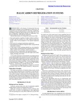
N the United States, almost 200 000 retail food stores operate
their refrigeration systems around the clock to ensure proper
merchandising and safety of their food products. Figure 1 shows
that supermarkets and convenience stores make the largest contribution to this total (Food Marketing Institute 2004). In U.S. retail
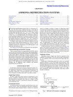
food stores, refrigeration consumes about 2.3% of the total electricity consumed by all commercial buildings (EIA 2003). As shown in
Figure 2, refrigeration accounts for roughly 50% of the electric
energy consumption of a typical supermarket (Arthur D. Little
1996). Supermarkets and grocery stores have one of the highest
electric usage intensities in commercial buildings, at 1650 MJ/m2
per year. Use for larger supermarkets with long operating hours has
been measured at 2710 MJ/m2 per year (Komor et al. 1998).
The modern retail food store is a high-volume sales outlet with
maximum inventory turnover. The Food Marketing Institute (2004)
defines a supermarket as any full-line self-service grocery store
with an annual sales volume of at least $2 million (Food Marketing
Institute 2004). These stores typically occupy approximately
Fig. 1
Distribution of Stores in Retail Food Sector
15.18
15.19
15.19
15.20
DISPLAY REFRIGERATORS
Fig. 1
Distribution of Stores in Retail Food Sector
Fig. 2 Percentage of Electric Energy Consumption,
by Use Category, of a Typical Large Supermarket
Fig. 2 Percentage of Electric Energy Consumption, by Use
Category, of Typical Large Supermarket
The preparation of this chapter is assigned to TC 10.7, Commercial Food
and Beverage Cooling, Display, and Storage.
Each category of perishable food has its own physical characteristics, handling logistics, and display requirements that dictate specialized display shapes and flexibility required for merchandising. Also,
the same food product requires different display treatment in different
locations, depending on local preferences, local income level, store
size, sales volume, and local availability of food items by type. Display refrigerators provide easy product access and viewing, and typically include additional lighting to highlight the product for sale.
Open display refrigerators for medium and low temperatures are
widely used in food markets. However, glass-door multideck models have also gained popularity. Decks are shelves, pans, or racks
that support the displayed product.
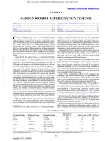
Medium- and low-temperature display refrigerator lineups account for roughly 68 and 32%, respectively, of a typical supermarket’s total display refrigerators (Figure 3). In addition, open vertical
meat, deli, and dairy refrigerators comprise about 46% of the total
display refrigerators (Faramarzi 2000).
Many operators combine single- and multideck models in most
departments where perishables are displayed and sold. Closedservice refrigerators are used to display unwrapped fresh meat,
15.1
Copyright © 2010, ASHRAE
This file is licensed to Abdual Hadi Nema (). License Date: 6/1/2010
15.2
2010 ASHRAE Handbook—Refrigeration (SI)
Fig. 3 Percentage Distribution of Display Refrigerators, by
Type,
in a Typical Supermarket
Fig. 3
Percentage Distribution of Display Refrigerators,
by Type, in Typical Supermarket
Fig. 4 Selected Temperatures in an Open Vertical Meat Display Refrigerator
Table 1 Air Temperatures in Display Refrigerators
Air Discharge Temperatures, °C a
Type of Fixture
Dairy
Multideck
Produce, packaged
Single-deck
Multideck
Meat, unwrapped (closed display)
Display area
Deli smoked meat
Multideck
Meat, wrapped (open display)
Single-deck
Multideck
Frozen food
Single-deck
Multideck, open
Glass door reach-in
Ice cream
Single-deck
Glass door reach-in
Minimum
Maximum
1.1
3.3
1.7
1.7
3.3
3.3
2.2b
3.3b
0
2.2
–4.5
–4.5
–3.3
–3.3
c
c
c
–25c
–23c
–20c
c
c
–31c
–25c
Licensed for single user. © 2010 ASHRAE, Inc.
a Air
temperatures measured with thermometer in outlet of refrigerated airstream and
not in contact with displayed product.
fresh meat should only be displayed in a closed, service-type display
refrigerator. Meat should be cooled to 2.2°C internal temperature before placing on
display. Refrigerator air temperature should be adjusted to keep internal meat temperature at 2.2°C or lower for minimum dehydration and optimum display life. Display
refrigerator air temperature varies with manufacturer.
cMinimum temperatures for frozen foods and ice cream are not critical (except for
energy conservation); maximum temperature is important for proper preservation of
product quality. Differences in display temperatures among the three different styles of
frozen food and ice cream display refrigerators are caused by orientation of refrigeration air curtain and size and style of opening. Single-deck refrigerators have a horizontal air curtain and opening of approximately 760 to 1070 mm. Multideck, open
refrigerators have a vertical air curtain and an opening of about 1070 to 1270 mm.
Glass door reach-in refrigerators have a vertical air curtain protected by a multiplepane insulated glass door.
b Unwrapped
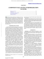
Fig. 4 Selected Temperatures in Open Vertical Meat Display
Refrigerator
delicatessen food, and, frequently, fish on crushed ice supplemented
by mechanical refrigeration. A store employee assists the customer
by obtaining product out of the service-type refrigerator. More complex layouts of display refrigerators have been developed as new or
remodeled stores strive to be distinctive and more attractive. Refrigerators are allocated in relation to expected sales volume in each
department. Thus, floor space is allocated to provide balanced
stocking of merchandise and smooth flow of traffic in relation to
expected peak volume periods.
Small stores accommodate a wide variety of merchandise in limited floor space. Thus, managers of these stores want to display more
quantity and variety of merchandise in the available floor space. The
concentration of large refrigeration loads in a small space makes
year-round space temperature and humidity control essential.
Product Temperatures
Display refrigerators are designed to merchandise food to maximum advantage while providing short-term storage. Proper maintenance of product temperature plays a critical role in food safety. An
estimated 24 to 81 million people annually become ill from microorganisms in food, resulting in an estimated 10 000 needless deaths
every year. As a result, in 1995 the Food and Drug Administration
(FDA) Food Code recommended a lower storage temperature for
certain refrigerated food products for further prevention of foodborne diseases. The FDA 2001 Food Code requires that the core
temperature of meat, poultry, fish, dairy, deli, and cut produce not
exceed 5°C throughout packaging, shipping, receiving, loading, and
storing (FDA 2001).
Proper maintenance of product temperature relies heavily on the
temperature of air discharged into the refrigerator. Table 1 lists discharge air temperatures in various display refrigerators, although
compliance with FDA requirements may require different refrigerator air temperatures. Figure 4 depicts a relationship between discharge air, return air, and average product temperatures for an open
vertical meat display refrigerator. These profiles were obtained
from controlled tests conducted over a 24 h period. Discharge and
return air temperatures were measured at the air grille. As shown, all
temperatures reach their peak at the end of each of four defrosts
(Faramarzi et al. 2001).
Product temperatures inside a display refrigerator may also vary,
depending on the location of the product. Figure 5 depicts product
temperature profiles and variations for an open vertical meat display
refrigerator over a period of 24 h. As shown, the lowest product temperatures are observed at the top shelf near the discharge air grille,
and the highest product temperatures are at the bottom shelf near the
return air grille (Gas Research Institute 2000).
Display refrigerators are not designed to cool the product; they
are designed to maintain product temperature. When put into the
refrigerator, merchandise should be at or near the proper temperature. Food placed directly into the refrigerator or into another
adequately refrigerated storage space on delivery to the store should
come from properly refrigerated trucks. Little or no delay in transferring perishables from storage or trucks to the display refrigerator
or storage space should be allowed.
Display refrigerators should be loaded properly. Most manufacturers provide indicators of physical load limits that define the
refrigerated zone. The product on display should never be loaded so
that it is out of the load limit zone or be stacked so that circulation
of refrigerated air is blocked. The load line recommendations of the
manufacturer must be followed to obtain good refrigeration performance. Proper refrigerator design and loading minimize energy use,
This file is licensed to Abdual Hadi Nema (). License Date: 6/1/2010
Retail Food Store Refrigeration and Equipment
15.3
Licensed for single user. © 2010 ASHRAE, Inc.
Fig. 5 Product Temperature Profiles at Four Different Locations Inside a Multideck Meat Refrigerator
(Average Discharge Air Temperature of )
Fig. 5 Product Temperature Profiles at Four Different Locations Inside Multideck Meat Refrigerator
(Average Discharge Air Temperature of –2°C)
Fig. 6 Comparison of Maximum Product Temperature Variations Under Different Improper Product Loading Scenarios in
an Open Vertical Meat Display Refrigerator
Table 2 Average Store Conditions in United States
Season
Winter
Spring
Summer
Fall
Dry-Bulb
Wet-Bulb
Grams
Temperature, Temperature,
Moisture per
°C
°C
Kilogram Dry Air
20.6
21.1
21.7
21.1
12.2
14.4
16.1
14.4
5.4
7.9
9.1
7.9
rh,
%
36
50
56
50
Store Conditions Survey conducted by Commercial Refrigerator Manufacturers’ Association from December 1965 to March 1967. About 2000 store readings in all parts of
the country, in all types of stores, during all months of the year reflected the above
ambient store conditions.
Fig. 6 Comparison of Maximum Product Temperature
Variations Under Different Improper Product Loading
Scenarios in Open Vertical Meat Display Refrigerator
maximize efficiency of the refrigeration equipment, maximize food
safety, and minimize product loss.
In actual applications, however, products may not always be
loaded properly. Survey results (Faramarzi 2003) reveal that
improper loading of products inside display refrigerators may fall
into the following categories:
• Blocked return air (products block the return air grille)
• Overloading (products loaded beyond the load limit zones)
• Cavities (products loaded nonuniformly, leaving empty spots or
voids on the shelves)
• Blocked air curtain (products suspended in the path of air curtain)
• Extreme (combination of blocked return air, blocked air curtain,
and overloading)
Improper loading of the products can significantly affect maximum product temperatures, which adversely affects food safety and
product loss. Figure 6 depicts the consequences of various improper
product-loading scenarios on maximum product temperature of an
open vertical meat display refrigerator (Faramarzi 2003).
Additionally, packaging may also affect food temperatures. The
surface temperature of a loosely wrapped package of meat with an
air space between the film and surface may be 1 to 2 K higher than
the surrounding air inside the display refrigerator.
Store Ambient Effect
Display fixture performance is affected significantly by the temperature, humidity, and movement of surrounding air. Display
refrigerators are designed primarily for supermarkets, virtually all
of which are air conditioned.
Table 2 summarizes a study of ambient conditions in retail food
stores. Individual store ambient readings showed that only 5% of all
readings (including those when the air conditioning was not operating) exceeded 24°C db or 10.2 g of moisture per kilogram of dry
air. Based on these data, the industry chose 24°C db and 18°C wb
(55% rh, 14.2°C dew point) as summer design conditions. This is
the ambient condition at which refrigeration load for food store display refrigerators is normally rated.
Store humidity is one of the most critical variables that can affect
performance of display refrigerators and refrigeration systems. Store
relative humidity may depend on climatic location, seasonal
changes, and, most importantly, on the store dehumidification or
HVAC system.
Figure 7 shows an example of the relationship between refrigerator condensate and relative humidity. The increase in frost
accumulation on the evaporator coils, and consequent increase in
This file is licensed to Abdual Hadi Nema (). License Date: 6/1/2010
15.4
2010 ASHRAE Handbook—Refrigeration (SI)
Fig. 7 Comparison of Collected Condensate vs. Relative
Humidity for Open Vertical Meat, Open Vertical
Dairy/Deli, Narrow Island Coffin, and Glass Door
Reach-In Display Refrigerators
Table 3
Relative Refrigeration Requirements with
Varying Store Ambient Conditions
21°C db
Refrigerator
Model
Multideck dairy
Multideck lowtemperature
Single-deck lowtemperature
Single-deck red
meat
Multideck red
meat
Low-temperature
reach-in
Fig. 7 Comparison of Collected Condensate vs. Relative
Humidity for Open Vertical Meat, Open Vertical Dairy/Deli,
Narrow Island Coffin, and Glass Door Reach-In
Display Refrigerators
26°C db
Relative Humidity, %
30
40
55
60
70
Relative Humidity, %
50
55
65
0.90 0.95 1.00 1.08a 1.18b
0.90 0.95 1.00 1.08a 1.18b
0.99
0.99
1.08a
1.08a
1.18b
1.18b
0.90 0.95 1.00 1.08a 1.15
0.99
1.05
1.15
0.90 0.95 1.00 1.08a 1.15
0.99
1.05
1.15
0.90 0.95 1.00 1.08a 1.18b
0.99
1.08a
1.18b
0.90 0.95 1.00 1.05a 1.10
0.99
1.05a
1.10
Note: Package warm-up may be more than indicated. Standard flood lamps are clear
PAR 38 and R-40 types.
a More frequent defrosts required.
b More frequent defrosts required plus internal condensation (not recommended).
Licensed for single user. © 2010 ASHRAE, Inc.
(Gas Research Institute 2000)
Fig. 8 Percentage of Latent Load to Total Cooling Load at Different Indoor Relative Humidities
Fig. 8
Percentage of Latent Load to Total Cooling Load at
Different Indoor Relative Humidities
(Gas Research Institute 2000)
condensate weight, is more drastic for open vertical display refrigerators. In other words, open vertical fixtures demonstrate
more vulnerability to humidity variations and remove more moisture from the ambient (or store) air than other types of display refrigerators (Gas Research Institute 2000).
Increased frost formation from higher relative humidities increases latent load, which the refrigeration system must remove
(Figure 8). Additional defrosts may be needed to maintain the product at its desired temperature.
When store ambient relative humidity is different from that at
which the refrigerators were rated, the energy requirements for
refrigerator operation will vary. Howell (1993a, 1993b) concludes
that, compared to operation at 55% store rh, display refrigerator
energy savings at 35% rh range from 5% for glass door reach-in
refrigerators to 29% for multideck deli refrigerators. Table 3 lists
correction factors for the effect of store relative humidity on display refrigerator refrigeration requirements when the dry-bulb
temperature is 21 and 26°C.
Manufacturers sometimes publish ratings for open refrigerators
at lower ambient conditions than the standard because the milder
conditions may significantly reduce the cooling load on the refrigerators. In addition, lower ambient conditions may allow both
reductions in antisweat heaters and fewer defrosts, allowing substantial energy savings on a storewide basis.
The application engineer needs to verify that the year-round store
ambient conditions are within the performance ratings of the various refrigerators selected for the store. Because relative humidity
varies throughout the year, the dew point for each period should be
analyzed. The sum of these refrigerator energy requirements provides the total annual energy consumption. In a store designed for a
maximum relative humidity of 55%, the air-conditioning system
will dehumidify only when the relative humidity exceeds 55%.
In climates where the outdoor air temperature is low in winter, infiltration of outdoor air and mechanical ventilation can cause store
humidity to drop below 55% rh. Separate calculations need to be
done for periods during which mechanical dehumidification is used
and periods when it is not required. For example, in Boston, Massachusetts, mechanical dehumidification is required for only about
3 1/2 months of the year, whereas in Jacksonville, Florida, it is
required for almost 7 1/2 months of the year. Also, in Boston, there
are 8 1/2 months when the store relative humidity is below 40%,
whereas Jacksonville has these conditions for only 4 1/2 months. The
engineer must weigh the savings at lower relative humidity against
the cost of the mechanical equipment required to maintain relative
store humidity levels at, for example, below 40% instead of 55%.
Additional savings can be achieved by controlling antisweat
heaters and reducing defrost frequency at ambient relative humidities below 55%. Energy savings credit for reduced use of display
refrigerator antisweat heaters can only be taken if the display refrigerators are equipped with humidity-sensing controls that reduce the
amount of power supplied to the heaters as the store dew point
decreases. Also, defrost savings can be considered when defrost frequency or duration is reduced. Controls can reduce the frequency of
defrost as store relative humidity decreases (demand defrost). Individual manufacturers give specific antisweat and defrost values for
their equipment at stated store conditions. Less defrosting is needed
as store dew point temperature or humidity decreases from the
design conditions.
Attention should also be given to the condition in which store drybulb temperatures are higher than the industry standard, because this
raises the refrigeration requirements and consequently the energy
demand.
Display Refrigerator Cooling Load and Heat Sources
Heat transfer in a display refrigerator involves interactions between the product and the internal environment of the refrigerator,
as well as heat from the surroundings that enters the refrigerator.
This file is licensed to Abdual Hadi Nema (). License Date: 6/1/2010
Licensed for single user. © 2010 ASHRAE, Inc.
Retail Food Store Refrigeration and Equipment
Heat components from the surrounding environment include transmission (or conduction), radiation, and infiltration, whereas heat
components from the internal environment include lights and evaporator fan motor(s). In addition, defrost and antisweat heaters also
increase the cooling load of a display refrigerator. Conduction,
radiation, and infiltration loads from the surroundings into the refrigerator, as well as heat exchanges between the product and parts
of the refrigerator, depend on the temperatures of ambient air and air
within the refrigerator. Open vertical display refrigerators rely on
their air curtains to keep warm ambient air from penetrating into the
cold environment inside the refrigerator. An air curtain consists of a
stream of air discharged from a series of small nozzles through a
honeycombed baffle at the top of the display refrigerator. Air curtains play a significant role in the thermal interaction of the display
refrigerator with the surrounding air (see Figure 10).
The cooling load of a typical display refrigerator has both sensible and latent components. In general, the sensible portion consists
of heat gain from lights, fan motor(s), defrost (electric and hot gas),
antisweat heater, conduction, radiation, infiltration, and product
pulldown load. The latent portion consists of infiltration and product latent heat of respiration.
Conduction Load. The conduction load refers to the heat transmission through the physical envelope of the display refrigerator.
The temperature difference between air in the room and air inside the
refrigerator is the main driving force for this heat transfer.
Radiation Load. The heat gain of the display refrigerator through
radiation is a function of conditions inside the refrigerator, including surface temperature, surface emissivity, surface area, view factor with respect to the surrounding (store) walls/objects, floor,
ceiling, and their corresponding emissivities and areas.
Infiltration Load. The infiltration load of the display refrigerator refers to the net entrainment of warm, moist air through the air
curtain into the refrigerated space. The infiltration load has two
components: sensible and latent. The total performance of the air
curtain and the amount of heat transferred across it may depend on
several factors, including
•
•
•
•
•
•
•
Air curtain velocity and temperature profile
Number of jets
Air jet width and thickness
Dimensional characteristics of the discharge air honeycomb
Store and display refrigerator temperatures and humidity ratios
Rate of air curtain agitation caused by shoppers passing
Thermo-fluid boundary condition in the initial region of the jet
Sensible Infiltration. The sensible portion of infiltration refers
to the direct heat added by the temperature difference between cold
air in the refrigerator and warm room air drawn into the refrigerator.
Latent Infiltration. The latent portion of infiltration refers to the
heat content of the moisture added to the refrigerator by the room air
drawn into the refrigerator.
Internal Loads. The internal load includes heat from refrigerator
lights and evaporator fan motors. The lamps, ballasts, and fan motors
are typically located within the thermodynamic boundary of the display refrigerator; therefore, their total heat dissipation should be considered part of the refrigerator load. High-intensity lighting raises
product temperatures and can discolor meats. Refrigerator shelf ballasts are sometimes located out of the refrigerated space to reduce
refrigerator cooling load. Standard lighting equipment, which typically consists of T12 fluorescent lamps with magnetic ballast, draws
approximately 0.73 A at 120 V.
Defrost Load. Refrigeration equipment in applications where
frost can accumulate on the evaporator coils have some type of
defrost mechanism. During defrost, refrigeration is stopped on the
defrosting circuits and heat is introduced into the refrigerator.
Defrost methods vary, depending on the refrigeration application
and storage temperatures, as discussed in the section on Methods of
Defrost. Some defrost methods deliver more heat than is needed to
15.5
melt the ice. A large portion of the extra heat warms the coil metal,
product (see Figures 4 and 5), and refrigerator. This extra heat adds
to the refrigeration load and is called the postdefrost pulldown load
(Faramarzi 1999).
Antisweat Heaters (ASH) Load. The antisweat heater load refers to the portion of the electrical load of the ASH that ends up as
sensible heat inside the refrigerator. Antisweat heaters are used on
most low-temperature open display refrigerators, as well as reach-in
refrigerators with glass doors. These electric resistance heaters are
located around the handrails of tub refrigerators and door frame/
mullions of reach-in refrigerators to prevent condensation on metal
surfaces. They also reduce fogging of the glass doors of reach-in
refrigerators, a phenomenon that can hurt product merchandising.
Without appropriate control systems, ASH units stay on round the
clock. The cooling load contribution of ASH in a typical reach-in
display refrigerator can reach 35% of their connected electric load
(Faramarzi et al. 2001).
Pulldown Load. The pulldown load has two components (Faramarzi 1999):
• Case product load. This pulldown load is caused by product delivery into the refrigerator at a temperature higher than the designated storage temperature. It is the amount of cooling required to
lower the product temperature to a desired target temperature.
• Postdefrost load. During the defrost cycle, product temperature
inside the refrigerator rises. Once defrost is complete, the refrigeration system turns on and must remove the accumulated defrost
heat and lower the product temperature to a desirable set point.
According to a test report by Gas Research Institute (2000), the
major contributor to the total cooling load of open display refrigerators are infiltration and radiation (Figure 9). Infiltration constitutes
approximately 80% of the cooling load of a typical mediumtemperature open vertical display refrigerator. The relative role of
infiltration diminishes for low-temperature open coffin (or tub) refrigerators, and is supplanted by radiation. Infiltration and radiation
constitute roughly 24 and 43%, respectively, of the cooling load of
a typical open coffin refrigerator.
Multideck open refrigerator shelves are an integral part of the air
curtain and airstream. Without shelves, there will be substantial air
distribution problems. An air deflector may be required when shelves
are removed. As shown in Figure 9, infiltration through the air curtain
plays a significant role in the cooling load of open vertical display
refrigerators (Faramarzi 1999). Figure 10 depicts the air curtain
velocity streamlines of an 2.4 m open vertical meat display refrigerator. These velocity streamlines represent the actual airflow patterns
using digital particle image velocimetry. As shown, warm air is
Fig. 9 Components of Refrigeration Load for Several Display
Refrigerator Designs at 24°C Dry Bulb and 55% Relative
Humidity
Fig. 9 Components of Refrigeration Load for Several Display
Refrigerator Designs at 24°C db and 55% rh
This file is licensed to Abdual Hadi Nema (). License Date: 6/1/2010
15.6
Fig. 10 Velocity Streamlines of a Single-Band Air Curtain in
an Open Vertical Meat Display Refrigerator, Captured Using
Digital Particle Image Velocimetry Technique
2010 ASHRAE Handbook—Refrigeration (SI)
temperatures above the dew point. However, when no other technique is known, resistance heating becomes necessary. Control by
cycling and/or proportional controllers to vary heat with store ambient changes can reduce energy consumption.
Store designers can do a great deal to promote energy efficiency.
Not only does controlling the atmosphere within a store reduce
refrigeration requirements, it also reduces the need to heat the surfaces of refrigerators. This heat not only consumes energy, but also
places added demand on the refrigeration load.
Evaporators and air distribution systems for display refrigerators
are highly specialized and are usually fitted precisely into the particular display refrigerator. As a result, they are inherent in the fixture and are not standard independent evaporators. The design of the
air circuit system, the evaporator, and the means of defrosting are
the result of extensive testing to produce the particular display
results desired.
Licensed for single user. © 2010 ASHRAE, Inc.
Cleaning and Sanitizing Equipment
Because the evaporator coil is the most difficult part to clean,
consider the judicious use of high-pressure, low-liquid-volume sanitizing equipment. This type of equipment enables personnel to
spray cleaning and sanitizing solutions into the duct, grille, coil, and
waste outlet areas with minimum disassembly and maximum effectiveness. However, this equipment must be used carefully because
the high-pressure stream can easily displace sealing and caulking
materials. High-pressure streams should not be directed toward
electrical devices. Hot liquid can also break the glass on models
with glass fronts and on closed-service fixtures.
Refrigeration Systems for Display Refrigerators
Fig. 10 Velocity Streamlines of Single-Band Air Curtain in
Open Vertical Meat Display Refrigerator, Captured Using
Digital Particle Image Velocimetry Technique
entrained into the display refrigerator at several locations along the
plane of the air curtain. Based on the law of conservation of mass, an
equal (and substantial) amount of cold air from the display refrigerator spills into the room near the return air grille of the fixture.
Refrigerator Construction
Commercial refrigerators for market installations are usually of
the endless construction type, which allows a continuous display as
refrigerators are joined. Clear plastic panels are often used to separate refrigerator interiors when adjacent refrigerators are connected
to different refrigeration circuits. Separate end sections are provided for the first and last units in a continuous display. Methods of
joining self-service refrigerators vary, but they are usually bolted or
cam-locked together.
All refrigerators are constructed with surface zones of transition
between the refrigerated area and the room atmosphere. Thermal
breaks of various designs separate the zones to minimize the amount
of refrigerator surface that is below the dew point. Surfaces that may
be below the dew point include (1) in front of discharge air nozzles,
(2) the nose of the shelving, and (3) front rails or center flue of the
refrigerator. In glass door reach-in freezers or medium-temperature
refrigerators, the frame jambs and glass can be below the dew point.
In these locations, resistance heat is used effectively to raise the
exterior surface temperature above the dew point to prevent accumulation of condensation.
With the current emphasis on energy efficiency, designers have
developed means other than resistance heat to raise the surface
Self-Contained. Self-contained systems, in which the condensing unit and controls are built into the refrigerator structure,
are usually air-cooled and are of two general types. The first type
has the condensing unit beneath the cabinet; in some designs, it
takes up the entire lower part of the refrigerator, but in others it
occupies only one lower corner. The second type has the condensing unit on top.
Remote. Remote refrigeration systems are often used if cabinets are installed in a hot or otherwise unfavorable location where
the noise or heat of the condensing units would be objectionable.
Remote systems can take advantage of cool ambient air and provide lower condensing temperatures, which allows more efficient
operation of the refrigeration system.
Merchandising Applications
Dairy Display. Dairy products include items with significant
sales volume, such as fresh milk, butter, eggs, and margarine. They
also include a myriad of small items such as fresh (and sometimes
processed) cheeses, special above-freezing pastries, and other perishables. Available display equipment includes the following:
• Full-height, fully adjustable shelved display units without doors
in back for use against a wall (Figure 11); or with doors in back
for rear service or for service from the rear through a dairy cooler.
The effect of rear service openings on the surrounding refrigeration must be considered. The front of the refrigerator may be open
or have glass doors.
• Closed-door displays built in the wall of a walk-in cooler with
adjustable shelving behind doors. Shelves are located and stocked
in the cooler (Figure 12).
• A variety of other special display units, including single-deck and
island-type display units, some of which are self-contained and
reasonably portable for seasonal, perishable specialties.
• A refrigerator, similar to that in Figure 11, but able to receive either
conventional shelves and a base shelf and front or premade displays on pallets or carts. This version comes with either front-load
This file is licensed to Abdual Hadi Nema (). License Date: 6/1/2010
Retail Food Store Refrigeration and Equipment
capability only or rear-load capability only (Figure 13). These are
called front roll-in or rear roll-in display refrigerators.
Meat Display. Most meat is sold prepackaged. Some of this
product is cut and packaged on the store premises. Control of
temperature, time, and sanitation from the truck to the checkout
counter is important. Meat surface temperatures over 4.5°C shorten
its salable life significantly and increase the rate of discoloration.
The design of open fresh meat display refrigerators, either tubtype single-deck or vertical multideck, is limited by the freezing
point of meat. Ideally, refrigerators are set to operate as cold as possible without freezing the meat. Temperatures are maintained with
Fig. 11 Multideck Dairy Display Refrigerator
15.7
minimal fluctuations (with the exception of defrost) to ensure the
coldest possible stable internal and surface meat temperatures.
Sanitation is also important. If all else is kept equal, good sanitation can increase the salable life of meat in a display refrigerator.
In this chapter, sanitation includes limiting the amount of time meat
is exposed to temperatures above 4.5°C. If meat has been handled in
a sanitary manner before being placed in the display refrigerator,
elevated temperatures can be more tolerable. When meat surfaces
are contaminated by dirty knives, meat saws, table tops, etc., even
optimum display temperatures will not prevent premature discoloration and subsequent deterioration of the meat. See the section on
Meat Processing Rooms for information about the refrigeration
requirements of the meat-wrapping area.
Along with molds and natural chemical changes, bacteria discolor meat. With good control of sanitation and refrigeration, experiments in stores have produced meat shelf life of one week and
more. Bacterial population is greatest on the exposed surface of displayed meat because the surface is warmer than the interior.
Although cold airflow refrigerates each package, the surface temperature (and thus bacterial growth) is cumulatively increased by
Licensed for single user. © 2010 ASHRAE, Inc.
•
•
•
•
•
Infrared rays from lights
Infrared rays from the ceiling surface
High stacking of meat products
Voids in display
Store drafts that disturb refrigerator air
Improper control of these factors may cause meat surface temperatures to rise above values allowed by food-handling codes. It
takes great care in every building and equipment detail, as well as in
refrigerator loading, to maintain meat surface temperature below
4.5°C. However, the required diligence is rewarded by excellent
shelf life, improved product integrity, higher sales volume, and less
scrap or spoilage.
Surface temperatures rise during defrost. Tests have compared
matched samples of meat: one goes through normal defrost, and the
other is removed from the refrigerator during its defrosting cycles.
Fig. 13 Vertical Rear-Load Dairy (or Produce)
Refrigerator with Roll-In Capability
Fig. 11 Multideck Dairy Display Refrigerator
Fig. 12 Typical Walk-In Cooler Installation
Fig. 12 Typical Walk-In Cooler Installation
Fig. 13 Vertical Rear-Load Dairy (or Produce)
Refrigerator with Roll-In Capability
This file is licensed to Abdual Hadi Nema (). License Date: 6/1/2010
15.8
2010 ASHRAE Handbook—Refrigeration (SI)
Although defrosting characteristics of refrigerators vary, such tests
have shown that the effects on shelf life of properly handled defrosts
are negligible. Tests for a given installation can easily be run to prove
the effects of defrosting on shelf life for that specific set of conditions.
Self-Service Meat Refrigerators. Self-service meat products are
displayed in packaged form. Processed meat can be displayed in
similar refrigerators as fresh packaged meat, but at slightly higher
temperatures. The meat department planner can select from a wide
variety of available meat display possibilities:
• Single-deck refrigerators, with optional rear or front access storage doors (Figure 14)
• Multideck refrigerators, with optional rear access (Figure 15)
• Either of the preceding, with optional glass fronts
All these refrigerators are available with a variety of lighting,
superstructures, shelving, and other accessories tailored to special
merchandising needs. Storage compartments are rarely used in selfservice meat refrigerators.
Licensed for single user. © 2010 ASHRAE, Inc.
Fig. 14 Single-Deck Meat Display Refrigerator
Closed-Service Meat or Deli Refrigerators. Service meat products are generally displayed in bulk, unwrapped. Generally, closed
refrigerators can be grouped in one of the following categories:
• Fresh red meat, with optional storage compartment (Figure 16)
• Deli and smoked or processed meats, with optional storage
• Fresh fish and poultry, usually without storage but designed to
display products on a bed of cracked ice
Closed-service meat display refrigerators are offered in a variety
of configurations. Their fronts may be nearly vertical or angled up
to 20° from vertical in flat or curved glass panels, either fixed or
hinged, and they are available with gravity or forced-convection
coils. Gravity coils are usually preferred for more critical products,
but forced-air coil models using various forms of humidification
systems are also common.
These service refrigerators typically have sliding rear access
doors, which are sometimes removed during busy periods. This
practice is not recommended by manufacturers, however, because it
affects the internal product display zone temperature and humidity.
Produce Display. Wrapped and unwrapped produce is often
intermixed in the same display refrigerator. Ideally, unwrapped produce should have low-velocity refrigerated air forced up through the
loose product. Water is usually also sprayed, either by manually
operated spray hoses or by automatic misting systems, on leafy vegetables to retain their crispness and freshness. Produce is often displayed on a bed of ice for visual appeal. However, packaging
prevents air from circulating through wrapped produce and requires
higher-velocity air. Equipment available for displaying both packaged and unpackaged produce is usually a compromise between
these two desired features and is suitable for both types of product.
Available equipment includes the following:
• Wide or narrow single-deck display units with or without mirrored superstructures.
• Two- or three-deck display units, similar to the one in Figure 17,
usually for multiple-refrigerator lineups near single-deck display
refrigerators.
• Because of the nature of produce merchandising, a variety of nonrefrigerated display units of the same family design are usually
designed for connection in continuous lineup with the refrigerators.
Fig. 14 Single-Deck Meat Display Refrigerator
Fig. 15 Multideck Meat Refrigerator
Fig. 15 Multideck Meat Refrigerator
Fig. 16 Closed-Service Display Refrigerator
(Gravity Coil Model with Curved Front Glass)
Fig. 16 Closed-Service Display Refrigerator
(Gravity Coil Model with Curved Front Glass)
This file is licensed to Abdual Hadi Nema (). License Date: 6/1/2010
Retail Food Store Refrigeration and Equipment
• A refrigerator, similar to that in Figure 17, but able to receive
either conventional shelves and a base shelf and front or premade
displays on pallets and carts. This version comes with either
front-load or rear-load capability (see Figure 13).
Produce equipment is generally available with a variety of merchandising and other accessories, including bag compartments,
sprayers for wetting the produce, night covers, scale racks, sliding
mirrors, and other display shelving and apparatus.
Frozen Food and Ice Cream Display
To display frozen foods most effectively (depending on varied
need), many types of display refrigerators have been designed and
are available. These include the following:
Licensed for single user. © 2010 ASHRAE, Inc.
• Single-deck tub-type refrigerators for one-side shopping (Figure
18). Many types of merchandising superstructures for related
nonrefrigerated foods are available. Configurations are designed
for matching lineup with fresh meat refrigerators, and there are
similar refrigerators for matching lineup of ice cream refrigerators with their frozen food counterparts. These refrigerators are
offered with or without glass fronts.
15.9
• Single-deck island for shop-around (Figure 19). These are available in widths ranging from the single-deck refrigerators in Item
1 to refrigerators of double width, with various sizes in between.
Some across-the-end increments are available with or without
various merchandising superstructures for selling related nonrefrigerated food items to complete the shop-around configuration.
• Freezer shelving in two to six levels with many refrigeration system configurations (Figure 20). Multideck self-service frozen
food and ice cream fixtures are generally more complex in design
and construction than single-deck models. Because they have
wide, vertical display compartments, they are more affected by
ambient conditions in the store. Generally, open multideck models have two or three air curtains to maintain product temperature
and shelf life requirements.
Fig. 19 Single-Deck Island Frozen Food Refrigerator
Fig. 17 Multideck Produce Refrigerator
Fig. 19 Single-Deck Island Frozen Food Refrigerator
Fig. 20 Multideck Frozen Food Refrigerator
Fig. 17
Multideck Produce Refrigerator
Fig. 18 Single-Deck Well-Type Frozen Food Refrigerator
Fig. 18 Single-Deck Tub-Type Frozen Food Refrigerator
Fig. 20 Multideck Frozen Food Refrigerator
This file is licensed to Abdual Hadi Nema (). License Date: 6/1/2010
15.10
2010 ASHRAE Handbook—Refrigeration (SI)
• Glass door, front reach-in refrigerators (Figure 21), usually of a
continuous lineup design. This style allows for maximum inventory volume and variety in minimum floor space. The frontto-back interior dimension of these cabinets is usually about
600 mm. Greater attention must be given to the back product to
provide the desired rotation. Although these refrigerators generally consume less energy than open multideck low-temperature
refrigerators, specific comparisons by model should be made to
determine capital and operating costs.
• Spot merchandising refrigerators, usually self-contained and
sometimes arranged for quick change from nonfreezing to freezing temperature to allow for promotional items of either type
(e.g., fresh asparagus or ice cream).
• Versions of most of the above items for ice cream, usually with
modified defrost heaters and other changes necessary for the
approximately 5.5 K colder required temperature. As display
temperature decreases to below –18°C (product temperature), the
problem of frost and ice accumulation in flues and in the product
zone increases dramatically. Proper product rotation and frequent
restocking minimize frost accumulation.
Licensed for single user. © 2010 ASHRAE, Inc.
Energy Efficiency Opportunities in Display
Refrigerators
Energy efficiency of display refrigerators can be improved by
carefully selecting components and operating practices. Typically,
efficiency is increased through one or more of the methods discussed in this section. Different products use different components
and design strategies. Some of the following options are mature
and tested in the industry, whereas others are emerging technologies. Designers must balance energy savings against customer
requirements, manufacturing cost, system performance, reliability, and maintenance costs.
Cooling Load Reduction. Cooling load reduction is the first
step to take when attempting to increase refrigeration equipment
efficiency. Reducing the amount of heat that must be removed from
a space leads to instant savings in energy consumption. Display
refrigerators should be located to minimize drafts or air curtain disturbance from ventilation ducts, and away from heat sources or
Fig. 21 Glass Door, Frozen Food Reach-In Refrigerator
Fig. 21
Glass Door, Medium-Temperature and Frozen Food
Reach-In Refrigerator
direct sunlight. Cooling load of a typical refrigerator is dependent
on infiltration, conduction, and radiation from surroundings, as well
as heat dissipation from internal components.
Infiltration. Research indicates that infiltration of warm and
moist air from the sales area into an open vertical display refrigerator accounts for 70 to 80% of the display refrigerator total cooling
load (Faramarzi 1999). Infiltrated air not only raises product temperatures, but moisture in the air also becomes frost on the evaporator coil, reducing its heat transfer abilities and forcing the fan to
work harder to circulate air through the refrigerator. There are several ways to reduce the amount of infiltration into refrigerators:
• Installing glass doors on open vertical display refrigerators
provides a permanent barrier against infiltration. Similarly, vertical refrigerators with factory-installed doors eliminate most infiltration and significantly reduce cooling load.
• Optimizing the air curtain can drastically reduce its entrainment
of ambient air. This ensures that a larger portion of cold air supplied by the refrigerator makes it back to the evaporator through
the return air duct.
• In stores that do not operate 24 h per day, installing night covers
can provide an infiltration barrier during unoccupied hours. Faramarzi (1997) found that 6 h of night cover use can reduce the
cooling load by 8% and the compressor power requirement by
9%. Select night curtains that do not condense water on the outside, creating potential for slippery floors. Also, consult local
health inspectors to ensure that the curtain is considered cleanable
and acceptable for use in a grocery store.
Thermal Radiation. Warm objects near the display refrigerator
radiate heat into the refrigerated space. Night covers protect against
radiation heat transfer.
Thermal Conduction. Improving the R-value of insulation,
whether by using materials with low thermal conductivity or simply
increasing insulation thickness, reduces conduction heat transfer
through walls of the refrigerated space. Conduction accounts for
less than 5% of cooling load of medium-temperature refrigerators
but almost 20% for low-temperature refrigerators (see Figure 9).
Display Refrigerator Component Improvements. Careful selection of components based on proper application, energy efficiency
attributes, and correct sizing can play a significant role in increasing
overall system efficiency.
Evaporator. Evaporator coil design can significantly affect refrigerator performance. Efficient evaporator coils allow the refrigerator
to maintain its target discharge air temperature while operating at a
higher evaporator temperature. Higher evaporator temperature (or
suction pressure) has the benefit of increasing its refrigeration effect;
however, it also hampers refrigeration system performance by increasing the density of refrigerant entering the compressor, thus
increasing compressor work. Evaporator coil characteristics can be
improved in four ways:
• Increased heat transfer effectiveness. Efficient coils have a
greater heat transfer surface area made of materials with improved heat transfer properties to absorb as much heat from the air
as possible using optimized fin design. Evaporator fans should
also be selected to evenly distribute air through the maximum
possible coil face area.
• Improved coil tube design: low friction and high conduction.
Materials used to construct coils, such as copper, have increased
conductivity, which allows heat to transfer through the coil materials more easily. Enhancements to the inside surface of coil tubes
can assist heat transfer from the coil material to the refrigerant by
creating turbulence in the refrigerant, thereby increasing its contact time with the tube surface. However, use caution when
designing these features, because excessive turbulence can cause
a pressure drop in the refrigerant and force the compressor to
This file is licensed to Abdual Hadi Nema (). License Date: 6/1/2010
Retail Food Store Refrigeration and Equipment
Licensed for single user. © 2010 ASHRAE, Inc.
work harder, negating any savings resulting from the enhancement (Dossat 1997).
• Improved refrigerant distribution. Coil performance depends
on the refrigerant’s path through the evaporator coil. For optimal
coil design, the coldest refrigerant should come into contact with
the coldest air to ensure maximum heat transfer capability.
• Frost-tolerant surface. Typically, the leading edge of the coil
shows the worst frosting because moisture in return air condenses
as soon as it hits the cold surface. This frost can grow to the point
that it severely restricts airflow through the coil. Coils can be
manufactured from modules with different fin spacing so that
frost formation is controlled. Larger fin spacing on the leading
edge allows moisture to be removed and frost to build, but prevents the coil from becoming totally clogged. Smaller fin spacing
can be used toward the trailing edge to maximize heat transfer to
lower the air temperature to required levels.
Defrost. Heat added while the refrigeration system is in defrost
can raise product temperatures and must be removed later. Defrost
methods should be chosen so that the minimum amount of heat is
added to the refrigerator. For example, hot-gas defrost can be considered an improved technique.
Demand defrost technologies can sense frost formation on the
coil, enabling a controller to determine exactly when the refrigerator
should begin its defrost cycle. Unnecessary defrosts and excessive
frost formation leading to coil blockage can be eliminated. Care
must be used when selecting a demand defrost system: if the system
malfunctions, the refrigerators will require service, and there is the
potential for product loss.
Sensors may also be used to verify the end of defrost cycles (intelligent defrost termination). Typically, the refrigerator is allowed to
defrost for a set amount of time or until the air temperature leaving
the coil reaches a specified level. This usually means that the defrost
cycle is running for longer than necessary, allowing more heat to
enter the refrigerator and raise product temperatures. Intelligent
defrost termination sensors can determine exactly when the coil is
free of frost and immediately restart the refrigeration system. An
intelligent defrost termination sensor can be a simple electromechanical thermostat, a solid-state sensor, or other device.
Antisweat. Antisweat heaters (ASHs) with a low watt-per-door
rating should be used whenever possible. In addition to using less
energy at the antisweat heater level, less heat will be introduced into
the refrigerated space, thus indirectly reducing the cooling load.
Some controllers can recognize the antisweat heat needs of the
door and ensure that the heaters only operate when needed. They
adjust their operation accordingly, through pulsation or other mechanisms. Condensate sensors on reach-in glass doors activate ASHs
when droplets are detected; RH-based controllers sense the psychrometric properties of air and activate ASHs when needed.
New methods of glass door construction have brought products
that require little or no antisweat heat to maintain customer-friendly
fog-free panes. This performance is achieved by either using
advanced glass types or special door frames, both of which greatly
reduce or eliminate the amount of glass heating necessary to resist
condensation.
Alternative Expansion Valves. Dual-port thermostatic expansion valves (TXVs) have capacity modulation capabilities not seen
in other expansion valves. When the refrigerator emerges from
defrost, there is typically a much higher load because of increased
product temperatures. In this case, the large port of the expansion
valve opens, allowing the system to operate at a higher capacity to
account for the increased pulldown load.
Superheat can be most easily controlled by electronic expansion
valves, which have a much faster response time than bulb-sensing
TXVs. Manufacturers should test the valve and controller to ensure
it maintains stable control at targeted superheats.
15.11
Fig. 22 External Liquid-Suction Heat Exchanger
Fig. 22 External Liquid-to-Suction Heat Exchanger
(Walker 1992)
Liquid-to-Suction Heat Exchanger. Liquid-to-suction heat exchangers allow suction gas exiting the display refrigerator to absorb
heat from liquid refrigerant entering the display refrigerator, increasing the cooling capacity of the refrigerant (Figure 22). These
devices are most effective for low- and very-low-temperature applications (Walker 1992). The effectiveness of liquid-to-suction heat
exchangers also depends on which refrigerant is chosen. The system
designer must be cautious in choosing when to use a liquid-tosuction heat exchanger (Klein et al. 2000).
Sophisticated Refrigerator Controls. All components of a display refrigerator should be linked to one master control system,
which can optimally control the operation of individual components.
Power-Reducing Measures. Reducing power use of individual
components will result in energy savings over time, and can also
reduce the cooling load for components located inside the refrigerated space.
Energy-efficient evaporator fan motors such as electronically
commutated motors (ECMs) and permanent split capacitor (PSC)
motors consume about half the power of standard shaded-pole
motors (Faramarzi and Kemp 1999). These motors, located inside
the refrigerated space, produce less heat, thereby reducing the load
on the refrigeration equipment. These motors also can incorporate
variable-speed controls to slow fans as the cooling load is satisfied.
Standard lighting equipment, which typically consists of T12
fluorescent lamps with magnetic ballast, draws about 0.73 A at
120 V. More efficient lamps (T8 fluorescent lamps with electronic
ballast) draw only 0.49 A at 120 V. As a result, they introduce less
heat into the refrigerated space, which in turn reduces the refrigerator cooling load and improves maintenance of target product temperature without sacrificing light quality.
REFRIGERATED STORAGE ROOMS
Meat Processing Rooms
In a self-service meat market, cutting, wrapping, sealing, weighing, and labeling operations involve precise production control and
scheduling to meet varying sales demands. The faster the processing, the less critical the temperature and corresponding refrigeration
demand.
The wrapping room should not be too dry, but condensation on
the meat, which provides a medium for bacterial growth, should be
avoided by maintaining a dew-point temperature within a few degrees of the sensible temperature. Fan-coil units should be selected
with a maximum of 6 K temperature difference (TD) between the
entering air and the evaporator temperature. Low-velocity fan-coil
units are generally used to reduce the drying effect on exposed meat.
Gravity coils are also available and have the advantage of lower
room air velocities.
The meat wrapping area is generally cooled to about 7 to 13°C,
which is desirable for workers but not low enough for meat storage.
Thus, meat should be held in that room only for cutting and packaging; then, as soon as possible, it should be moved to a packaged
product storage cooler held at –2 to 0°C. The meat wrapping room
may be a refrigerated room adjacent to the meat storage cooler or
one compartment of a two-compartment cooler. In such a cooler,
one compartment is refrigerated at about –2 to 0°C and used as a
This file is licensed to Abdual Hadi Nema (). License Date: 6/1/2010
15.12
meat storage cooler, and the second compartment is refrigerated at
7 to 13°C and used as a cutting and packaging room. Best results are
attained when meat is cut and wrapped to minimize exposure to
temperatures above –2 to 0°C.
Licensed for single user. © 2010 ASHRAE, Inc.
Wrapped Meat Storage
At some point between the wrapping room and display refrigerator, refrigerated storage for the wrapped cuts of meat must be provided. Without this space, a balance cannot be maintained between
the cutting/packaging rate and the selling rate for each particular cut
of meat. Display refrigerators with refrigerated bottom storage compartments, equipped with racks for holding trays of meats, offer one
solution to this problem. However, the amount of stored meat is not
visible, and the inventory cannot be controlled at a glance.
A second option is a pass-through, reach-in cabinet. This cabinet
has both front and rear insulated glass doors and is located between
the wrapping room and the display refrigerators. After wrapping, the
meats are passed into the cabinet for temporary storage at –2 to 0°C
and then are withdrawn from the other side for restocking the display
refrigerator. Because these pass-through cabinets have glass doors,
the inventory of wrapped meats is visible and therefore controllable.
The third and most common option involves a section of the back
room walk-in meat storage cooler or a completely separate packaged meat storage cooler. The cooler is usually equipped with rolling racks holding slide-in trays of meat. This method also offers
visible inventory control and provides convenient access to both the
wrapping room and the display refrigerators.
The overriding philosophy in successful meat wrapping and merchandising can be summarized thus: keep it clean, keep it cold, and
keep it moving.
Walk-In Coolers and Freezers
Each category of displayed food product that requires refrigeration for preservation is usually backed up by storage in the back
room. This storage usually consists of refrigerated rooms with sectional walls and ceilings equipped with the necessary storage racks
for a particular food product. Walk-in coolers are required for storage of meat, some fresh produce, dairy products, frozen food, and
ice cream. Medium and large stores have separate produce and dairy
coolers, usually in the 2 to 4°C range. Meat coolers are used in all
food stores, with storage conditions between –2 and 0°C. Unwrapped meat, fish, and poultry should each be stored in separate
coolers to prevent odor transfer. Walk-in coolers, which serve the
dual purpose of storage and display, are equipped with either sliding
or hinged glass doors on the front. These door sections are often
prefabricated and set into an opening in the front of the cooler. In
computing refrigeration load, allow for the extra service load.
Moisture conditions must be confined to a relatively narrow
range because excessive humidity encourages bacteria and mold
growth, which leads to sliming. Too little moisture leads to excessive dehydration.
Air circulation must be maintained at all times to prevent stagnation, but it should not be so rapid as to cause drying of an unwrapped
product. Forced-air blasts must not be permitted to strike products;
therefore, low-velocity coils are recommended.
For optimum humidity control, unit coolers should be selected at
about a 6 K TD between entering air temperature and evaporator
temperature. Note that the published ratings of commercial unit
coolers do not reflect the effect of frost accumulation on the evaporator. The unit cooler manufacturer can determine the correct frost
derating factor for its published capacity ratings. From experience,
a minimum correction multiplier of 0.80 is typical.
A low-temperature storage capacity equivalent to the total volume of the low-temperature display equipment in the store is satisfactory. Storage capacity requirements can be reduced by frequent
deliveries.
2010 ASHRAE Handbook—Refrigeration (SI)
Generally, forced-air coils are selected for low-temperature coolers where humidity is not critical for packaged products. For lowtemperature coolers, gas or electric defrost is required. Off-cycle
defrosts are used in produce and dairy coolers. Straight time or timeinitiated, time- or temperature-terminated gas or electric defrosts
are generally used for meat coolers. For more details, see the section
on Walk-In Coolers/Freezers in Chapter 16.
REFRIGERATION SYSTEMS
Food stores sell all types of perishable foods and require a variety of refrigeration systems to best preserve and most effectively
display each product. Moreover, the refrigerating system must be
highly reliable because it must operate 24 h per day for 10 or more
years, to protect the large investment in highly perishable foods.
Temperature controls vary greatly, from a produce preparation
room (which may operate with a wet coil) requiring no defrost to
the ice cream refrigerator requiring induced heat to defrost the coil
periodically.
Design Considerations
When selecting refrigeration equipment to operate display refrigerators and storage rooms for food stores, consider (1) cost/space
limitations, (2) reliability, (3) maintainability and complexity, and
(4) operating efficiency. Solutions span from the very simple (one
compressor and associated controls on one refrigerator) to the complex (central refrigeration plant operating all refrigerators in a store).
Suction Groups. Various refrigerators have different evaporator
pressure/temperature requirements. Produce and meat wrapping
rooms, which have the highest requirements, may approach the suction pressures used in air-conditioning applications. Open ice cream
display refrigerators, which have the lowest, may have suction pressures corresponding to temperatures as low as –40°C. All other
refrigerators and coolers fall between these extremes.
Refrigeration Loads. Refrigerator requirements are often given
as refrigeration load per unit length, with a lower value sometimes
allowed for more complex parallel systems. The rationale for this
lower value is that peak loads are smaller with programmed defrost,
making refrigerator temperature recovery after defrost less of a
strain than on a single-compressor system.
Published refrigerator load requirements allow for extra capacity
for temperature pulldown after defrost, per ASHRAE Standard 72.
The industry considers a standard store ambient condition to be
24°C and 55% rh, which should be maintained with air conditioning. A portion of this air-conditioning load is carried by the open
refrigerators, and credit for heat removed by them should be considered in sizing the air-conditioning system.
Equipment Selection. The designer matches the load requirements of the refrigerator lineups to the capacity of the chosen refrigeration system. Manufacturers publish load ratings to help match
the proper refrigeration system with the fixture loads. For singlecompressor applications only, the ratings can be stated (for selection
convenience) as the capacity the condensing unit must deliver at an
arbitrary suction pressure (evaporator temperature). In general,
manufacturers of display refrigerators use ASHRAE Standard 72,
which specify standard methods of testing open and closed refrigerators for food stores. These standards establish refrigeration load
requirements at rated ambient conditions of 24°C and 55% rh in the
sales area with specific door-opening patterns. Display refrigerators
for similar applications are commercially available from many manufacturers. Manufacturers’ recommendations must be followed to
achieve proper results in both efficiency and product integrity.
Appropriate equipment selection depends on a number of factors.
Life-Cycle Cost. The total cost elements of the refrigeration system include not only the purchase price but also the operating cost
(energy), cost of installation and commissioning, cost of maintenance and service, and the environmental cost.
This file is licensed to Abdual Hadi Nema (). License Date: 6/1/2010
Licensed for single user. © 2010 ASHRAE, Inc.
Retail Food Store Refrigeration and Equipment
Space Limitations. Store size, location, and price per square
metre play a role in determining the type and location of equipment.
Locations can include an equipment room at the back of the store,
on a mezzanine, in a machine house on the roof, or distributed
throughout or on top of the store.
Refrigerant Selection. Selection of a suitable refrigerant for
food stores has been affected by international concern about the
ozone-depleting effect of chlorine-containing refrigerants. International treaties no longer allow developed nations to manufacture
equipment that uses chlorofluorocarbon refrigerants.
Hydrochlorofluorocarbon refrigerants, such as R-22, are still
popular while their prices remain low and availability is assured for
a reasonable time, although their consumption and production are
scheduled to be phased out entirely by 2030. Current hydrofluorocarbon alternatives in the United States include R-404A, R-134a,
and R-507. Other refrigerants are listed in ASHRAE Standard 34.
Secondary loop systems are covered in the section on Low-Charge
Systems in this chapter.
Compressor performance and material compatibility are two
major concerns in selecting new refrigerants. Research has found
good equipment reliability. Retrofit recommendations have also
been developed by equipment and refrigerant manufacturers to
guide stores in converting from ozone-depleting substances to alternatives; close consultation with equipment manufacturers is necessary to stay current on this issue.
Concern about ozone depletion has led to U.S. Environmental
Protection Agency regulations to minimize refrigerant emissions.
Intentional venting of all refrigerants, including the substitutes, is
prohibited. Additional regulations apply to chlorine-containing
refrigerants such as R-22. If systems that contain more than 22.7 kg
of refrigerant leak at an annual rate exceeding 35%, equipment
repairs are required. Certain servicing and record-keeping practices
are also required (EPA 1990). Proposed regulations extend these
regulations to the hydrofluorocarbon substitutes and tighten the leak
repair requirements. These developments should be monitored.
Chapters 29 and 30 of the 2009 ASHRAE Handbook—Fundamentals have more information on refrigerants and their properties.
Refrigerant Lines. Sizing liquid and suction refrigerant lines is
critical in the average refrigeration installation, because of the typically long horizontal runs and frequent use of vertical risers. Correct liquid-line sizes are essential to ensure a full feed of liquid to the
expansion valve; oversizing must be avoided to prevent system
pumpdown or defrost cycles from operating improperly in singlecompressor systems.
Proper suction-line sizing is required to ensure adequate oil return
to the compressor without excessive pressure drop. Oil separates in
the evaporator and moves toward the compressor more slowly than
the refrigerant. Unless the suction line is properly installed, oil can
accumulate in low places, causing problems such as compressor
damage from liquid slugging or insufficient lubrication, excessive
pressure drop, and reduced system capacity. To prevent these problems, horizontal suction lines must pitch down as gas flows toward
the compressor, the bottoms of all suction risers must be trapped, and
refrigerant speed in suction risers must be maintained according to
piping practices described in Chapters 1 and 2. To overcome the
larger pressure drop necessary in suction risers, suction lines may be
oversized on long horizontal runs; however, they still must pitch
down toward the compressor for good oil return.
Manufacturers’ recommendations and appropriate line sizing
charts should be followed to avoid adding heat to either suction or
liquid lines. In large stores, both types of lines can be insulated profitably, particularly if subcooling is used.
Typical Systems
Refrigeration systems in use today can generally be categorized
into one of the following types: single (a single compressor connected to one or more evaporator loads), multiplex (or parallel
15.13
compressor) rack, loop, distributed, and secondary refrigerant.
Each type has distinct advantages and disadvantages, and may be
chosen based on the weight a designer assigns to the different components of equipment life-cycle cost.
The most common compressors used in a typical supermarket
refrigeration system include reciprocating, scroll, and screw compressors, which are discussed in Chapter 37 of the 2008 ASHRAE
Handbook—HVAC Systems and Equipment. Planning load management and sizing the compressors are very important to a successful refrigeration installation.
Single System. A single-compressor/single-evaporator system
is sometimes referred to as a conventional system. Each compressor
may be piped to an individual condenser, or several single compressors may be piped to a larger condenser with multiple circuits. Some
single-compressor systems are connected to two or more evaporator
systems, in which case each evaporator system uses its own liquid
and suction lines and is controlled independently.
A solid-state pressure control for single systems can help control
excess capacity when ambient temperature drops. The control
senses the pressure and adjusts the cutout point to eliminate shortcycling, which ruins many compressors in low-load conditions.
This control also saves energy by maintaining a higher suction pressure than would otherwise be possible and by reducing overall running time.
Multiplex System. Another common refrigeration technique
couples two or more compressors in parallel, piped together with
common suction and discharge lines. The compressors share a
common oil management system and usually operate connected to
one or more large condensers. The condensers are usually remotely
air- or evaporatively cooled, but they can also be built as part of the
compressor rack assembly. The multiplex rack system has several
evaporator systems, individually controlled and connected to the
compressor rack’s common suction line.
Multiple-evaporator systems are usually designed such that each
evaporator system operates at a different saturated suction pressure
(temperature). Because they are connected to one common suction
pressure, the compressors are forced to operate at the lowest evaporator pressure to achieve the coldest evaporator system temperature. The obvious result is a sacrifice in efficiency. Running all the
equipment at the low suction pressure required for ice cream (on
low-temperature systems) or for meat (on medium-temperature systems) causes all the compressors to operate at lower suction pressures than are necessary. To overcome this inefficiency, large parallel
systems frequently isolate ice cream and meat refrigeration. Satellite
compressors may be used for extreme loads. The satellite compressor has its own independent suction but shares the rack system’s
common discharge piping and oil management system. Split-suction
manifolds are often used for larger loads: different suction pressures
are obtained, but all compressors discharge into a common header
and share the oil management system.
Consult manufacturers to determine the appropriate suction pressure (temperature) at the fixture and the load that each system adds to
the total. The multiplex rack system must then be designed to deliver
the total of all the loads at a common suction pressure no higher than
the lowest system pressure requirement less the suction line pressure
drop. Systems designed to operate at suction pressures higher than
the common must use some means of suction line regulation to prevent higher-temperature evaporators from operating at temperatures
below what is necessary to maintain product temperatures.
Suction pressure can be regulated with either electronically [electric evaporator pressure regulating (EEPR)] or mechanically
actuated [evaporator pressure regulating (EPR)] valves. When
sized according to manufacturers’ recommendations, these valves
cause little or no pressure drop in the full-open position. When regulating, they create pressure drop to maintain the fixtures using them
at their design condition above the common rack suction pressure.
Larger pilot-operated EPR valves may use discharge pressure to
This file is licensed to Abdual Hadi Nema (). License Date: 6/1/2010
Licensed for single user. © 2010 ASHRAE, Inc.
15.14
open and close the valves, or may be internally piloted, with
upstream pressure used to open and close. Although each type has
advantages and disadvantages, electric valves are being used more
frequently because of their ability to communicate with the rack’s
energy management system.
The suction gas temperature leaving display fixtures should be
superheated to ensure that only vapor enters the compressor suction
intake. Particularly on low-temperature fixtures, the suction line gas
temperature increase from heat gained from the store ambient can be
substantial and adversely affect both refrigeration system capacity
and compressor discharge gas temperature. This must be considered
for system design. One solution to reduce excessively high superheat
is to run the suction and liquid lines tightly together between the fixture and compressor system if the liquid is subcooled, with the pair
insulated together for a distance of 9 to 18 m from the fixture outlet.
This technique cannot be used with gas defrost or refrigerants requiring low suction superheat at the compressor suction (for example,
low-temperature single-stage R-22 systems). Suction-to-liquid line
heat exchangers can be installed in the display fixture. This technique allows the suction gas to pick up heat from the liquid instead of
the store ambient. Under all conditions, the suction line should be
insulated from the point where it leaves the display refrigerator to the
suction service valve on the compressor. The insulation and its installation must be vapor resistant.
To ensure proper thermostatic expansion valve operation, the
engineer should verify that liquid entering the fixture is subcooled.
Some refrigerator and/or system designs require liquid-line insulation, which is very important when ambient outdoor air or mechanical subcooling is used to improve system efficiency.
Parallel operation is also applied in two-stage or compound systems for low-temperature applications. Two-stage compression includes interstage gas cooling before the second stage of compression
to avoid excessive discharge temperatures. A multiplex rack system
with multiple compressors of equivalent capacity is called an even
parallel system; with compressors of different capacities, it is called
an uneven parallel system.
Parallel compressor systems must be designed to maintain proper
refrigerator temperatures under peak summer load. During the rest of
the year, store conditions can be easily maintained at a more ideal
condition, and refrigeration load will be lower. In the past, refrigeration systems were operated at 32°C condensing conditions or above
to maintain enough high-side pressure to feed the refrigerated display
fixture expansion valves properly. When outdoor ambient conditions
allow, current technology permits the condensing temperature to follow the ambient down to about 21°C or less. When proper liquid-line
piping practices and valve selection guidelines are observed, the
expansion valves will feed the evaporators properly under these low
condensing pressures (temperatures). Therefore, at partial load, the
system has excessive capacity to perform adequately.
Multiple compressors may be controlled or staged based on a
drop in system suction pressure. If the compressors are equal in size,
a mechanical device can turn off one compressor at a time until only
one is running. The suction pressure will be perhaps 35 kPa or more
below optimum. Microprocessors offer the option of remote control
and system operation for all types of compressors, managing compressor cycling and run time for each compressor, and ensuring the
common suction pressure is optimized. Satellite compressors can be
controlled accurately with one control that also monitors other components, such as oil pressure and alarm functions. To match changing
evaporator loads, rack capacity can be varied by cycling compressors, varying the speed of one or more compressors, and/or unloading compressor cylinders by closing valves or moving ports on screw
compressors.
Unequally sized compressors can be staged to obtain more steps
of capacity than the same number of equally sized compressors.
Figure 23 shows seven stages of capacity from a 5, 7, and 10 kW
compressor parallel arrangement.
2010 ASHRAE Handbook—Refrigeration (SI)
Fig. 23 Stages with Mixed Compressors
Fig. 23
Stages with Mixed Compressors
Loop Systems. A loop system is simply a variation of the multiplex rack system. Rather than piping the different evaporator systems (or circuits) back to the machine room, the loop system is
designed so that a single suction and liquid “loop” is piped out to the
store for each common suction pressure. The individual circuits are
then connected to the loop near the fixtures. If EPRs and solenoid
valves are used, they will typically be installed nearer the refrigerator lineups.
Factory-Assembled Equipment. Factory assembly of the necessary compressor systems with either a direct air-cooled condenser
or any style of remote condenser is common practice. Both single
and parallel systems can be housed, prepiped, and prewired at the
factory. The complete unit is then delivered to the job site for placement on the roof or beside the store.
Prefabricated Equipment Rooms. Many supermarket designers choose to have compressor equipment installed in factoryprefabricated housing, commonly called a mechanical center, to
reduce real estate costs for the building. The time requirements for
installation of piping and wiring may also be reduced with prefabrication. Most of the rooms are modular and prewired and include
some refrigeration piping. Their fabrication in a factory setting
should offer good quality control of the assembly. They are usually
put into operation quickly upon arrival at the site.
Energy Efficiency. A typical supermarket includes one or more
medium-temperature parallel compressor systems for meat, deli,
dairy, and produce refrigerators and medium-temperature walk-in
coolers. The system may have a satellite compressor for the meat or
deli refrigerators, or all units may have a single compressor. Energy
efficiency ratios (EERs) typically range from 2.3 to 2.6 W/W for the
main load. Low-temperature refrigerators and coolers are grouped on
one or more parallel systems, with ice cream refrigerators on a satellite or on a single compressor. EERs range from 1.2 to 1.5 W/W for
frozen-food units to as low as 1.0 to 1.2 W/W for ice cream units.
Cutting and preparation rooms are most economically placed on a
single unit because the refrigeration EER is nearly 2.9 W/W. Airconditioning compressors are also separate because their EERs can
range up to 3.2 W/W (Figure 24).
Low-Charge Systems
Over the last decade, different supermarket refrigeration system
configurations with lower refrigerant charges have been considered
in attempts to mitigate the environmental issues of ozone depletion
This file is licensed to Abdual Hadi Nema (). License Date: 6/1/2010
Retail Food Store Refrigeration and Equipment
Licensed for single user. © 2010 ASHRAE, Inc.
Fig. 24
Typical Single-Stage Compressor Efficiency
Fig. 24
Typical Single-Stage Compressor Efficiency
and global warming. The Montreal Protocol established due dates to
phase out different refrigerants worldwide. The production and use
of hydrochlorofluorocarbons (HCFCs), such as R-22, in refrigeration systems will be totally phased out by the year 2030. Commercial refrigeration is one of the largest consumers of refrigerant
worldwide, and special attention has been devoted to minimizing
use of refrigerant in existing and new sites. This section discusses
the following three types of low-charge systems: secondary loop,
distributed, and liquid-cooled self-contained.
Secondary Loop. In secondary coolant systems, heat is removed
from refrigerated spaces and display cabinets by circulating a
chilled fluid in a secondary loop cooled by a primary refrigeration
system. Fluid circulation is typically provided by a centrifugal
pump(s) designed for the flow rate and pressure drop required by the
system load and piping arrangement.
Selection of secondary fluid is critical to system efficiency because viscosity and heat transfer properties directly affect system
performance. In most cases, the secondary fluid is in a single-phase
state, removing heat through a sensible temperature change. Inhibited propylene glycol solutions are most often used for mediumtemperature systems, typically at fluid temperatures not lower than
–9.4°C. Low-temperature fluids are commonly composed of solutions of various potassium-based organic salts and inhibitors, though
several alternatives are available and corrosion remains a concern.
Fluids involving a phase change, including carbon dioxide and
water-based ice slurries, are also possible. For an explanation of various options for secondary fluids, including safety considerations,
see Chapter 13.
Heat can be removed from the fluid using a chiller of any design,
but commonly a plate type is used for highest efficiency. Coils engineered to remove heat effectively from refrigerated spaces are generally designed differently from those used for volatile refrigerants.
Liquid should enter the bottom of the coil, leave at the top, and avoid
trapping air. Drain and vent valves must also be equipped to assist
air removal and service.
Typically, the entire refrigeration system for supermarkets is
divided into two temperature groups: one low-temperature (frozen
food, ice cream) and one medium-temperature (meat, dairy, produce, preparation rooms). To increase efficiency, the systems may be
further divided into additional temperature groups, although often at
15.15
a higher capital cost. Temperature is controlled by regulating flow
using a balance valve, or cycling flow around a set point using a solenoid valve. Piping may be in circuited or loop arrangement, or a
combination of the two. Circuited systems have the advantage of
containing most of the control valves in a central location, but at the
cost of a greater amount of installed piping.
Performance Characteristics. Secondary coolant systems have
several advantages. Because primary refrigeration piping is located
almost wholly within the machine room, the amount of piping and
refrigerant required can be reduced by as much as 80 to 90%. Because field piping of the primary system is typically limited to only
a few joints, the majority of the primary system piping joints are
factory-installed. Factory-installed joints are generally higherquality than field-installed joints, because they are formed in controlled conditions by skilled labor, using nitrogen and a variety of
pressure-testing and leak-identification methods. Higher-quality
joints combined with a lower refrigerant charge can significantly
lower refrigerant leakage rates, which reduce the environmental effects associated with the primary refrigerant. The compressors and
evaporator are close-coupled, so suction line pressure losses and
heat gains are minimized, enhancing system performance. Secondary coolant systems are inherently less complex than direct-expansion types, requiring fewer and less complicated valves and control
devices. Less expensive nonmetallic piping systems and components can also be used, because the system operating pressure is
low, typically less than 415 kPa (gage). Service of the refrigeration
system is basically limited to the machine room area, and maintenance costs can be reduced. Because a fluid loop is used, thermal
storage may be applied to reduce peak power demands and take advantage of lower off-peak utility rates. Ambient or free cooling
may be applied in areas with colder climates. Secondary systems
also can use primary refrigerants not typically suitable for direct
expansion systems, including ammonia and hydrocarbons.
Disadvantages of secondary systems include thermodynamic
loss inherent in the additional step of heat transfer in the chiller, as
well as the energy consumed by the fluid pump and the heat it transfers to the circulating fluid. Insulation must also be applied to both
coolant supply and return lines to minimize heat gain.
Distributed Systems. Distributed systems eliminate the long
lengths of piping needed to connect display fixtures with compressor racks in back-room parallel compressor systems. The compressors are located in cabinets, close-coupled to the display refrigerator
lineups, placed either at the end of the refrigerator lineup or, more
often, behind the refrigerators around the store’s perimeter.
Distributed systems are typically located in the store to provide
refrigeration to a particular food department, such as meat, dairy, or
frozen food. With this arrangement, the saturated suction temperature (SST) for each rack closely matches the evaporator temperature
of the display refrigerators and walk-in coolers. This is not always
the case for parallel-rack DX systems, because a single rack often
serves display refrigerators with three or four different evaporator
temperatures, and the parallel-rack DX system must operate at an
SST that will satisfy the requirements of the lowest-temperature
one connected. Better evaporator temperature matching with distributed systems can decrease the system’s overall energy consumption.
Distributed systems typically require a much lower refrigerant
charge than parallel-rack DX systems, because of the former’s
shorter suction and liquid lines to display refrigerators. Refrigerant
piping to remote condensers can be eliminated by using a closedloop water-cooled system.
Close-coupling display refrigerators to distributed systems has
other ramifications for energy consumption. Shorter suction lines
mean that pressure drop between evaporators and the compressor
suction manifold is less than with parallel-rack DX systems, so the
SST of distributed systems will be closer to the display refrigerator
evaporator temperature: about 0.6 to 1.1 K less than refrigerator
This file is licensed to Abdual Hadi Nema (). License Date: 6/1/2010
Licensed for single user. © 2010 ASHRAE, Inc.
15.16
2010 ASHRAE Handbook—Refrigeration (SI)
evaporator temperature, compared to 1.1 to 2.2 K difference with a
parallel-rack DX. Shorter suction lines also mean less heat gain.
For a closed-loop water-cooled system, a central pump station
contains the circulation pump and all valves needed to control fluid
flow between the parallel compressor cabinets and fluid cooler. Inlet
and outlet pipes sized for the entire system flow are provided to and
from the fluid cooler and pump station. Flow to each distributed
system is branched from these central supply and return pipes at a
continuous rate; flow to each distributed compressor system is controlled by manual balancing valves set at installation to ensure proper
flow to each cabinet.
Liquid-Cooled, Self-Contained Systems. In these systems, refrigeration condensing units connected (underneath, behind, above,
or in a nearby enclosure) to one or more refrigerators are located in
the display area of the supermarket. A low-temperature fluid or
coolant, typically a brine or glycol solution, is pumped through a
refrigerant-to-liquid heat exchanger, which serves as the condenser.
The heated coolant then flows to a remote refrigeration system or
chiller, which removes the heat and then pumps it back out to the
refrigerator.
As with other systems, there are advantages and disadvantages.
As much as 80% less refrigerant charge is needed, there is less
potential for refrigerant loss by leakage, and initial equipment costs
may be lower. In addition, refrigerators can be performance-tested
before they are shipped from the factory, and installations may be
less labor-intensive.
As with secondary cooling systems, the biggest disadvantage is
the increased energy requirement from the additional step of heat
transfer and the secondary fluid pumps. Noise levels can also be
higher, and compressor service must be done in the display area of
the supermarket. Advances in compressor technology leading to
quieter, more compact, and energy-efficient systems would allow
liquid-cooled, self-contained systems to become more feasible lowcharge alternatives for widespread applications.
Environmental Considerations: Total Equivalent Warming
Impact (TEWI). The environmental benefit of advanced lowcharge refrigeration systems is a significant reduction in the amount
of halogenated refrigerants now used in supermarkets. Present supermarkets use as much as 1360 kg of refrigerant, most of which is
HCFC-22, which has an ozone depletion potential (ODP) of 0.055
and a global warming potential (GWP) of 1700. The latest replacement refrigerants are HFCs, such as R-134a, R-404A, and R-507,
which have ODPs of 0, but have high GWP values (1300, 3260, and
3300, respectively).
All refrigeration systems considered here offer better approaches
in terms of reduction and containment of refrigerant. There is some
variation in charge requirement, depending on the type of heat rejection. The lowest charge is required by systems using a fluid loop for
heat rejection. The charge requirement for close-coupled distributed
and secondary loop systems is less because of reduced suction-side
piping.
The total equivalent warming impact accounts for both direct and
indirect effects of refrigeration systems on global warming potential:
Direct effect + Indirect effect = TEWI
(refrigerant leakage
and recovery losses)
(greenhouse gas
emissions from
power generation)
CONDENSING METHODS
Many commercial refrigeration installations use air-cooled condensers, although evaporative or water-cooled condensers with cooling towers may be specified. To obtain the lowest operating costs,
equipment should operate at the lowest condensing pressure allowed
by ambient temperatures, determined by other design and component considerations; consult the equipment manufacturer for recommendations. Techniques that allow a system to operate satisfactorily
with lower condensing temperatures include (1) insulating liquid
lines and/or receiver tank, (2) optimum subcooling of liquid refrigerant by design, and (3) connecting the receiver as a surge tank with
appropriate valving. Condensing pressure must still be controlled, at
least to the lower limit required by the expansion valve, gas defrosting, and heat reclaim. Expansion valve capacity is affected by entering liquid temperature and pressure drop across its port. If selected
properly, the thermostatic expansion valve can feed the evaporator at
lower pressures, assuming that liquid refrigerant is always supplied
to the expansion valve inlet.
To minimize energy consumption, refrigeration condensers
should be sized more generously and based on lower TDs than for
typical air-conditioning applications. Condenser selection is usually
based on the TD between the cooling medium entering the condenser and the saturated condensing temperature.
Condenser Types
Air-Cooled. The remote condenser may be placed outdoors or
indoors (to heat portions of the building in winter). Regardless of the
arrangement, the following design points are relevant. The aircooled condenser may be either a single-circuit or a multiple-circuit
condenser. The manufacturer’s heat rejection factors should be followed to ensure that the desired TD is accommodated.
Pressure must be controlled on most outdoor condensers. Fancycle controls work well down to 10°C on condensers with single or
parallel groups of compressors. Below 10°C, condenser flooding
(using system refrigerant) can be used alone or with fan-cycle
controls. Flooding requires a larger refrigerant charge and liquid
receiver. In conjunction, splitting condensers with solenoid valves
in the hot-gas lines can reduce the condenser surface during cold
weather, thereby minimizing the additional refrigerant charge. Natural subcooling can be integrated into the design to save energy.
Fans are controlled by pressure controls, liquid-line thermostats,
or a combination of both. Ambient control of condenser fans is common; however, it may not give the degree of condensing temperature
control required in systems designed for high-efficiency gain. Thus,
it is not recommended except in mild climates down to 10°C. Sometimes, pressure switches, in conjunction with gravity louvers, cycle
the condenser fans. This system requires no refrigerant flooding
charge.
The receiver tank on the high-pressure side, especially for remote
condensers, must be sized carefully. Remote condenser installations,
particularly when associated with heat recovery, have substantially
higher internal high-side volume than other types of systems. Much
of the high side is capable of holding liquid refrigerant, particularly
if runs are long and lines are large.
Roof-mounted condensers should have at least 0.9 m of space
between the roof deck and bottom of the condenser slab to minimize
the radiant heat load from the roof deck to the condenser surface.
Also, free airflow to the condenser should not be restricted. Remote
condensers should be placed at least 0.9 m from any wall, parapet,
or other airflow restriction. Two side-by-side condensers should be
placed at least 1.8 m from each other. Chapter 24 of the 2009
ASHRAE Handbook—Fundamentals discusses the problems of
locating equipment for proper airflow.
Single-unit compressors with air-cooled condenser systems can be
mounted in racks up to three high to save space. These units may have
condensers sized so that the TD is in the 5.5 to 14 K range. Optionally
available next-larger-size condensers are often used to achieve lower
TDs and higher energy efficiency ratios (EERs) in some supermarkets, convenience stores, and other applications. Single compressors
with heated crankcases and heated insulated receivers and other suitable outdoor controls are assembled into weatherproof racks for outdoor installations. Sizes range from 0.4 to 22 kW.
Generally accepted TDs for remote air-cooled refrigeration condenser sizing are 8 K for medium-temperature systems and 5.5 K for
low-temperature systems.
This file is licensed to Abdual Hadi Nema (). License Date: 6/1/2010
Licensed for single user. © 2010 ASHRAE, Inc.
Retail Food Store Refrigeration and Equipment
Remote air-cooled condensers are popular for use with parallel
compressors. Figure 25 illustrates a basic parallel system with an
air-cooled condenser and heat recovery coil.
Air-Cooled Machine Room. Standard air-cooled condensing
units in a separate air-cooled machine room are still used in some
supermarkets. Dampers, which may be powered or gravity-operated,
supply air to the room; fans or blowers controlled by room temperature at a thermostat exhaust the air.
A complete indoor air-cooled condensing unit requires ample,
well-distributed ventilation. Ventilation requirements vary, depending on maximum summer conditions and evaporator temperature,
but 475 to 630 L/s per condensing unit kilowatt has given proper
results. Exhaust fans should be spaced for an even distribution of air
(Figure 25).
Rooftop air intake units should be sized for 3.8 m/s velocity or
less to keep airborne moisture from entering the room. When condensing units are stacked (as shown in Figure 25), the ambient air
design should provide upper units with adequate ventilation. Rooftop intakes are preferred because they are not as sensitive to wind as
side wall intakes, especially in winter in cold climates. Butterfly
dampers installed in upblast exhaust fans, which are controlled by a
thermostat in the compressor room, exhaust warm air from the space.
The air baffle helps prevent intake air from short-circuiting to the
exhaust fans (Figure 25). Because air recirculation is needed around
the condensers for proper winter control, intake air should not be
baffled to flow only through the condensers.
Ventilation fans for air-cooled machine rooms normally do not
have a capacity equal to the total of all the individual condenser
fans. Therefore, if air is baffled to flow only through the condenser
during maximum ambient temperatures, the condensers will not
receive full free air volume when all or nearly all condensing units
are in operation. Also, during winter operation, tight baffling of the
air-cooled condenser prevents recirculation of condenser air, which
is essential to maintaining sufficiently high room temperature for
proper refrigeration system performance.
Machine rooms that are part of the building need to be airtight so
that air from the store is not drawn by the exhaust fans into the
Fig. 25 Typical Air-Cooled Machine Room Layout
Fig. 25 Typical Air-Cooled Machine Room Layout
15.17
machine room. Additional load is placed on the store air-conditioning
system if the compressor machine room, with its large circulation of
outside air, is not isolated from the rest of the store.
Evaporative. Evaporative condensers are equipped with a fan,
circulating water-spray pump, and a coil. The circulating pump
takes water from the condenser sump and sprays it over the surface
of the coil, while the fan introduces an ambient airstream that comes
into contact with the wet coil surface. Heat is transferred from
condensing refrigerant inside the coil to the external wet surface and
then into the moving airstream, principally by evaporation. Where
the wet-bulb temperature is about 17 K below the dry-bulb, the condensing temperature can be 5.5 to 17 K above the wet-bulb temperature. This lower condensing temperature saves energy, and one
evaporative condenser can be installed for the entire store. Chapter 38
of the 2008 ASHRAE Handbook—HVAC Systems and Equipment
gives more details.
Evaporative condensers are also available as single- or multiplecircuit condensers. Manufacturer conversion factors for operating at
a given condensing and wet-bulb temperature must be applied to
determine the required size of the evaporative condenser.
In cold climates, the condenser must be installed to guard against
freezing during winter. Evaporative condensers demand a regular
program of maintenance and water treatment to ensure uninterrupted operation. The receiver tank should be capable of storing the
extra liquid refrigerant during warm months. Line sizing must be
considered to help minimize tank size.
The extremely high temperature of the entering discharge gas is
the prime cause of evaporative condenser deterioration. The severity
of deterioration can be substantially reduced by using the closed
water condensing arrangement. The extent deterioration is reduced
depends on how much the difference is reduced between the high
discharge gas temperatures experienced even with generously sized
evaporative condensers and the design entering water temperature
for the closed water circuit.
Water-Cooled. Water-cooled conventional compressor units range
in size from 0.4 to 22 kW and are best for hot, dry climates where aircooled condensers will not operate properly or evaporative condensers
are not economically feasible. Water-cooled condensers can also be
applied to parallel-compressor systems. A city-water-cooled condensing unit that dumps hot water to a drain is usually no longer economical because of the high cost of water and sewer fees. Cooling towers
or evaporative fluid coolers, which cool water for all compressor systems in a single loop, are used instead. If open cooling towers are used
to remove heat from condensing water, shell-and-tube heat exchangers
must be used, and brazed-plate heat exchangers avoided.
Water flow in the closed water circuit can be balanced between
multiple condensers on the same evaporative fluid cooler circuit
with water-regulating valves. Usually, low condensing temperatures
are prevented by temperature control of the closed water circuit.
Three-way valves provide satisfactory water distribution control
between condensers.
Fluid Cooler. In a closed-loop water condenser/evaporative
cooler arrangement, an evaporative fluid cooler removes heat from
water instead of refrigerant. This water flows in a closed, chemically
stabilized circuit through a regular water-cooled condenser (a twostage heat transfer system). Heat from condensing refrigerant transfers to the closed water loop in the regular water-cooled condenser.
The warmed water then passes to the evaporative cooler.
The water-cooled condenser and evaporative cooler must be
selected considering the temperature differences between the (1) refrigerant and circulating water and (2) circulating water and available wet-bulb temperature. The double temperature difference
results in higher condensing temperature than when the refrigerant
is condensed in the evaporative condenser. On the other hand, this
arrangement causes no corrosion inside the refrigerant condenser
itself because the water flows in a closed circuit and is chemically
stabilized.
This file is licensed to Abdual Hadi Nema (). License Date: 6/1/2010
15.18
Licensed for single user. © 2010 ASHRAE, Inc.
Cooling Tower Arrangements. Few supermarkets use watercooled condensing units; the trend is instead toward air cooling.
Nearly all water-cooled condensing units are installed with a watersaving cooling tower because of the high cost of water and sewage
disposal.
Designing water cooling towers for perishable foods is different
than for air conditioning because (1) the hours of operation are much
greater than for space conditioning; (2) refrigeration is required yearround; and (3) in some applications, cooling towers must survive
severe winters. A thermostat must control the tower fan for yearround control of the condensing pressure. The control is set to turn
off the fan when the water temperature drops to a point that produces
the lowest desired condensing pressure. Water-regulating valves are
sometimes used in a conventional manner. Dual-speed fan control is
also used.
Some engineers use balancing valves for water flow control
between condensers and rely on water temperature control to avoid
low condensing temperature. Proper bleed-off is required to ensure
satisfactory performance and full life of the cooling towers, condensers, water pumps, and piping. Water treatment specialists
should be consulted because each locality has different water and
atmospheric conditions. A regular program of water treatment is
mandatory.
Energy Efficiency of Condensers
Hardware. Condenser design can significantly affect refrigeration equipment performance. The characteristics of condensers can
be improved in three ways:
• Increased heat transfer effectiveness. Efficient coils are designed with an increased heat transfer surface area using materials
with improved heat transfer properties to reject as much heat to
the air as possible, using an optimized fin design.
• Improved coil tube design: low friction and high conduction.
Materials (e.g., copper) used to construct the coils have increased
conductivity, which allows heat to transfer through the coil materials more easily. The inside surface of tubes in the coil can also
be enhanced to assist heat transfer from the coil material into the
refrigerant: the enhancements create turbulence in the refrigerant,
thus increasing its contact time with the tube surface. However,
use caution when designing these features because excessive turbulence can cause a pressure drop in the refrigerant and force the
compressor to work harder, negating any savings resulting from
the enhancement.
• Downsized fan motor. Condenser fan motors are can be downsized if coils are efficient. Downsizing the fan motor decreases
motor energy use but still allows sufficient heat transfer with the
ambient air.
Controls. Allowing discharge pressure to float lower during
low-ambient periods of can save considerable energy compared to
fixed-pressure systems. Careful system design consideration is
needed to ensure proper operation of the expansion valve and
refrigerant feed to the evaporator coil during lower ambient conditions. Balanced-port thermostatic expansion valves and electronic
expansion valves enhance the opportunity for floating pressures
down with varying ambient temperatures.
Noise
Air-cooled condensing units located outdoors, either as single
units with weather covers or grouped in prefabricated machine
rooms, produce sounds that must be evaluated. The largest source
of noise is usually propeller-type condenser fans. Other sources
are compressor and fan motors, high-velocity refrigerant gas,
general vibration, and amplification of sound where vibration is
transmitted to mounting structures (most critical in roof-mounted
units).
2010 ASHRAE Handbook—Refrigeration (SI)
A fan-speed or fan-cycle control helps control fan air noise by
ensuring that only the amount of air necessary to maintain proper
condensing temperature is generated. Take care not to restrict discharge air; when possible, it should be discharged vertically upward.
Resilient mountings for fan motors and small compressors and
isolation pads for larger motors and compressors help to reduce
noise transmission. Proper discharge line sizing and mufflers are the
best solution for high-velocity gas noise. Lining enclosures with
sound-absorbing material is of minimal value. Isolation pads can
help on roof-mounted units, but even more important is choosing
the right location with respect to the supporting structure, so that
structural vibration does not amplify the noise.
If sound levels are still excessive after these controls have been
implemented, location becomes the greatest single factor. Distance
from a sensitive area is most important in choosing a location; each
time the distance from the source is doubled, the noise level is
halved. Direction is also important. Condenser air intakes should
face parking lots, open fields, or streets zoned for commercial use.
In sensitive areas, ground-level installation close to building walls
should be avoided because walls reflect sound.
When it is impossible to meet requirements by adjusting location
and direction, barriers can be used. Although a masonry wall is
effective, it may be objectionable because of cost and weight. If a
barrier is used, it must be sealed at the bottom because any opening
allows sound to escape. Barriers also must not restrict condenser
entering air. Keep the open area at the top and sides at least equal to
the condenser face area.
When noise is a consideration, (1) purchase equipment designed
to operate as quietly as possible (e.g., 850 rpm condenser fan
motors instead of higher-speed motors), (2) choose the location
carefully, and (3) use barriers when the first two steps do not meet
requirements.
See Chapter 47 of the 2007 ASHRAE Handbook—HVAC Applications for information on outdoor sound criteria, equipment sound
levels, sound control for outdoor equipment, and vibration isolation.
HEAT RECOVERY STRATEGIES
Heat recovery may be important in refrigeration system design.
Heat recovered from the refrigeration system can be used to heat a
store or to heat water used in daily operations. The section on supermarkets in Chapter 2 of the 2007 ASHRAE Handbook—HVAC
Applications has more information on the interrelation of the store
environment and the refrigeration equipment.
Space Heating
Heat reclaim condensers and related controls operate as alternatives to or in series with the normal refrigeration condensers. They
can be used in winter to return most of the refrigeration and compressor heat to the store. They may also be used in mild spring and
fall weather when some heating is needed to overcome the cooling
effect of the refrigeration system itself. Another use is for cooling
coil reheat for humidity control in spring, summer, and fall. Excess
humidity in the store can increase the display refrigerator refrigeration load as much as 20% at the same dry-bulb temperature, so it
must be avoided.
In this application, a heat recovery coil is placed in the air handler
for store heat. If the store needs heat, this coil is energized and usually run in series with the regular condenser (see Figure 26). The
heat recovery coil can be sized for a 17 to 28 K TD, depending on
the capacity in cool weather. Lower condensing temperatures in parallel systems allow little heat recovery unless designed properly.
When heat is required in the store, simple controls can create the
higher condensing temperature needed during heat recovery. Compared with the cost of auxiliary gas or electric heat, the higher
energy consumption of the compressor system may be offset by the
value of the heat gained.
This file is licensed to Abdual Hadi Nema (). License Date: 6/1/2010
Retail Food Store Refrigeration and Equipment
Licensed for single user. © 2010 ASHRAE, Inc.
Fig. 26
15.19
Basic Parallel System with Remote Air-Cooled Condenser and Heat Recovery
Fig. 26 Basic Parallel System with Remote Air-Cooled Condenser and Heat Recovery
Water Heating
Heat reclamation can also be used to heat water for store use.
Recovery tanks are typically piped in series with the normal
condenser and sized based on the refrigerant pressure drop through
the tank and on the water temperature requirements.
On a large, single unit, water can be heated by a desuperheater;
on two-stage or compound R-22 parallel systems, water is commonly heated by the interstage desuperheater.
LIQUID SUBCOOLING STRATEGIES
Allowing refrigerant to subcool in cool weather as it returns
from the remote condenser can save energy if the system is designed properly. One method is to flood the condenser and allow
the liquid refrigerant to cool close to the ambient temperature. The
cooler liquid can then reduce the total mass flow requirements if
used properly to feed the expansion valves. This may require a diverting valve around the warmer receiver or a special surge-type receiver design.
Mechanical subcooling may also be economical in many areas.
This method uses a direct-expansion heat exchanger to cool the
main liquid line feeding the evaporator systems. A subcooling
satellite compressor can be used on one parallel system, or the
medium-temperature rack can be designed with a circuit to handle
the subcooling requirement of the low-temperature system. The
advantage is that mechanical subcooling is accomplished at higher
efficiency than the main system, thus saving energy through yearround liquid temperature control. The mechanical subcooling
would be set to operate when the exiting liquid temperature is above
the desired setpoint.
Given the wide range of loads on a mechanical subcooler, temperature control can be accomplished in various ways. Two solenoid
valves may feed two different-sized thermostatic expansion valves,
allowing for multiple stages. This method usually controls subcooling temperature by maintaining the evaporator pressure of the subcooler using a suction regulator. An electric expansion valve with a
controller can be used to simplify the piping arrangement and to
eliminate the need for suction regulation.
METHODS OF DEFROST
Defrosting is accomplished by latent heat reverse-cycle gas
defrosting, selective ingestion of store air, electric heaters, or cycling the compressor. In defrost, particularly for low-temperature
equipment, frost in the air flues and around the fan blades must be
melted and completely drained.
Defrost methods include (1) off-time, (2) gas, (3) electric, and
(4) induction of ambient air.
Parallel systems adapt easily to gas defrost. Compressor discharge gas, or gas from the top of the warm receiver at saturated
conditions, flows through a manifold to the circuit requiring defrost.
Electric, reverse-air, and off-cycle defrost can be used on both parallel and single-unit systems.
Conventional Refrigeration Systems
Gas Defrost. Gas defrost requires careful design consideration
and the use of additional differential valves to keep liquid refrigerant from accumulating in the defrosting evaporator coils. One
rule of thumb for gas defrost is that no more than 25% of the circuits can call for defrost at one time, to ensure that enough heat is
available from circuits still in refrigeration mode to supply the gas
necessary for those in defrost. Given the size of many modern
supermarket refrigerator lineups, it is often practical to sequence
the gas defrosts such that no two circuits are in defrost at the same
time.
Hot-gas defrost uses heat from the compressor’s discharge gas to
defrost the evaporators. To remove the coil frost, discharge gas is
introduced upstream of the suction stop control and directed to the
evaporator system calling for defrost. Occasionally, supplemental
electric refrigerator heaters are added to ensure rapid and reliable
defrosting. Temperature generally terminates the defrost cycle,
although a timers are used as a backup.
Saturated-gas defrost is similar to hot-gas defrost but is piped a
little differently and uses saturated gas from the top of the liquid in
the receiver for defrost purposes.
Off-Cycle or Off-Time Air Defrost. This method simply shuts
off the unit and allows it to remain off until the evaporator reaches
This file is licensed to Abdual Hadi Nema (). License Date: 6/1/2010
15.20
Licensed for single user. © 2010 ASHRAE, Inc.
a temperature that permits defrosting and gives ample time for condensate drainage. Because this method obtains its defrost heat from
air circulating in the display fixture, it is slow and limited to open
fixtures operating at 1°C or above. Air defrost moves ambient air
from the store into the refrigerator. A variety of systems are used;
some use supplemental electric heat to ensure reliability. The heat
content of the store ambient air during the winter is critical for good
results from this method.
Electric Defrost. Electric defrost methods usually apply heat
externally to the evaporator and require up to 1.5 times longer to
defrost than gas defrost. The heating element may be in direct contact with the evaporator, relying on conduction for defrost, or may
be located between the evaporator fans and the evaporator, relying
on convection or a combination of conduction and convection for
defrost. In both instances, the manufacturer generally installs a temperature-limiting device on or near the evaporator to prevent excessive temperature rise if any controlling device fails to operate.
Electric defrost simplifies installation of low-temperature fixtures. The controls used to automate the cycle usually include one or
more of these devices: (1) defrost timer, (2) solenoid valve, (3) electrical contactor, and (4) evaporator fan delay switch. Some applications of open low-temperature refrigerators may operate the fans
during the defrost cycle.
Low-Charge Systems
Two defrost methods, time-off and warm fluid, are most commonly applied to secondary systems. Time-off defrost can be used in
some medium-temperature applications. However, the most effective
method is warm-fluid defrost, which is used for all low-temperature
applications and in selected medium-temperature refrigerators where
product temperatures are critical or time-off defrost is not practical.
Fluid for defrost is typically heated using refrigerant discharge gas,
but system efficiency can be increased by heat exchange with liquid
refrigerant. Warm fluid temperatures vary and must be optimized for
the coil application; however, typical values are 10 to 15°C for
medium-temperature systems and 22 to 28°C for low-temperature
systems. Warm-fluid defrost is most often terminated by the fluid
temperature exiting the coil and is preferable compared to time-off
because of the small change in temperature imparted on the products,
resulting in lower postdefrost pulldown loads.
Defrost Control Strategies
Defrost control methods include (1) suction pressure control
(no time clock required), (2) time clock initiation and termination,
(3) time clock initiation and suction pressure termination, (4) time
clock initiation and temperature termination, and (5) demand defrost or proportional defrost.
Defrosting is usually controlled by a variety of clocks, which are
often part of a compressor controller system. Electronic sensor control is the most accurate and can also provide a temperature alarm to
prevent food loss. Electronic systems often have communication
capabilities outside the store.
Liquid and/or suction line solenoid valves can be used to control
the circuits for defrosting. Often, a suction-stop EPR is used to
allow a single valve to isolate the defrosting circuit from the suction
manifold and allow introduction of defrost gas upstream of the
valve. Individual circuit defrosts are typically controlled by the
rack’s energy management system, or rack controller.
Suction Pressure Control. This control is adjusted for a cut-in
pressure high enough to allow defrosting during the off cycle. This
method is usually used in fixtures maintaining temperatures from
3 to 6°C. When the evaporator pressure is lowered to the cutout
point of the control, the control initiates a defrost cycle to clear the
evaporator.
However, condensing units and/or suction lines may, at times, be
subjected to ambient temperatures below the evaporator’s temperature. This prevents build-up of suction pressure to the cut-in point,
2010 ASHRAE Handbook—Refrigeration (SI)
and the condensing unit will remain off for prolonged periods. In
such instances, fixture temperatures may become excessively high,
and displayed product temperatures will increase.
A similar situation can exist if the suction line from a fixture is
installed in a trench or conduit with many other cold lines. The other
cold lines may prevent the suction pressure from building to the cutin point of the control.
Initiation and Termination. Methods (2), (3), and (4) control
defrosting using defrost time clocks to break the electrical circuit to
the condensing unit, initiating a defrost cycle. The difference lies in
the manner in which the defrost period is terminated.
Time Initiation and Termination. A timer initiates and terminates
the defrost cycle after the selected time interval. The length of the
defrost cycle must be determined and the clock set accordingly.
Time Initiation and Suction Pressure Termination. This method
is similar to the first method, except that suction pressure terminates
the defrost cycle. The length of the defrost cycle is automatically
adjusted to the condition of the evaporator, as far as frost and ice are
concerned. However, to overcome the problem of the suction pressure not rising because of the defrost cut-in pressure previously
described, the timer has a fail-safe time interval to terminate the
defrost cycle after a preset time, regardless of suction pressure.
Time Initiation and Temperature Termination. This method is
also similar to the time initiation and termination method, except
that temperature terminates the defrost cycle. The length of the
defrost cycle varies depending on the amount of frost on the evaporator or in the airstream leaving the evaporator, as detected by a temperature sensor in either location. The timer also has a fail-safe
setting in its circuit to terminate the defrost cycle after a preset time,
regardless of the temperature.
Demand Defrost or Proportional Defrost. This system initiates
defrost based on demand (need) or in proportion to humidity or dew
point. Techniques vary from measuring change in the temperature
spread between the air entering and leaving the coil, to changing the
defrost frequency based on store relative humidity. Other systems
use a device that senses the frost level on the coil.
SUPERMARKET AIR-CONDITIONING SYSTEMS
Major components of common store environmental equipment
include rooftop packaged units or central air handler with (1) fresh
makeup air mixing box, (2) air-cooling coils, (3) heat recovery
coils, and (4) supplemental heat equipment. Additional items include (5) connecting ducts, and (6) termination units such as air
diffusers and return grilles. Exhaust hoods, used for cooking, can
dramatically affect store ventilation rates.
System Types
Constant Volume with Heat Reclaim Coils. This is typically
done with one or two large HVAC units. The conditioned air must
then be ducted throughout the store.
Multiple Zone. This is typically done with many smaller packaged rooftop units (RTUs), which reduces ductwork but increases
electrical and gas infrastructure. Off-the-shelf RTUs do not typically accommodate heat reclaim coils, which is an energy disadvantage in both heating and dehumidification modes.
Comfort Considerations
Open display equipment often extracts enough heat from the
store’s ambient air to reduce the air temperature in customer aisles
to as much as 9 K below the desired level. The air-conditioning
return duct system or fans can be used to move chilled air from the
floor in front of the refrigerators back to the store air handler. Lack
of attention to this element can substantially reduce sales in these
areas. This free cooling spilling out of refrigerated cases is commonly referred to as case credits. More information on display case
effects can be found in the section on Supermarkets in Chapter 2 of
This file is licensed to Abdual Hadi Nema (). License Date: 6/1/2010
Retail Food Store Refrigeration and Equipment
the 2007 ASHRAE Handbook—HVAC Applications or in Pitzer and
Malone (2005).
Licensed for single user. © 2010 ASHRAE, Inc.
Interaction with Refrigeration
Rules for good air distribution in food stores are as follows.
Air Circulation. Supply fans operate 100% of the time the store
is open, at a volumetric flow of 3 to 5 L/s per square metre of sales
area. Some chains may have multiple-speed fans, or operate the fan
with variable-speed drives (VSDs). Fan speed variation can be based
on a number of variables (e.g., store temperature, hood operation,
building pressurization, CO2 level), with the primary objective of
minimizing fan energy usage.
Air supply and return grilles must be located so they do not disturb the air in open display refrigerators and negatively affect refrigerator performance. Directional diffusers are helpful in directing air
away from cases. Return air can also be positioned to pull treated air
into areas with many open refrigerated cases, thus avoiding the
higher air speeds created by diffusers.
Outside Air. Introduce outside air whenever the air handler is
operating. Supply should meet the required indoor air quality or
equal the total for all exhaust fans, whichever is greater, maintaining
a positive store pressure. See ASHRAE Standard 62.1-2007 for
more information on indoor air quality.
Supply Air. Discharge most or all of the air in areas where heat
loss or gain occurs. This load is normally at the front of the store and
around glass areas and doors.
Return Air. Locate return air registers as low as possible. With
low registers, return air temperature may be 10 to 13°C. Low returns
reduce heating and cooling requirements and temperature stratification. A popular practice, where store construction allows, is to
return air under refrigerator ventilated bases and through floor
trenches, or shafts built into walls behind the cases.
Environmental Control
Environmental control is the heart of energy management. Control panels designed for the unique heating, cooling, and humidity
control requirements of food stores provide several stages of heating
and cooling, plus a dehumidification stage. When high humidity
exists in the store, cooling is activated to remove moisture, and the
heat reclaim coil may be activated to prevent the store from overcooling. The controller receives input from temperature and dewpoint sensors in the sales area. If the store does not need sensible
cooling during dehumidification, then a heat reclaim coil is activated to temper the cold, dry air with waste heat from the refrigeration system.
Some controllers include night setback for cool climates and
night setup for warm climates. This feature may save energy by
modifying the nighttime store temperature, allowing the store temperature to fluctuate several degrees above or below the daytime setpoint temperature. However, store warm-up practices impose an
energy use penalty to the display refrigeration systems and affect
display case performance, particularly open models.
Energy Efficiency
Energy efficiency must be approached from a total-store perspective. Building envelope, lighting, HVAC, refrigeration, antisweat
circuits, indoor air quality (IAQ), human comfort, and local utility
15.21
cost all must be considered in the store design. Once the store is built
and operational, effective commissioning and maintenance practices
are critical to keeping energy cost at a minimum.
REFERENCES
ASHRAE. 2007. Designation and safety classification of refrigerants.
ANSI/ASHRAE Standard 34-2007.
ASHRAE. 2007. Ventilation for acceptable indoor air quality. ANSI/
ASHRAE Standard 62.1-2007.
ASHRAE. 2005. Methods of testing commercial refrigerators and freezers.
ANSI/ASHRAE Standard 72-2005.
Arthur D. Little, Inc. 1996. Energy savings potential for commercial refrigeration equipment—Final report. Prepared for the U.S. Department of
Energy.
Dossat, R. 1997. Principles of refrigeration, 4th ed. Prentice Hall, Upper
Saddle River, NJ.
EIA. 2003. 1999 commercial building energy consumption survey. U.S.
Department of Energy, Energy Information Administration, Washington,
D.C.
EPA. 1990. Clean Air Act of 1990. U.S. Environmental Protection Agency,
Washington, D.C.
Faramarzi, R. 1997. Learning more about display cases. Engineered Systems
14(May):40-50.
Faramarzi, R. 1999. Efficient display case refrigeration. ASHRAE Journal
(November):46.
Faramarzi, R. 2000. Analyzing air curtain performance in a refrigerated display case. Seminar, ASHRAE Annual Meeting (June). Minneapolis.
Faramarzi, R. 2003. Effects of improper product loading on the performance
of an open vertical meat display case. ASHRAE Transactions 109(1):
267-272.
Faramarzi, R. and K. Kemp. 1999. Testing the old with the new. Engineered
Systems (May):52.
Faramarzi, R., B. Coburn, and R. Sarhadian. 2001. Anti-sweat heaters in
refrigerated display cases. ASHRAE Journal (June):64.
FDA. 2001. Food Code. Food and Drug Administration, U.S. Department of
Health and Human Services, Washington, D.C.
Food Marketing Institute, Inc. 2004. Key industry facts. />facts_figs/.
Gas Research Institute. 2000. Investigation of relative humidity impacts on
the performance and energy use of refrigerated display cases. Chicago.
Howell, R.H. 1993a. Effects of store relative humidity on refrigerated display case performance. ASHRAE Transactions 99(1):667-678.
Howell, R.H. 1993b. Calculation of humidity effects on energy requirements
of refrigerated display cases. ASHRAE Transactions 99(1):679-693.
Klein, S.A., D.T. Reindl, and K. Brownell. 2000. Refrigeration system performance using liquid-suction heat exchangers. International Journal of
Refrigeration 23(8):588-596.
Komor, P., C. Fong, and J. Nelson. 1998. Delivering energy services to
supermarkets and grocery stores. E Source, Boulder, CO.
Pitzer, R.S. and M.M. Malone. 2005. Case credits & return air paths for
supermarkets. ASHRAE Journal 47(2):42-48.
Walker, D. 1992. Field testing of high-efficiency supermarket refrigeration.
Technical Report EPRI-TR-100351. Electric Power Research Institute,
Palo Alto, CA.
BIBLIOGRAPHY
CEC. 2004. Final report—Investigation of secondary loop supermarket
refrigeration systems. Report 500-04-013. California Energy Commission.
Faramarzi, R. and M. Woodworth. 1999. Effects of the low-e shields on performance and power use of a refrigerated display case. ASHRAE Transactions 105(1):533-540.
Related Commercial Resources