SI r10 ch17
Bạn đang xem bản rút gọn của tài liệu. Xem và tải ngay bản đầy đủ của tài liệu tại đây (485.6 KB, 12 trang )
This file is licensed to Abdual Hadi Nema (). License Date: 6/1/2010
Related Commercial Resources
CHAPTER 17
HOUSEHOLD REFRIGERATORS AND FREEZERS
Primary Functions ........................................................................................................................ 17.1
Cabinets......................................................................................................................................... 17.2
Refrigerating Systems.................................................................................................................... 17.4
Performance and Evaluation ........................................................................................................ 17.9
Safety Requirements .................................................................................................................... 17.11
Durability and Service ................................................................................................................ 17.12
T
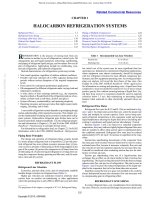
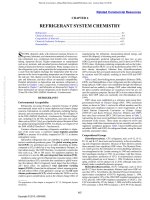
HIS chapter covers design and construction of household
refrigerators and freezers, the most common of which are illustrated in Figure 1.
Licensed for single user. © 2010 ASHRAE, Inc.
PRIMARY FUNCTIONS
Providing optimized conditions for preserving stored food is the
primary function of a refrigerator or freezer. Typically, this is done
by storing food at reduced temperature. Ice making is an essential
secondary function in some markets. A related product, the wine
cooler, provides optimum temperatures for storing wine, at temperatures from 7 to 13°C. Wine coolers are often manufactured by the
same companies using the same technologies as refrigerators and
freezers. Dual-use products combining a wine cooler and a refrigerator and/or freezer have also been manufactured.
Food Preservation
To preserve fresh food, a general storage temperature between 0
and 4°C is desirable. Higher or lower temperatures or a humid
atmosphere are more suitable for storing certain foods; the section
on Cabinets discusses special-purpose storage compartments
designed to provide these conditions. Food freezers and combination refrigerator-freezers for long-term storage are designed to hold
temperatures near –18 to –15°C and always below –13°C during
steady-state operation. In single-door refrigerators, the frozen food
space is usually warmer than this and is not intended for long-term
The preparation of this chapter is assigned to TC 8.9, Residential Refrigerators and Food Freezers.
storage. Optimum conditions for food preservation are detailed in
Chapters 19 to 24 and 28 to 42.
Special-Purpose Compartments
Special-purpose compartments provide a more suitable environment for storing specific foods. For example, some refrigerators
have a meat storage compartment that can maintain storage temperatures just above freezing and may include independent temperature
adjustment. Some models have a special compartment for fish,
which is maintained at approximately –1°C. High-humidity compartments for storing leafy vegetables and fresh fruit are found in
practically all refrigerators. These drawers or bins, located in the
fresh-food compartment, are generally tight-fitting to protect vulnerable foods from the desiccating effects of dry air circulating in
the general storage compartment. The dew point of this air
approaches the temperature of the evaporator surface. Because for
many refrigerators the general food storage compartment is cooled
with air from the freezer, the air dew point is below –18°C. The
desired conditions are maintained in the special storage compartments and drawers by (1) enclosing them to prevent air exchange
with the general storage area and (2) surrounding them with cold air
to maintain the desired temperature.
Maintaining desired fresh-food temperatures while avoiding
exchange with excessively dry air can also be achieved in a freshfood storage compartment cooled with a dedicated evaporator.
Higher humidity levels can be maintained in such a compartment
because of the higher evaporating temperature, and also by allowing
moisture collected on the evaporator to be transferred back into the
air by running the evaporator fan during the compressor off-cycle.
Fig. 1 Common Configurations of Contemporary Household Refrigerators and Freezers
Fig. 1 Common Configurations of Contemporary Household Refrigerators and Freezers
17.1
Copyright © 2010, ASHRAE
This file is licensed to Abdual Hadi Nema (). License Date: 6/1/2010
Licensed for single user. © 2010 ASHRAE, Inc.
17.2
2010 ASHRAE Handbook—Refrigeration (SI)
Such fresh-food compartments have been configured as allrefrigerators, or have been integrated with freezers in refrigeratorfreezers with two evaporators, using one compressor or separate
compressors.
Some refrigerators have special-purpose compartments for rapid
chilling, freezing, or thawing of food. Unlike rapid thawing in ambient air or in a microwave oven, rapid thawing using refrigerated air
maintains acceptable food preservation temperatures at the food’s
surface layer. All of these functions require high levels of heat transfer at the surface of the food, which is provided by enhanced airflow
delivered by a special-purpose fan.
New developments in food preservation technology address factors other than temperature and humidity that also affect food storage life. These factors include modified atmosphere (reduced
oxygen level, increased carbon dioxide level), removal of chemicals
such as ethylene that accelerate food spoilage, and using ozone both
to neutralize ethylene and other chemicals and to control bacteria
and other microbes. Although these technologies are not yet available or are uncommon in residential refrigerators, they represent
areas for future development and improvement in the primary function of food preservation. Separate products using ozone generation
and ethylene absorption have been developed and can be placed
inside the refrigerator to enhance food preservation.
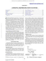
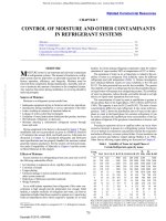
Fig. 2 Cabinet Cross Section Showing Typical
Contributions to Total Basic Heat Load
Ice and Water Service
Fig. 2 Cabinet Cross Section Showing Typical
Contributions to Total Basic Heat Load
Through a variety of manual or automatic means, most units
other than all-refrigerators provide ice. For manual operation, ice
trays are usually placed in the freezing compartment in a stream of
air that is substantially below 0°C or placed in contact with a
directly refrigerated evaporator surface.
Automatic Ice Makers. Automatic ice-making equipment in
household refrigerators is common in the United States. Almost all
U.S. automatic defrost refrigerators either include factory-installed
automatic ice makers or can accept field-installable ice makers.
The ice maker mechanism is located in the freezer section of the
refrigerator and requires attachment to a water line. Freezing rate is
primarily a function of system design. Water is frozen by refrigerated air passing over the ice mold. Because the ice maker must share
the available refrigeration capacity with the freezer and fresh-food
compartments, ice production is usually limited by design to 2 to
3 kg per 24 h. A rate of about 2 kg per 24 h, coupled with an ice storage container capacity of 3 to 5 kg, is adequate for most users.
Basic functions of an ice maker include the following:
1. Initiating ejection of ice as soon as the water is frozen. The need
for ejection is commonly determined by sensing mold temperature or by elapsed time.
2. Ejecting ice from the mold. Several designs free ice from the
mold with an electric heater and push it from the tray into an ice
storage container. In other designs, water frozen in a plastic tray
is ejected through twisting and rotation of the tray.
3. Driving the ice maker is done in most designs by a gear motor,
which operates the ice ejection mechanism and may also be used
to time the freezing cycle and the water-filling cycle and to operate the stopping means.
4. Filling the ice mold with a constant volume of water, regardless of
the variation in line water pressure, is necessary to ensure uniformsized ice cubes and prevent overfilling. This is done by timing a
solenoid flow control valve or by using a solenoid-operated,
fixed-volume slug valve.
5. Stopping ice production is necessary when the ice storage container is full. This is accomplished by using a feeler-type ice
level control or a weight control.
Many refrigerators include ice and water dispensers, generally
mounted in one of the doors. Ice is fed to the dispenser discharge
with an auger that pushes ice in the storage bucket to the dispenser
chute. Many of these units also can crush the ice prior to dispensing
it. A self-closing flap is used to seal the opening when the dispenser
is not in use. Water is chilled in the fresh-food compartment in a reservoir. Solenoid valves control flow of water to the dispenser.
CABINETS
Good cabinet design achieves the optimum balance of
•
•
•
•
Maximum food storage volume for floor area occupied by cabinet
Maximum utility, performance, convenience, and reliability
Minimum heat gain
Minimum cost to consumer
Use of Space
The fundamental factors in cabinet design are usable food storage capacity and external dimensions. Food storage volume has
increased considerably without a corresponding increase in external
cabinet dimensions, by using thinner but more effective insulation
and reducing the space occupied by the compressor and condensing
unit.
Methods of computing storage volume and shelf area are described in various countries’ standards [e.g., Association of Home
Appliance Manufacturers (AHAM) Standard HRF-1 for the United
States].
Thermal Loads
The total heat load imposed on the refrigerating system comes
from both external and internal heat sources. Relative values of the
basic or predictable components of the heat load (those independent
of use) are shown in Figure 2. External heaters are used to control
moisture condensation on cool external surfaces. The door gasket
region’s thermal loss includes conduction of heat through the gasket
and through the cabinet and door portions of this region, as well as
some infiltration. A large portion of the peak heat load may result
from door openings, food loading, and ice making, which are variable and unpredictable quantities dependent on customer use. As
the beginning point for the thermal design of the cabinet, the significant portions of the heat load are normally calculated and then confirmed by test. The largest predictable heat load is heat passing
through the cabinet walls.
This file is licensed to Abdual Hadi Nema (). License Date: 6/1/2010
Household Refrigerators and Freezers
Insulation
17.3
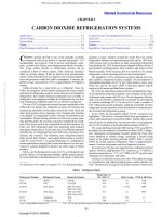
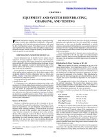
Fig. 3 Example Cross Section of Vacuum Insulation Panel
Licensed for single user. © 2010 ASHRAE, Inc.
Polyurethane foam insulation has been used in refrigeratorfreezer applications for over 40 years, originally using CFC-11 [an
ozone-depleting substance (ODS)] as the blowing agent. Because of
this ozone damage, the Montreal Protocol began curtailing its use in
1994. Most U.S. manufacturers of refrigerators and freezers then
converted to HCFC-141b as an interim blowing agent; those in
many other parts of the world moved straight to cyclopentane. Use
of HCFC-141b was phased out in 2003 in the United States, and in
most of the world. The three widely used blowing agents currently
in use are
• Cyclopentane, which has the lowest foam material cost, requires
high capital cost for safety in foam process equipment, increases
refrigerator energy use by about 4% compared to HCFC-141b,
and can be difficult and expensive to implement in locations with
very tight volatile organic compound restrictions.
• HFC-134a, which has the next lowest foam material cost,
requires high-pressure-rated metering and mixing equipment, and
increases refrigerator energy use by 8 to 10% compared to HCFC141b.
• HFC-245fa, which has the highest foam material cost, increases
refrigerator energy use by 0 to 2% compared to HCFC-141b,
requires some revision to existing foam equipment, and retains
insulating characteristics best over time.
Recently, flat vacuum-insulated panels (VIPs) have been
developed (Figure 3) to provide highly effective insulation values
down to 0.004 W/(m·K). A vacuum-insulated panel consists of a
low-thermal-conductance fill and an impermeable skin. Fine mineral powders such as silicas, fiberglass, open-cell foam, and silica
aerogel have all been used as fillers. The fill has sufficient compressive strength to support atmospheric pressure and can act as a radiation barrier. The skin must be highly impermeable, to maintain the
necessary vacuum level over a long period of time. Getter materials
are sometimes included to absorb small amounts of cumulative
vapor leakage. The barrier skin provides a heat conduction path
from the warm to the cool side of the panel, commonly referred to
as the edge effect, which must be minimized if a high overall insulation value is to be maintained. Metalized plastic films are sufficiently impermeable while causing minimal edge effect. They have
a finite permeability, so air gradually diffuses into the panel, degrading performance over time and limiting the useful life. There is also
a risk of puncture and immediate loss of vacuum. Depending on
how the vacuum panel is applied, the drastic reduction in insulation
value from loss of vacuum may result in condensation on the outside
wall of the cabinet, in addition to reduced energy efficiency. In commercial practice, vacuum-panel insulation is one of the least costeffective options for improving efficiency, but, where thicker walls
cannot be tolerated, they are a useful option for reaching specified
minimum efficiency levels.
External condensation of water vapor can be avoided by keeping exterior surfaces warmer than the ambient dew point. Condensation is most likely to occur around the hardware, on door
mullions, along the edge of door openings, and on any cold refrigerant tubing that may be exposed outside the cabinet. In a 32°C
room, no external surface temperature on the cabinet should be
more than 3 K below the room temperature. If it is necessary to raise
the exterior surface temperature to avoid sweating, this can be done
either by routing a loop of condenser tubing under the front flange of
the cabinet outer shell or by locating low-wattage wires or ribbon
heaters behind the critical surfaces. Most refrigerators that incorporate electric heaters have power-saving electrical switches that
allow the user to deenergize the heaters when they are not needed.
Some refrigerators with electric heaters use controls that adjust
average heater wattage based on ambient conditions to provide no
more heat input than necessary.
Fig. 3 Example Cross Section of Vacuum-Insulated Panel
Temporary condensation on internal surfaces may occur with
frequent door openings, so the interior of the general storage compartment must be designed to avoid objectionable accumulation or
drippage.
Figure 2 shows the design features of the throat section where the
door meets the face of the cabinet. On products with metal liners,
thermal breaker strips prevent metal-to-metal contact between inner
and outer panels. Because the air gap between the breaker strip and
the door panel provides a low-resistance heat path to the door gasket, the clearance should be kept as small as possible and the breaker
strip as wide as practicable. When the inner liner is made of plastic
rather than steel, there is no need for separate plastic breaker strips
because they are an integral part of the liner.
Cabinet heat leakage can be reduced by using door gaskets with
more air cavities to reduce conduction or by using internal secondary gaskets. Care must be taken not to exceed the maximum door
opening force as specified in safety standards; in the United States,
this is specified in 16CFR1750.
Structural supports, if necessary to support and position the food
compartment liner from the outer shell of the cabinet, are usually
constructed of a combination of steel and plastics to provide adequate strength with maximum thermal insulation.
Internal heat loads that must be overcome by the system’s refrigerating capacity are generated by periodic automatic defrosting, ice
makers, lights, timers, fan motors used for air circulation, and heaters used to prevent undesirable internal cabinet sweating or frost
build-up or to maintain the required temperature in a compartment.
Structure and Materials
The external shell of the cabinet is usually a single fabricated
steel structure that supports the inner food compartment liner, door,
and refrigeration system. Space between the inner and outer cabinet
walls is usually filled with foam-in-place insulation. In general, the
door and breaker strip construction is similar to that shown in Figure
2, although breaker strips and food liners formed of a single plastic
sheet are also common. The doors cover the whole front of the cabinet, and plastic sheets become the inner surface for the doors, so no
separate door breaker strips are required. Door liners are usually
formed to provide an array of small door shelves and racks. Cracks
and crevices are avoided, and edges are rounded and smooth to facilitate cleaning. Interior lighting, when provided, is usually incandescent lamps controlled by mechanically operated switches actuated
by opening the refrigerator door(s) or chest freezer lid.
Cabinet design must provide for the special requirements of the
refrigerating system. For example, it may be desirable to refrigerate
the freezer section by attaching evaporator tubing directly to the
food compartment liner. Also, it may be desirable, particularly with
food freezers, to attach condenser tubing directly to the shell of the
This file is licensed to Abdual Hadi Nema (). License Date: 6/1/2010
Licensed for single user. © 2010 ASHRAE, Inc.
17.4
cabinet to prevent external sweating. Both designs influence cabinet
heat leakage and the amount of insulation required.
The method of installing the refrigerating system into the cabinet
is also important. Frequently, the system is installed in two or more
component pieces and then assembled and processed in the cabinet.
Unitary installation of a completed system directly into the cabinet
allows the system to be tested and charged beforehand. Cabinet design must be compatible with the method of installation chosen. In
addition, forced-air systems frequently require ductwork in the cabinet or insulation spaces.
The overall structure of the cabinet must be strong enough to
withstand shipping (and thus strong enough to withstand daily
usage). However, additional support is typically provided in packaging material. Plastic food liners must withstand the thermal
stresses they are exposed to during shipping and usage, and they
must be unaffected by common contaminants encountered in kitchens. Shelves must be designed not to deflect excessively under the
heaviest anticipated load. Standards typically require that refrigerator doors and associated hardware withstand a minimum of 300 000
door openings.
Foam-in-place insulation has had an important influence on
cabinet design and assembly procedures. Not only does the foam’s
superior thermal conductivity allow wall thickness to be reduced,
but its rigidity and bonding action usually eliminate the need for
structural supports. The foam is normally expanded directly into
the insulation space, adhering to the food compartment liner and
the outer shell. Unfortunately, this precludes simple disassembly of
the cabinet for service or repairs.
Outer shells of refrigerator and freezer cabinets are now typically
of prepainted steel, thus reducing the volatile emissions that accompany the finishing process and providing a consistently durable finish to enhance product appearance and avoid corrosion.
Use of Plastics. As much as 7 to 9 kg of plastic is incorporated
in a typical refrigerator or freezer. Use of plastic is increasing for
reasons including a wide range of physical properties; good bearing
qualities; electrical insulation; moisture and chemical resistance;
low thermal conductivity; ease of cleaning; appearance; possible
multifunctional design in single parts; transparency, opacity, and
colorability; ease of forming and molding; and potential for lower
cost.
A few examples illustrate the versatility of plastics. High-impact
polystyrene (HIPs) and acrylonitrile butadiene styrene (ABS) plastics are used for inner door liners and food compartment liners. In
these applications, no applied finish is necessary. These and similar
thermoplastics such as polypropylene and polyethylene are also
selected for evaporator doors, baffles, breaker strips, drawers, pans,
and many small items. The good bearing qualities of nylon and acetal are used to advantage in applications such as hinges, latches, and
rollers for sliding shelves. Gaskets, both for the refrigerator and for
the evaporator doors, are generally made of vinyl.
Many items (e.g., ice cubes, butter) readily absorb odors and
tastes from materials to which they are exposed. Accordingly, manufacturers take particular care to avoid using any plastics or other
materials that impart an odor or taste in the interior of the cabinet.
Moisture Sealing
For the cabinet to retain its original insulating qualities, the insulation must be kept dry. Moisture may get into the insulation
through leakage of water from the food compartment liner, through
the defrost water disposal system, or, most commonly, through
vapor leaks in the outer shell.
The outer shell is generally crimped, seam welded, or spot
welded and carefully sealed against vapor transmission with mastics
and/or hot-melt asphaltic or wax compounds at all joints and seams.
In addition, door gaskets, breaker strips, and other parts should provide maximum barriers to vapor flow from the room air to the insulation. When refrigerant evaporator tubing is attached directly to the
2010 ASHRAE Handbook—Refrigeration (SI)
food compartment liner, as is generally done in chest freezers, moisture does not migrate from the insulation space, and special efforts
must be made to vapor-seal this space.
Although urethane foam insulation tends to inhibit moisture
migration, it tends to trap water when migrating vapor reaches a
temperature below its dew point. The foam then becomes permanently wet, and its insulation value is decreased. For this reason, a
vaportight exterior cabinet is equally important with foam insulation.
Door Latching and Entrapment
Door latching is accomplished by mechanical or magnetic
latches that compress relatively soft compression gaskets made of
vinyl compounds. Gaskets with embedded magnetic materials are
generally used. Chest freezers are sometimes designed so that the
mass of the lid acts to compress the gasket, although most of the
mass is counterbalanced by springs in the hinge mechanism.
Safety standards mandate that appliances with any space large
enough for a child to get into must be able to be opened from the
inside. Doors or lids often must be removed when an appliance is
discarded, as well.
Standards also typically mandate that any key-operated lock
require two independent movements to actuate the lock, or be of a
type that automatically ejects the key when unlocked. Some standards (e.g., IEC Standard 60335-2-24; UL Standard 250) also mandate safety warning markings.
Cabinet Testing
Specific tests necessary to establish the adequacy of the cabinet
as a separate entity include (1) structural tests, such as repeated
twisting of the cabinet and door; (2) door slamming test; (3) tests for
vapor-sealing of the cabinet insulation space; (4) odor and taste
transfer tests; (5) physical and chemical tests of plastic materials;
and (6) heat leakage tests. Cabinet testing is also discussed in the
section on Performance and Evaluation.
REFRIGERATING SYSTEMS
Most refrigerators and freezers use vapor-compression refrigeration systems. However, some smaller refrigerators use absorption
systems (Bansal and Martin 2000), and, in some cases, thermoelectric (Peltier-effect) refrigeration. Applications for water/ammonia
absorption systems have developed for recreational vehicles, picnic
coolers, and hotel room refrigerators, where noise is an issue. This
chapter covers only the vapor-compression cycle in detail, because
it is much more common than these other systems. Other electrically powered systems compare unfavorably to vapor-compression
systems in terms of manufacturing and operating costs. Typical
coefficients of performance of the three most practical refrigeration
systems are as follows for a –18°C freezer and 32°C ambient:
Thermoelectric
Absorption
Vapor compression
Approximately 0.1 W/W
Approximately 0.2 W/W
Approximately 1.7 W/W
An absorption system may operate from natural gas or propane
rather than electricity at a lower cost per unit of energy, but the initial cost, size, and mass have made it unattractive to use gas systems
for major appliances where electric power is available. Because of
its simplicity, thermoelectric refrigeration could replace other systems if (1) an economical and efficient thermoelectric material were
developed and (2) design issues such as the need for a direct current
(dc) power supply and an effective means for transferring heat from
the module were addressed.
Vapor-compression refrigerating systems used with modern
refrigerators vary considerably in capacity and complexity, depending on the refrigerating application. They are hermetically sealed
and normally require no replenishment of refrigerant or oil during
This file is licensed to Abdual Hadi Nema (). License Date: 6/1/2010
Household Refrigerators and Freezers
the appliance’s useful life. System components must provide optimum overall performance and reliability at minimum cost. In addition, all safety requirements of the appropriate safety standard (e.g.,
IEC Standard 60335-2-24; UL Standard 250) must be met. The
fully halogenated refrigerant R-12 was used in household refrigerators for many years. However, because of its strong ozone depletion property, appliance manufacturers have replaced R-12 with
environmentally acceptable R-134a or isobutane.
Design of refrigerating systems for refrigerators and freezers has
improved because of new refrigerants and oils, wider use of aluminum, and smaller and more efficient motors, fans, and compressors.
These refinements have kept the vapor-compression system in the
best competitive position for household application.
Refrigerating Circuit
Licensed for single user. © 2010 ASHRAE, Inc.
Figure 4 shows a common refrigerant circuit for a vaporcompression refrigerating system. In the refrigeration cycle,
1. Electrical energy supplied to the motor drives a positivedisplacement compressor, which draws cold, low-pressure refrigerant vapor from the evaporator and compresses it.
2. The resulting high-pressure, high-temperature discharge gas
then passes through the condenser, where it is condensed to a liquid while heat is rejected to the ambient air.
3. Liquid refrigerant passes through a metering (pressure-reducing)
capillary tube to the evaporator, which is at low pressure.
4. The low-pressure, low-temperature liquid in the evaporator
absorbs heat from its surroundings, evaporating to a gas, which
is again withdrawn by the compressor.
Note that energy enters the system through the evaporator (heat
load) and through the compressor (electrical input). Thermal energy
is rejected to the ambient by the condenser and compressor shell. A
portion of the capillary tube is usually soldered to the suction line to
form a heat exchanger. Cooling refrigerant in the capillary tube with
the suction gas increases capacity and efficiency.
A strainer-drier is usually placed ahead of the capillary tube to
remove foreign material and moisture. Refrigerant charges of 150 g
or less are common. A thermostat (or cold control) cycles the compressor to provide the desired temperatures in the refrigerator. During the off cycle, the capillary tube allows pressures to equalize
throughout the system.
Materials used in refrigeration circuits are selected for their
(1) mechanical properties, (2) compatibility with the refrigerant and
oil on the inside, and (3) resistance to oxidation and galvanic corrosion on the outside. Evaporators are usually made of bonded aluminum sheets or aluminum tubing, either with integral extruded fins or
with extended surfaces mechanically attached to the tubing. Evaporators in cold-wall appliances are typically steel, copper, or aluminum. Condensers are usually made of steel tubing with an extended
surface of steel sheet or wire. Steel tubing is used on the high-pressure
side of the system, which is normally dry, and copper is used for
Fig. 4
Refrigeration Circuit
Fig. 4 Refrigeration Circuit
17.5
suction tubing, where condensation can occur. Because of its ductility, corrosion resistance, and ease of brazing, copper is used for
capillary tubes and often for small connecting tubing. Wherever aluminum tubing comes in contact with copper or iron, it must be protected against moisture to avoid electrolytic corrosion.
Defrosting
Defrosting is required because moisture enters the cabinet from
some food items (e.g., fresh fruit and vegetables) and from ambient
air (through door openings or infiltration). Over time, this moisture
collects on the evaporator surface as frost, which can reduce evaporator performance and must be removed by a defrosting process.
Manual Defrost. Manufacturers still make a few models that use
manual defrost, in which the cooling effect is generated by natural
convection of air over a refrigerated surface (evaporator) located at
the top of the food compartment. The refrigerated surface forms
some of the walls of a frozen food space, which usually extends
across the width of the food compartment. Defrosting is typically
accomplished by manually turning off the temperature control
switch.
Cycle Defrosting (Partial Automatic Defrost). Combination
refrigerator-freezers sometimes use two separate evaporators for the
fresh food and freezer compartments. The fresh food compartment
evaporator defrosts during each off cycle of the compressor, with
energy for defrosting provided mainly by heat leakage (typically 10
to 20 W) into the fresh food compartment, though usually assisted
by an electric heater, which is turned on when the compressor is
turned off. The cold control senses the temperature of the fresh food
compartment evaporator and cycles the compressor on when the
evaporator surface is about 3°C. The freezer evaporator requires
infrequent manual defrosting. This system is also commonly used in
all-refrigerator units (see Figure 1 note).
Frost-Free Systems (Automatic Defrost). Most combination
refrigerator-freezers and upright food freezers are refrigerated by air
that is fan-blown over a single evaporator concealed from view.
Because the evaporator is colder than the freezer compartment, it
collects practically all of the frost, and there is little or no permanent
frost accumulation on frozen food or on exposed portions of the
freezer compartment. The evaporator is defrosted automatically by
an electric heater located under the heat exchanger or by hot refrigerant gas, and the defrosting period is short, to limit food temperature rise. The resulting water is disposed of automatically by
draining to the exterior, where it is evaporated in a pan located in the
warm condenser compartment. A timer usually initiates defrosting
at intervals of up to 24 h. If the timer operates only when the compressor runs, the accumulated time tends to reflect the probable frost
load.
Adaptive Defrost. Developments in electronics have allowed
the introduction of microprocessor-based control systems to some
household refrigerators. An adaptive defrost function is usually
included in the software. Various parameters are monitored so that
the period between defrosts varies according to actual conditions of
use. Adaptive defrost tends to reduce energy consumption and
improve food preservation.
Forced Heat for Defrosting. All no-frost systems add heat to the
evaporator to accelerate melting during the short defrosting cycle.
The most common method uses a 300 to 1000 W electric heater. The
traditional defrost cycle is initiated by a timer, which stops the compressor and energizes the heater.
When the evaporator has melted all the frost, a defrost termination thermostat opens the heater circuit. In most cases, the compressor is not restarted until the evaporator has drained for a few minutes
and the system pressures have stabilized; this reduces the applied
load for restarting the compressor. Commonly used defrost heaters
include metal-sheathed heating elements in thermal contact with
evaporator fins and radiant heating elements positioned to heat the
evaporator.
This file is licensed to Abdual Hadi Nema (). License Date: 6/1/2010
Licensed for single user. © 2010 ASHRAE, Inc.
17.6
2010 ASHRAE Handbook—Refrigeration (SI)
Evaporator
Condenser
The manual defrost evaporator is usually a box with three or
four sides refrigerated. Refrigerant may be carried in tubing brazed
to the walls of the box, or the walls may be constructed from double
sheets of metal that are brazed or metallurgically bonded together
with integral passages for the refrigerant. In this construction, often
called a roll bond evaporator, the walls are usually aluminum, and
special attention is required to avoid (1) contamination of the surface with other metals that would promote galvanic corrosion and
(2) configurations that may be easily punctured during use.
The cycle defrost evaporator for the fresh food compartment is
designed for natural defrost operation and is characterized by its low
thermal capacity. It may be either a vertical plate, usually made from
bonded sheet metal with integral refrigerant passages, or a serpentine coil with or without fins. In either case, the evaporator should be
located near the top of the compartment and be arranged for good
water drainage during the defrost cycle. Defrost occurs during the
compressor off-cycle as the evaporator warms up above freezing
temperature. In some designs, the evaporator is located in an air duct
remote from the fresh food space, with air circulated continuously
by a small fan.
The frost-free evaporator is usually a forced-air fin-and-tube
arrangement designed to minimize frost accumulation, which tends
to be relatively rapid in a single-evaporator system. The coil is usually arranged for airflow parallel to the fins’ long dimension.
Fins may be more widely spaced at the air inlet to provide for
preferential frost collection and to minimize its air restriction
effects. All surfaces must be heated adequately during defrost to
ensure complete defrosting, and provision must be made for draining and evaporating the defrost water outside the food storage
spaces. Variations on the common flat-fin-and-tube evaporators
include spine fin designs and egg-crate evaporators. A spine fin
evaporator consists of a serpentine of tubing with an assembly of
spine fins attached to it externally (Beers 1991). The fin assembly is
a flat sheet of aluminum with spines formed in it, which is wrapped
helically around the tube. Egg-crate evaporators (Bansal et al. 2001)
are made of aluminum with continuous rectangular fins; fin layers
are press-fitted onto the serpentine evaporator tube. These evaporators work in counter/parallel/cross flow configurations. Figure 5
shows details of spine-fin and egg-crate evaporators.
Freezers. Evaporators for chest freezers usually consist of tubing that is in good thermal contact with the exterior of the food compartment liner. Tubing is generally concentrated near the top of the
liner, with wider spacing near the bottom to take advantage of
natural convection of air inside. Most non-frost-free upright food
freezers have refrigerated shelves and/or surfaces, sometimes concentrated at the top of the food compartment. These may be connected in series with an accumulator at the exit end. Frost-free
freezers and refrigerator-freezers usually use a fin-and-tube evaporator and an air-circulating fan.
The condenser is the main heat-rejecting component in the
refrigerating system. It may be cooled by natural draft on freestanding refrigerators and freezers or fan-cooled on larger models
and on models designed for built-in applications.
The natural-draft condenser is located on the back wall of the
cabinet and is cooled by natural air convection under the cabinet and
up the back. The most common form consists of a flat serpentine of
steel tubing with steel cross wires welded on 6 mm centers on one
or both sides perpendicular to the tubing. Tube-on-sheet construction may also be used.
The hot-wall condenser, another common natural-draft arrangement, consists of condenser tubing attached to the inside surface of
the cabinet shell. The shell thus acts as an extended surface for heat
dissipation. With this construction, external sweating is seldom a
problem. Bansal and Chin (2003) provide an in-depth analysis of
both these types of condensers.
The forced-draft condenser may be of fin-and-tube, folded
banks of tube-and-wire, or tube-and-sheet construction. Various
forms of condenser construction are used to minimize clogging
caused by household dust and lint. The compact, fan-cooled condensers are usually designed for low airflow rates because of noise
limitations. Air ducting is often arranged to use the front of the
machine compartment for entrance and exit of air. This makes the
cooling air system largely independent of the location of the refrigerator and allows built-in applications.
In hot and humid climates, defrosted water may not evaporate
easily (Bansal and Xie 1999). Part of the condenser may be located
under the defrost water evaporating pan to promote water evaporation.
For compressor cooling, the condenser may also incorporate a
section where partially condensed refrigerant is routed to an oilcooling loop in the compressor. Here, liquid refrigerant, still at high
pressure, absorbs heat and is reevaporated. The vapor is then routed
through the balance of the condenser, to be condensed in the normal
manner.
Condenser performance may be evaluated directly on calorimeter test equipment similar to that used for compressors. However,
final condenser design must be determined by performance tests on
the refrigerator under a variety of operating conditions.
Generally, the most important design requirements for a condenser include (1) sufficient heat dissipation at peak-load conditions; (2) refrigerant holding capacity that prevents excessive
pressures during pulldown or in the event of a restricted or plugged
capillary tube; (3) good refrigerant drainage to minimize refrigerant
trapping in the bottom of loops in low ambients, off-cycle losses,
and the time required to equalize system pressures; (4) an external
surface that is easily cleaned or designed to avoid dust and lint accumulation; (5) a configuration that provides adequate evaporation of
defrost water; and (6) an adequate safety factor against bursting.
Fans
Fig. 5 Spine-Fin and Egg-Crate Evaporator Detail
Fig. 5
Spine-Fin and Egg-Crate Evaporator Detail
Advancements in small motor technology and electronic controls make high-efficiency fans advantageous. High-efficiency fan
motors are typically electronically-commutated dc motors. They
can be variable speed over a broad speed range. Many dc fan motors for modern refrigerators are designed for 120 V ac power input, including both the motor and power conversion in as single
package. Energy improvements are approximately two or more
times that of conventional ac shaded-pole fan motors. Another fan
motor option with an intermediate efficiency level is the permanent
split capacitor (PSC) motor; however, this motor type is more often
used in larger systems (i.e., commercial refrigerators).
Fan impellers in modern refrigerators are generally molded
plastic with efficient shapes. Achieving peak fan performance also
requires good mating of the fan and orifice, and selection of a fan/
motor suitable for the airflow and pressure rise requirements.
This file is licensed to Abdual Hadi Nema (). License Date: 6/1/2010
Household Refrigerators and Freezers
Licensed for single user. © 2010 ASHRAE, Inc.
Capillary Tube
The most commonly used refrigerant metering device is the capillary tube, a small-bore tube connecting the outlet of the condenser
to the inlet of the evaporator. The regulating effect of this simple
control device is based on the principle that a given mass of liquid
passes through a capillary more readily than the same mass of gas at
the same pressure. Thus, if uncondensed refrigerant vapor enters the
capillary, mass flow is reduced, giving the refrigerant more cooling
time in the condenser. On the other hand, if liquid refrigerant tends
to back up in the condenser, the condensing temperature and pressure rise, resulting in an increased mass flow of refrigerant. Under
normal operating conditions, a capillary tube gives good performance and efficiency. Under extreme conditions, the capillary either
passes considerable uncondensed gas or backs liquid refrigerant
well up into the condenser. Figure 6 shows the typical effect of capillary refrigerant flow rate on system performance. Because of these
shortcomings and the difficulty of maintaining a match between the
capillary restriction and the output of variable-pump-rate compressors, electronically controlled expansion valves are now used.
A capillary tube has the advantage of extreme simplicity and no
moving parts. It also lends itself well to being soldered to the suction
line for heat exchange purposes. This positioning prevents sweating
of the otherwise cold suction line and increases refrigerating capacity and efficiency. Another advantage is that pressure equalizes
throughout the system during the off cycle and reduces the starting
torque required of the compressor motor. The capillary is the narrowest passage in the refrigerant system and the place where low
temperature first occurs. For that reason, a combination strainerdrier is usually located directly ahead of the capillary to prevent it
from being plugged by ice or any foreign material circulating
through the system (see Figure 4). See Bansal and Xu (2002), Dirik
et al. (1994), Mezavila and Melo (1996), and Wolf and Pate (2002)
on design and modeling of capillary tubes.
Selection. Optimum metering action can be obtained by varying
the tube’s diameter or length. Factors such as the physical location
of system components and heat exchanger length (900 mm or more
is desirable) may help determine the optimum length and bore of the
capillary tube for any given application. Capillary tube selection is
covered in detail in Chapter 11.
Once a preliminary selection is made, an experimental unit can
be equipped with three or more different capillaries that can be activated independently. System performance can then be evaluated by
using in turn capillaries with slightly different flow characteristics.
17.7
Final capillary selection requires optimizing performance under
both no-load and pulldown conditions, with maximum and minimum ambient and load conditions. The optimum refrigerant charge
can also be determined during this process.
Compressor
Although a more detailed description of compressors can be
found in Chapter 37 of the 2008 ASHRAE Handbook—HVAC Systems and Equipment, a brief discussion of the small compressors
used in household refrigerators and freezers is included here.
These products use positive-displacement compressors in which
the entire motor-compressor is hermetically sealed in a welded steel
shell. Capacities range from about 70 to 600 W measured at the
ASHRAE rating conditions of –23.3°C evaporator, 54.4°C condenser, and 32.2°C ambient, with suction gas superheated to 32.2°C
and liquid subcooled to 32.2°C, or Comité Européen des Constructeurs de Matériel Frigorifique (CECOMAF) rating conditions
of –23.3°C evaporator, 55°C condenser, and 32.2°C ambient, with
suction gas superheated to 32.2°C and liquid subcooled to 55°C.
Design emphasizes ease of manufacturing, reliability, low cost,
quiet operation, and efficiency. Figure 7 illustrates the two reciprocating piston compressor mechanisms that are used in most conventional refrigerators and freezers; no one type is much less costly than
the others. Rotary compressors have also been used in refrigerators.
They are somewhat more compact than reciprocating compressors,
but a greater number of close tolerances is involved in their manufacture. The majority of modern refrigerator compressors are of
reciprocating connecting rod design.
Generally, these compressors are directly driven by two-pole
(3450 rpm on 60 Hz, 2850 on 50 Hz) squirrel cage induction motors.
Field windings are insulated with special wire enamels and plastic
slot and wedge insulation; all are chosen for their compatibility with
the refrigerant and oil. During continuous runs at rated voltage,
Fig. 7 Refrigerator Compressors
Fig. 6 Typical Effect of Capillary Tube Selection on Unit Running Time
Fig. 6 Typical Effect of Capillary Tube Selection on
Unit Running Time
Fig. 7 Refrigerator Compressors
This file is licensed to Abdual Hadi Nema (). License Date: 6/1/2010
17.8
motor winding temperatures may be as high as 120°C when tested
in a 43°C ambient temperature. In addition to maximum operating
efficiency at normal running conditions, the motor must provide
sufficient torque at the anticipated extremes of line voltage for starting and temporary peak loads from start-up and pulldown of a warm
refrigerator and for loads associated with defrosting.
Starting torque is provided by a split-phase winding circuit,
which in the larger motors may include a starting capacitor. When
the motor comes up to speed, an external electromagnetic relay, positive temperature coefficient (PTC) device, or electronic switching
device disconnects the start winding. A run capacitor is often used
for greater motor efficiency. Motor overload protection is provided
by an automatically resetting switch, which is sensitive to a combination of motor current and compressor case temperature or to internal winding temperature.
The compressor is cooled by rejecting heat to the surroundings.
This is easily accomplished with a fan-cooled system. However, an
oil-cooling loop carrying partially condensed refrigerant may be
necessary when the compressor is used with a natural-draft condenser and in some forced-draft systems above 300 W.
Licensed for single user. © 2010 ASHRAE, Inc.
Variable-Speed Compressors
Several manufacturers of residential refrigerator compressors offer variable-speed reciprocating compressors, which provide refrigeration capacity modulation. These compressors consist of a welded
hermetic motor-compressor and an electronic drive that converts
line power into a variable-frequency output to drive the compressor
at the desired speed. Most variable-speed compressors in the residential refrigerator capacity range (typically under 0.2 kW of nominal shaft power) are driven by a permanent-magnet rotor, brushless
dc motor because of its higher efficiency in this power range. The
controller also provides for commutation, synchronizing the electric
input (typically a three-phase square wave) with the angular position of the permanent-magnet rotor’s magnetic poles. The typical
speed range is 1600 to 4500 rpm (close to a 3:1 ratio of maximum
to minimum speed). The minimum speed is that required to maintain compressor lubrication; at the maximum speed, performance
begins to deteriorate because of pressure losses in the compressor
reed valves and other speed-related losses.
With refrigeration capacity modulation provided by a variablespeed compressor, cabinet temperature control can be provided by
varying speed and capacity to match the load instead of cycling the
compressor on and off over a temperature control dead band around
a set point. In principle, with an appropriate temperature control algorithm [e.g., proportional-integral-derivative (PID) control], nearly
constant cabinet temperature can be maintained. Many variablespeed compressors and their controllers actually provide two or more
discrete speeds, rather than continuously variable speed, to avoid
operation at a natural vibration frequency that might exist within the
operating speed range, and to attempt to simplify application of the
compressor to the refrigerator. In this case, a suitable cabinet temperature control is needed.
A variable-speed compressor in a typical frost-free refrigeratorfreezer can significantly reduce energy consumption [as measured
by the U.S. Department of Energy’s closed-door energy test
(10CFR430)]. The efficiency gain is mainly caused by the permanent-magnet rotor motor’s higher efficiency, elimination or significant reduction of on/off cycling losses, and better use of evaporator
and condenser capacity by operating continuously at low capacity
instead of cycling on/off at high capacity, which results in a higher
evaporating temperature and a lower condensing temperature. However, achieving optimum efficiency with variable-speed compressors generally requires simultaneous use of variable-speed fans.
Run time at the compressor’s low speed is longer than for a singlespeed system, so fan energy use increases, unless fan input power is
reduced by using brushless dc fans, which can reduce speed.
2010 ASHRAE Handbook—Refrigeration (SI)
Linear Compressors
Linear compressors derive from linear free-piston Stirling
engine-alternator technology. A linear compressor is a reciprocating
piston compressor whose piston is driven by a linear (not a rotating)
motor. The piston oscillates on a rather stiff mechanical spring. The
resulting mass/spring rate determined natural frequency is the frequency at which the compressor must operate. The motor is electronically driven to provide stroke control: for good efficiency, the
piston travel must closely approach the cylinder head to minimize
clearance volume. Capacity modulation can be provided by reducing the stroke. Unusually high efficiencies have been claimed for
linear compressors, but few have been produced.
Temperature Control System
Temperature is often controlled by a thermostat consisting of
an electromechanical switch actuated by a temperature-sensitive
power element that has a condensable gas charge, which operates a
bellows or diaphragm. At operating temperature, this charge is in a
two-phase state, and the temperature at the gas/liquid interface
determines the pressure on the bellows. To maintain temperature
control at the bulb end of the power element, the bulb must be the
coldest point at all times.
The thermostat must have an electrical switch rating for the
inductive load of the compressor and other electrical components
carried through the switch. The thermostat is usually equipped with
a shaft and knob for adjusting the operating temperature. Electronic
temperature controls, some using microprocessors, are becoming
more common. They allow better temperature performance by
reacting faster to temperature and load changes in the appliance, and
do not have the constraint of requiring the sensor to be colder than
the thermostat body or the phial tube connecting them. In some
cases, both compartment controls use thermistor-sensing devices
that relay electronic signals to the microprocessor. Electronic temperature sensors provide real-time information to the control system
that can be customized to optimize energy performance and temperature management. Electronic control systems provide a higher
degree of independence in temperature adjustments for the two
main compartments. Electronics also allow the use of variablespeed fans and motorized dampers to further optimize temperature
and energy performance.
In the simple gravity-cooled system, the controller’s sensor is
normally in close thermal contact with the evaporator. The location
of the sensor and degree of thermal contact are selected to produce
both a suitable cycling frequency for the compressor and the desired
refrigerator temperature. For push-button defrosting, small refrigerators sold in Europe are sometimes equipped with a manually operated push-button control to prevent the compressor from coming on
until defrost temperatures are reached; afterward, normal cycling is
resumed.
In a combination refrigerator-freezer with a split air system, location of the sensor(s) depends on whether an automatic damper control is used to regulate airflow to the fresh food compartment. When
an auxiliary control is used, the sensor is usually located where it can
sense the temperature of air leaving the evaporator. In manualdamper-controlled systems, the sensor is usually placed in the cold
airstream to the fresh food compartment. Sensor location is frequently related to the damper effect on the airstream. Depending on
the design of this relationship, the damper may become the freezer
temperature adjustment or it may serve the fresh food compartment,
with the thermostat being the adjustment for the other compartment.
The temperature sensor should be located to provide a large enough
temperature differential to drive the switch mechanism, while avoiding (1) excessive cycle length; (2) short cycling time, which can
cause compressor starting problems; and (3) annoyance to the user
from frequent noise level changes. Some combination refrigeratorfreezers manage the temperature with a sensor for each compartment. These may manage the compressor, an automatic damper,
This file is licensed to Abdual Hadi Nema (). License Date: 6/1/2010
Household Refrigerators and Freezers
variable-speed fans, or a combination of these. Such controls are
almost certainly microprocessor-based.
Licensed for single user. © 2010 ASHRAE, Inc.
System Design and Balance
A principal design consideration is selecting components that
will operate together to give the optimum system performance and
efficiency when total cost is considered. Normally, a range of combinations of values for these components meets the performance
requirements, and the lowest cost for the required efficiency is
only obtained through careful analysis or a series of tests (usually
both). For instance, for a given cabinet configuration, food storage
volume, and temperature, the following can be traded off against
one another: (1) insulation thickness and overall shell dimensions,
(2) insulation material, (3) system capacity, and (4) individual
component performance (e.g., fan, compressor, and evaporator).
Each of these variables affects total cost and efficiency, and most
can be varied only in discrete steps.
The experimental procedure involves a series of tests. Calorimeter tests may be made on the compressor and condenser, separately
or together, and on the compressor and condenser operating with the
capillary tube and heat exchanger. Final component selection
requires performance testing of the system installed in the cabinet.
These tests also determine refrigerant charge, airflows for the
forced-draft condenser and evaporator, temperature control means
and calibration, necessary motor protection, and so forth. The section on Performance and Evaluation covers the final evaluation tests
made on the complete refrigerator. Interaction between components
is further addressed in Chapter 5. This experimental procedure
assumes knowledge (equations or graphs) of the performance characteristics of the various components, including cabinet heat leakage and the heat load imposed by the customer. The analysis may be
performed manually point by point. If enough component information exists, it can be entered into a computer simulation program
capable of responding to various design conditions or statistical situations. Although the available information may not always be adequate for an accurate analysis, this procedure is often useful,
although confirming tests must follow.
Processing and Assembly Procedures
All parts and assemblies that are to contain refrigerant are processed to avoid unwanted substances or remove them from the final
sealed system and to charge the system with refrigerant and oil
(unless the latter is already in the compressor as supplied). Each
component should be thoroughly cleaned and then stored in a clean,
dry condition until assembly. The presence of free water in stored
parts produces harmful compounds such as rust and aluminum
hydroxide, which are not removed by the normal final assembly
process. Procedures for dehydration, charging, and testing may be
found in Chapter 8.
Assembly procedures are somewhat different, depending on
whether the sealed refrigerant system is completed as a unit before
being assembled to the cabinet, or components of the system are
first brought together on the cabinet assembly line. With the unitary
installation procedure, the system may be tested for its ability to
refrigerate and then be stored or delivered to the cabinet assembly
line.
PERFORMANCE AND EVALUATION
Once the unit is assembled, laboratory testing, supplemented by
field-testing, is necessary to determine actual performance. This
section describes various performance requirements and related
evaluation procedures.
Environmental Test Rooms
Climate-controlled test rooms are essential for performancetesting refrigerators and freezers. The test chambers must be able to
17.9
maintain environmental conditions specified in the various test
methods, which range from 10 to 43°C and humidity levels between
45 and 75% rh, depending on the type of test and method used. Most
standards require test chamber temperatures to be maintainable to
within 0.5 K of the desired value. The temperature gradient and air
circulation in the room should also be maintained closely. To provide more flexibility in testing, it may be desirable to have an additional test room that can cover the range down to –18°C for things
such as plastic liner stress-crack testing. At least one test room
should be able to maintain a desired relative humidity within a tolerance of ±2% up to 85% rh.
All instruments should be calibrated at regular intervals. Instrumentation should have accuracy and response capabilities of sufficient quality to measure the dynamics of the systems tested.
Computerized data acquisition systems that record power, current, voltage, temperature, humidity, and pressure are used in testing
refrigerators and freezers. Refrigerator test laboratories have developed automated means of control and data acquisition (with computerized data reduction output) and automated test programming.
Standard Performance Test Procedures
Association of Home Appliance Manufacturers (AHAM) Standard HRF-1 describes tests for determining the performance of
refrigerators and freezers in the United States. It specifies methods
for test setup, standard ambient conditions, power supply, and
means for measuring all relevant parameters and data reduction.
Other common test methods include International Electrotechnical
Commission (IEC) Standard 62552, which is the current procedure
for European and other nations, and the Japanese Standards Association’s International Standard (JIS) C 9801. Other test procedures
also are in use, but they are generally modified variations of these
three procedures. Methods discussed in this section are primarily
taken from the AHAM test procedure; other methods used are outlined in the section on Energy Consumption Tests. Test procedures
include the following.
Energy Consumption Tests. In many countries (see, e.g., the
Collaborative Labeling and Appliance Standards Program at www.
CLASPonline.org), regulators set efficiency standards for residential appliances. Periodically, these standards are reviewed and
revised to promote incorporation of emerging energy-saving technologies. For refrigerators and freezers, these standards are set in
terms of the maximum annual electric energy consumption, which
is measured according to a prescribed test procedure. In the United
States, this is done under the Department of Energy’s (DOE)
National Appliance Energy Conservation Act (NAECA), which references the test procedure in AHAM Standard HRF-1.
Different test procedures, often adapted to local conditions, are
used around the world to determine energy consumption of household refrigerators (Table 1). Most tests measure energy consumption
at a food compartment internal temperature of 3 to 5°C, freezer compartment temperatures of –18 to –15°C, and a steady ambient temperature of 25 to 32°C. There are numerous exceptions, however.
The major points are summarized in Table 1. Note that the IEC
procedure specifies two different ambient temperatures (25 and
32°C), depending on climate classification. However, the quoted
energy consumption figures in IEC are usually based on the temperate climate classification of 25°C. The Japanese Institute of Standards (JIS) test procedure also specifies two ambient temperatures
(15 and 30°C), and the quoted energy consumption is a weighted
average from the measured results at each ambient (180 warm days
and 185 cool days).
The IEC specifies relative humidity between 45 and 75%, and
JIS specifies 70 ± 5% at the high ambient temperature and 55 ± 5%
at the low. The Australian/New Zealand Standard (AS/NZS) 4474
and U.S. DOE do not prescribe any humidity requirements.
This file is licensed to Abdual Hadi Nema (). License Date: 6/1/2010
17.10
2010 ASHRAE Handbook—Refrigeration (SI)
Table 1
Comparison of General Test Requirements for Various Test Methods
Requirement
Testing parameters
All-refrigerator
Refrigerator-freezersd
Freezer
Freezer compartment
All compartments
Energy measurement
period
Ambient temperature, °C
Humidity, %
Fresh food temperature, °C
Fresh food temperature, °C
Freezer temperature, °C
Freezer temperature, °C
Ballast load
Door openings
Antisweat heaters
Volume for label/MEPSg
Ice making
AHAM HRF-1
(U.S. DOE)a
AS/NZS 4474.1
CNS/KS
IEC 62552b
JIS C9801c
32.2
NA
3.3
7.2
–15
32
NA
3
3
–15
30
75
3
3
–12/–15
30 and 15
70 and 55
4
–4
–18
–17.8
Unloadedf
No
Average on and off
Storage
No
3 < t < 24 h, 2 or
more cycles
–15
Unloadedf
No
Always on
Gross
No
6 < t < 24 hh
–18
Unloadedf
No
Always on
Storage
No
24 h of testing
25 (also 32)
45 to 75
5
5
*–6
**–12
***–18
–18
Loadede
No
When needed
Storage
No
24 h
–18
Loadedf
Yes
Always on
Storage
Yes
24 h of testing
aMexican
and Canadian requirements are equivalent to U.S. DOE/AHAM, but with numeric values rounded to whole numbers in SI units.
NA = not applicable
of stars for refrigerator-freezers apply to products with different freezing capabilities.
Standard C 9801 revised in 2006.
dPer IEC, one-, two-, and three-star compartments are defined by their respective storage temperature being not higher than –6, –12, and –18°C. However, star ratings do not apply
to AS/NZS, CNS, and U.S. DOE.
eFreezer temperature defined by warmest test package temperature that is below –18°C.
fFreezer temperature taken to be air temperature (contrary to IEC). Frost-free (forced-air) freezer compartments that are generally unloaded. However, separate freezers in U.S. DOE
are always loaded (to 75% of the available space) regardless of defrost type.
gMinimum Energy Performance Standards.
hNote that test period for cyclic and frost-free models consists of a whole number of compressor and defrost cycles, respectively. Test must have at least one defrost cycle.
Abbreviations: AS/NZS: Australia-New Zealand Standard, IEC: International Electrotechnical Commission, U.S. DOE: American National Standard Institute, JIS C: Japanese
International Standard, CNS/KS: Chinese National Standard/Korean Standard.
bNumber
Licensed for single user. © 2010 ASHRAE, Inc.
cJIS
The JIS method is the only procedure that prescribes door openings of both compartments. This test method is very comprehensive;
it is based on actual field use survey data. The door opening schedule prescribed in this test procedure involves 35 refrigerator door
openings and 8 freezer door openings per day.
Most of the test methods are performed with empty compartments. The exceptions are the IEC test method, which loads the
freezer compartment with packages during the test, and the JIS
method, which adds warm test packages into the refrigerator during
the test.
Maximum energy consumption varies with cabinet volume and
by product class. The latest U.S. minimum energy performance
standard (MEPS) level, introduced in 2001, set energy reductions at
an average of 30% below the 1993 MEPS levels, resulting in almost
7 EJ of energy savings. Overall, between 1980 and 2005, the United
States reduced energy consumption by household refrigerating
appliances by 60%. In Australia and New Zealand, energy reductions from 1999 to 2005 MEPS levels vary from 25 to 50%, depending on product category. Other countries have other reductions on
other timetables.
No-Load Pulldown Test. This tests the ability of the refrigerator
or freezer in an elevated ambient temperature to pull down from a
stabilized warm condition to design temperatures within an acceptable period.
Simulated-Load Test (Refrigerators) or Storage Load Test
(Freezers). This test determines thermal performance under varying ambient conditions, as well as the percent operating time of the
compressor motor, and temperatures at various locations in the cabinet at 21, 32, and 43°C ambient for a range of temperature control
settings. Cabinet doors remain closed during the test. The freezer
compartment is loaded with filled frozen packages. Heavy usage
testing, although not generally required by standards, is usually
done by manufacturers (to their own procedures). This typically
involves testing with frequent door openings in high temperature
and high humidity to ensure adequate defrosting, reevaporation of
defrost water, and temperature recovery.
Freezers are tested similarly, but in a 32°C ambient. Under actual
operating conditions in the home, with frequent door openings and
ice making, performance may not be as favorable as that shown by
this test. However, the test indicates general performance, which
can serve as a basis for comparison.
Ice-Making Test. This test, performed in a 32°C ambient, determines the rate of making ice with the ice trays or other ice-making
equipment furnished with the refrigerator.
External Surface Condensation Test. This test determines the
extent of moisture condensation on the external surfaces of the
cabinet in a 32°C, high-humidity ambient when the refrigerator or
freezer is operated at normal cabinet temperatures. Although
AHAM Standard HRF-1 calls for this test to be made at a relative
humidity of 75 ± 2%, it is customary to determine sweating characteristics through a wide range of relative humidity up to 85%. This
test also determines the need for, and the effectiveness of, anticondensation heaters in the cabinet shell and door mullions.
Internal Moisture Accumulation Test. This dual-purpose test
is also run under high-temperature, high-humidity conditions. First,
it determines the effectiveness of the cabinet’s moisture sealing in
preventing moisture from getting into the insulation space and
degrading refrigerator performance and life. Secondly, it determines
the rate of frost build-up on refrigerated surfaces, expected frequency of defrosting, and effectiveness of any automatic defrosting
features, including defrost water disposal.
This test is performed in ambient conditions of 32°C and 75% rh
with the cabinet temperature control set for normal temperatures.
The test extends over 21 days with a rigid schedule of door openings
over the first 16 h of each day: 96 openings per day for a general
refrigerated compartment, and 24 per day for a freezer compartment
and for food freezers.
Current Leakage Test. IEC Standard 60335-1 (not available in
AHAM Standard HRF-1) allows testing on a component-bycomponent basis, determining the electrical current leakage through
the entire electrical insulating system under severe operating conditions to eliminate the possibility of a shock hazard.
This file is licensed to Abdual Hadi Nema (). License Date: 6/1/2010
Household Refrigerators and Freezers
Handling and Storage Test. As with most other major appliances, it is during shipping and storage that a refrigerator is exposed
to the most severe impact forces, vibration, and extremes of temperature. When packaged, it should withstand without damage a drop
of several centimetres onto a concrete floor, the impact experienced
in a freight car coupling at 4.5 m/s, and jiggling equivalent to a trip
of several thousand kilometers by rail or truck.
The widespread use of plastic parts makes it important to select
materials that also withstand high and low temperature extremes
that may be experienced. This test determines the cabinet’s ability,
when packaged for shipment, to withstand handling and storage
conditions in extreme temperatures. It involves raising the crated
cabinet 150 mm off the floor and suddenly releasing it on one corner. This is done for each of the four corners. This procedure is carried out at stabilized temperature conditions, first in a 60°C ambient
temperature, and then in a –18°C ambient. At the conclusion of the
test, the cabinet is uncrated and operated, and all accessible parts are
examined for damage.
Special Performance Testing
Licensed for single user. © 2010 ASHRAE, Inc.
To ensure customer acceptance, several additional performance
tests are customarily performed.
Usage Test. This is similar to the internal moisture accumulation
test, except that additional performance data are taken during the
test period, including (1) electrical energy consumption per 24 h
period, (2) percent running time of the compressor motor, and
(3) cabinet temperatures. These data give an indication of the
reserve capacity of the refrigerating system and the temperature
recovery characteristics of the cabinet.
Low-Ambient-Temperature Operation. It is customary to
conduct a simulated load test and an ice-making test at ambient temperatures of 13°C and below, to determine performance under
unusually low temperatures.
Food Preservation Tests. This test determines the food-keeping
characteristics of the general refrigerated compartment and is useful
for evaluating the utility of special compartments such as vegetable
crispers, meat keepers, high-humidity compartments, and butter
keepers. This test is made by loading the various compartments with
food, as recommended by the manufacturer, and periodically
observing the food’s condition.
Noise Tests. The complexity and increased size of refrigerators
have made it difficult to keep the sound level within acceptable limits. Thus, sound testing is important to ensure customer acceptance.
A meaningful evaluation of the sound characteristics may
require a specially constructed room with a background sound level
of 30 dB or less. The wall treatment may be reverberant, semireverberant, or anechoic; reverberant construction is usually favored in
making an instrument analysis. A listening panel is most commonly
used for the final evaluation, and most manufacturers strive to correlate instrument readings with the panel’s judgment.
High- and Low-Voltage Tests. The ability of the compressor to
start and pull down the system after an ambient soak is tested with
applied voltages at least 10% above and below the rated voltage.
The starting torque is reduced at low voltage; the motor tends to
overheat at high voltage.
Special-Functions Tests. Refrigerators and freezers with special
features and functions may require additional testing. Without formal procedures for this purpose, test procedures are usually improvised.
Materials Testing
The materials used in a refrigerator or freezer should meet certain test specifications [e.g., U.S. Food and Drug Administration
(FDA) requirements]. Metals, paints, and surface finishes may be
tested according to procedures specified by the American Society
for Testing and Materials (ASTM) and others. Plastics may be
17.11
tested according to procedures formulated by the Society of the
Plastics Industry (SPI) appliance committee. In addition, the
following tests on materials, as applied in the final product, are
assuming importance in the refrigeration industry (GSA Federal
Specification A-A-2011).
Odor and Taste Contamination. This test determines the intensity of odors and tastes imparted by the cabinet air to uncovered,
unsalted butter stored in the cabinet at operating temperatures.
Stain Resistance. The degree of staining is determined by coating cabinet exterior surfaces and plastic interior parts with a typical
staining food (e.g., prepared cream salad mustard).
Environmental Cracking Resistance Test. This tests the cracking resistance of the plastic inner door liners and breaker strips at
operating temperatures when coated with a 50/50 mixture of oleic
acid and cottonseed oil. The cabinet door shelves are loaded with
weights, and the doors are slammed on a prescribed schedule over 8
days. The parts are then examined for cracks and crazing.
Breaker Strip Impact Test. This test determines the impact
resistance of the breaker strips at operating temperatures when
coated with a 50/50 mixture of oleic acid and cottonseed oil. The
breaker strip is hit by a 0.9 kg dart dropped from a prescribed height.
The strip is then examined for cracks and crazing.
Component Life Testing
Various components of a refrigerator and freezer cabinet are subject to continual use by the consumer throughout the product’s life;
they must be adequately tested to ensure their durability for at least
a 10 year life. Some of these items are (1) hinges, (2) latch mechanism, (3) door gasket, (4) light and fan switches, and (5) door
shelves. These components may be checked by an automatic mechanism, which opens and closes the door in a prescribed manner. A
total of 300 000 cycles is generally accepted as the standard for
design purposes. Door shelves should be loaded as they would be
for normal home usage. Several other important characteristics may
be checked during the same test: (1) retention of door seal, (2) rigidity of door assembly, (3) rigidity of cabinet shell, and (4) durability
of inner door panels.
Life tests on the electrical and mechanical components of the
refrigerating system may be made as required. For example, suppliers of compressors and fan motors test their products extensively to
qualify the designs for the expected long lifetimes of refrigerators.
Field Testing
Additional information may be obtained from a program of field
testing in which test models are placed in selected homes for observation. Because high temperature and high humidity are the most
severe conditions encountered, the Gulf Coast of the United States
is a popular field test area. Laboratory testing has limitations in the
complete evaluation of a refrigerator design, and field testing can
provide the final assurance of customer satisfaction.
Field testing is only as good as the degree of policing and the
completeness and accuracy of reporting. However, if testing is done
properly, the data collected are important, not only in product evaluation, but also in providing criteria for more realistic and timely
laboratory test procedures and acceptance standards.
SAFETY REQUIREMENTS
Product safety standards are mandated in virtually all countries.
These standards are designed to protect users from electrical shock,
fire dangers, and other hazards under normal and some abnormal
conditions. Product safety areas typically include motors, hazardous moving parts, earthing and bonding, stability (cabinet tipping),
door-opening force, door-hinge strength, shelf strength, component
restraint (shelves and pans), glass strength, cabinet and unit leakage
current, leakage current from surfaces wetted by normal cleaning,
high-voltage breakdown, ground continuity, testing and inspection
This file is licensed to Abdual Hadi Nema (). License Date: 6/1/2010
17.12
2010 ASHRAE Handbook—Refrigeration (SI)
of polymeric parts, and uninsulated live electrical parts accessible
with an articulated probe. Flammability of refrigerants and foamblowing agents are additional safety concerns that need to be considered. Most countries use IEC Standard 60335-2-24 or local variations. In the United States and Canada, however, products must
comply with the joint Underwriters Laboratories/Canadian Standards UL Standard 250 CAN/CSA Standard C22.2. The United
States, Canada, and Mexico are working to harmonize safety
requirements for North America, based on IEC Standard 60335-224, with national differences as necessary.
DURABILITY AND SERVICE
Refrigerators and freezers are expected to last 15 to 20 years. The
appliance therefore incorporates several design features that allow it
to protect itself over this period. Motor overload protectors are normally incorporated, and an attempt is made to design fail-safe circuits so that the compressor’s hermetic motor will not be damaged
by failure of a minor external component, unusual voltage extremes,
or voltage interruptions.
Licensed for single user. © 2010 ASHRAE, Inc.
REFERENCES
AHAM. 2008. Household refrigerators, refrigerator-freezers and freezers.
ANSI/AHAM Standard HRF-1. Association of Home Appliance Manufacturers, Washington, D.C.
AS/NZS. 2007, 2009. Performance of household electrical appliances—
Refrigerating appliances—Energy consumption and performance; Part
1—Energy labelling and minimum energy performance standard
requirements. AS/NZS Standard 4474:2007 (pt. 1) and 2009 (pt. 2).
Standards Association of New Zealand, Wellington.
Bansal, P.K. and T. Chin. 2003. Heat transfer characteristics of wire-andtube and hot-wall condensers. International Journal of HVAC&R
Research (now HVAC&R Research) 9(3):277-290.
Bansal, P.K. and A. Martin. 2000. Comparative study of vapour compression, thermoelectric and absorption refrigerators. International Journal
of Energy Research 24(2):93-107.
Bansal, P.K. and G. Xie. 1999. A simulation model for evaporation of
defrosted water in domestic refrigerators. International Journal of
Refrigeration 22(4):319-333.
Bansal, P.K. and B. Xu. 2002. Non-adiabatic capillary tube flow: A homogeneous model and process description. Applied Thermal Engineering
22(16):1801-1819.
Bansal, P.K., T. Wich, M.W. Browne, and J. Chen. 2001. Design and modeling of new egg-crate-type forced flow evaporators in domestic refrigerators. ASHRAE Transactions 107(2):204-213.
Beers, D.G. 1991. Refrigerator with spine fin evaporator. U.S. Patent
5,067,322.
CFR. 2009. Energy conservation program for consumer products.
10CFR430. Code of Federal Regulations, U.S. Government Printing
Office, Washington, D.C. />CFR. 2009. Standard for devices to permit the opening of household
refrigerator doors from the inside. 16CFR1750. Code of Federal Regulations, U.S. Government Printing Office, Washington, D.C. http://
www.gpoaccess.gov/ecfr/.
CNS. 2000. Electric refrigerators and freezers. Chinese National Standard
CNS2062/C4048. National Bureau of Standards (Chinese), Taipei.
Dirik, E., C. Inan, and M.Y. Tanes. 1994. Numerical and experimental studies on non-adiabatic capillary tubes. Proceedings of the 1994 International Refrigeration Conference, Purdue, IN, pp. 365-370.
GSA. 1998. Refrigerators, mechanical, household (electrical, self-contained).
Federal Specification A-A-2011. U.S. General Services Administration,
Washington, D.C.
IEC. 2007. Household and similar electrical appliances—Safety: Particular
requirements for refrigerating appliances, ice-cream appliances and icemakers. Standard 60335-2-24. International Electrotechnical Commission, Geneva.
IEC. 2007. Household refrigerating appliances—Characteristics and test
methods. Standard 62552. International Electrotechnical Commission,
Geneva.
JIS. 2006. Household refrigerating appliances—Characteristics and test
methods. Standard C 9801:2006. Japanese Standards Association, Akasaka.
Mezavila, M.M. and C. Melo. 1996. CAPHEAT: A homogeneous model to
simulate refrigerant flow through non-adiabatic capillary tubes. Proceedings of the International Refrigeration Conference, Purdue, IN, pp.
95-100.
UL. 1993. Household refrigerators and freezers. ANSI/UL Standard 250,
CAN/CSA Standard C22.2. Underwriters Laboratories, Northbrook, IL.
Wolf, D.A. and M.B. Pate. 2002. Performance of a suction-line/capillarytube heat exchanger with alternative refrigerants. ASHRAE Research
Project RP-948, Final Report.
BIBLIOGRAPHY
Bansal, P.K. 2003. Developing new test procedures for domestic refrigerators: Harmonization issues and future R&D needs—A review. International Journal of Refrigeration 26(7):735-748.
Banse, T. 2000. The promotion situation of energy saving in Japanese electric refrigerators. APEC Symposium on Domestic Refrigerator/Freezers,
Wellington, New Zealand.
Consumer Product Safety Commission. 1956. Refrigeration safety act. Public Law 84-930.
GOST. 1988. Household electric refrigerating appliances: General specifications. Standard 16317-87. Russian Federal Agency on Technical Regulating and Metrology.
JIS. 1999. Household electric refrigerators, refrigerator-freezers and freezers. Standard C 9607-1999. Japanese Standards Association, Akasaka.
Related Commercial Resources