SI r10 ch25
Bạn đang xem bản rút gọn của tài liệu. Xem và tải ngay bản đầy đủ của tài liệu tại đây (1.01 MB, 12 trang )
This file is licensed to Abdual Hadi Nema (). License Date: 6/1/2010
Related Commercial Resources
CHAPTER 25
CARGO CONTAINERS, RAIL CARS,
TRAILERS, AND TRUCKS
Vehicles ......................................................................................................................................... 25.1
Vehicle Design Considerations ..................................................................................................... 25.1
Equipment ..................................................................................................................................... 25.3
Equipment Design and Selection Factors ..................................................................................... 25.6
Qualification Testing..................................................................................................................... 25.8
System Application Factors........................................................................................................... 25.8
Operations................................................................................................................................... 25.10
Licensed for single user. © 2010 ASHRAE, Inc.
T
RANSPORT of commodities may be as simple as direct delivery of fresh vegetables from garden to market in a wagon. However, travel time, ambient temperature, and risk of spoilage often
make temperature-controlled transport necessary. Because some
commodities are sensitive to the relative humidity and chemical
composition of their surrounding atmosphere, these conditions may
also need to be controlled. Today many commodities travel to distant markets intermodally (i.e., by some combination of highway,
ocean, and railroad). This chapter discusses the vehicles, equipment, and related factors that combine to preserve temperaturesensitive commodities as they travel.
Users are urged to regard the vehicle and its equipment as a system, particularly when making insulation and equipment sizing
decisions.
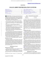
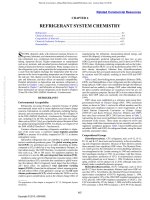
Fig. 1 Refrigerated Cargo Container
VEHICLES
Vehicles used for temperature-controlled transport are similar in
construction and outward appearance to those in general freight service, but have three fundamental differences: they have (1) insulation that is usually foamed in place, (2) provisions for conditioned
air circulation through and around the cargo, and (3) machinery for
cooling and/or heating. A brief description of the four main vehicle
types follows.
Cargo containers are usually 2.4 m wide, 2.4 to 2.9 m high, and
6.1 or 12.2 m long (Figure 1). They have hinged doors in one end
for cargo loading and other access to the interior. The machinery
comprises the opposite end, so it must also provide structural rigidity and insulation. As shown in Figure 1, containers have standardized corner fittings to secure them to vessels, railway cars, and
highway vehicles. Standards also govern their exterior dimensions.
(See ANSI Standard MH5.1.1.5 and ISO Standard 668.)
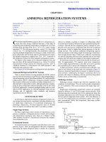
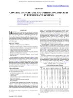
Railway refrigerator cars are insulated boxcars, usually 15 to
20 m long (Figure 2). As illustrated, they may have a machinery
compartment at one end.
Trailers range in size from 2.4 to 2.6 m wide, 3.7 to 4.1 m high,
and 7.3 to 16.8 m long. Their doors are usually hinged, but they may
have insulated roll-up doors if used for multistop delivery service.
Some include a curbside door in addition to rear doors. Several interior compartments for different temperatures may be provided by an
insulated bulkhead to separate the different zones. For hanging
uncut meat, overhead rails are used. Specially designed trailers riding on railway flat cars are quite common. Another design can be
mounted directly on specially configured railway bogies and pulled
by a locomotive in a train of similar trailers.
As with ordinary trucks, those built for temperature-controlled
duty come in a wide variety of designs and sizes. Their bodies may
The preparation of this chapter is assigned to TC 10.6, Transport Refrigeration.
Fig. 1 Refrigerated Cargo Container
have insulated hinged or roll-up doors on the sides and rear. Truck
bodies also may have several interior compartments for different
temperatures, similar to trailers, with an insulated bulkhead separating the different zones. Smaller vehicles may include a refrigeration
compressor as an engine-driven accessory (see Figure 7).
VEHICLE DESIGN CONSIDERATIONS
Insulation and Vapor Barrier
Envelope design factors to be considered are similar to those for
stationary refrigerated facilities, and include the following:
• Extremes of exterior conditions: temperature, relative humidity,
wind, and solar effect
• Desired interior conditions: temperature and relative humidity
• Insulation properties: thermal conductivity, moisture permeability
and retention, chemical and physical stability, adhesion, uniformity of application, fire resistance, cost of material and application, and presence of structural members
• Infiltration of air and moisture
• Tradeoffs between construction cost and operating expense
When applied to refrigerated vehicles, these five factors are complicated by others unique to transportation. Exterior dimension constraints are imposed by domestic or international standards and
regulations, and shippers want maximum cargo space (which limits
insulation thickness) and minimum tare weight. The frequency and
duration of door openings may be considerable. Long trips at highway or railway cruising speeds affect infiltration. Physical deterioration from the shock and vibration of travel and cargo shifting is likely.
Also, there is potential for damage to insulation and vapor barriers
from vehicle accidents and cargo handling mishaps.
25.1
Copyright © 2010, ASHRAE
This file is licensed to Abdual Hadi Nema (). License Date: 6/1/2010
25.2
2010 ASHRAE Handbook—Refrigeration (SI)
Licensed for single user. © 2010 ASHRAE, Inc.
Fig. 2
Mechanical Railway Refrigerator Car
Fig. 2 Mechanical Railway Refrigerator Car
Closed-cell foamed-in-place insulation, such as polyurethane,
is generally recommended to achieve an approximate thermal
conductivity k of 0.022 W/(m·K). It also helps limit air and water
vapor infiltration. Buyers often specify the UA or maximum heat
transfer rate, usually at 38°C and 50% rh outside and –18°C inside,
expressed as W/K for the entire vehicle.
Environmental considerations affect and are affected by vehicle
insulation and vapor barrier choices. Mandated changes to insulation frothing agents with little or no adverse environmental impact
may increase insulation k value, and moisture permeability and
retention. Chemical and physical characteristics such as adhesion,
durability, and stability may also be degraded. Because reduced
insulation effectiveness increases energy use, it adds to air pollution and global warming concerns. Finally, the potential for materials recycling at the end of useful vehicle life must be considered.
Cargo containers usually have polyurethane insulation at 75 mm
thickness in walls and floors, and 100 mm in ceilings. Rail cars often
use 75 to 150 mm in walls, and 125 to 200 mm in floors and ceilings.
Trailers and trucks generally use 35 to 100 mm in walls, floors, and
ceilings for frozen loads, and 25 to 65 mm in walls, floors, and ceilings for nonfrozen loads. Vehicle front walls are sometimes thicker
to resist cargo shifting and support equipment.
As mentioned previously, exterior dimensions are restricted and
shippers want maximum cargo space. Increasing insulation thickness from 75 mm to 100 mm in a 12 m long trailer decreases cargo
space by 2.8 m3, or about 4%. However, the vehicle’s UA will
improve, affecting equipment selection and improving operating
economy. This exemplifies the need to regard the vehicle and its
equipment as a system.
Floors in all vehicles must support cargo and cargo-handling
equipment. They frequently include rigid polystyrene or polyurethane foam to eliminate beams. Floors must be watertight and
joined to walls to exclude water from insulation; a skirt bonded to
the floor and extending at least 150 mm up walls may be needed to
control water running down walls and collecting on the floor. Floor
drains, if used, must be trapped or capped to prevent infiltration of
outside air.
Infiltration of moisture and air is affected by the integrity of a
vehicle’s exterior surfaces (usually sheet metal with riveted joints).
The molded glass-fiber-reinforced plastic sometimes used for truck
and trailer exteriors is quite effective. There is some experimentation with composite materials for cargo container bodies. Inside, it
is common to use a vapor barrier, such as aluminum foil coated with
plastic binder and sealed at joints. Integrity of foamed-in-place insulation (the absence of voids and breaks) is also important. Other
physical contributors include the effectiveness of door gaskets and
sealing around all exterior-to-interior penetrations. Operational factors are vehicle travel speed and the frequency and duration of door
openings.
Purchasers of new refrigerated vehicles may require air leakage
tests. Purchasers’ criteria for these tests vary, depending on vehicle
size and intended use. A cargo container for modified-atmosphere
service (see the discussion on Controlled and Modified Atmosphere
in the Equipment section) must be especially tight. The purchaser
may specify that air pressure in a 12 m long container drop from
750 to 500 Pa in not less than 8 min, for a leakage rate of approximately 1.4 m3/h. A 14.6 m trailer for general refrigeration service
may be tested at 125 Pa with a leakage limit of 3.4 m3/h.
Infiltration into insulated vehicles occurs even when they are stationary, probably because of stack effect caused by the inside-tooutside temperature difference. The infiltration driving force for a
vehicle 2.4 m high with a 55 K difference is about 7.5 Pa (Phillips
et al. 1960). Openings with an aggregate area of 645 mm2 each at the
This file is licensed to Abdual Hadi Nema (). License Date: 6/1/2010
Cargo Containers, Rail Cars, Trailers, and Trucks
top and bottom allow infiltration of about 3.4 m3/h if assumed to be
thin-plate orifices.
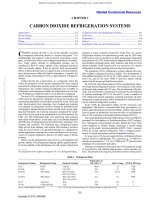
Eby and Collister (1955) discuss the infiltration load from air
entering through cracks in the front of a moving vehicle. The ram
air pressure is 300 Pa at 80 km/h, and an exposed 645 mm2 opening
can allow 32.6 m3/h of air to enter. At ambient conditions of 38°C
and 50% rh and a vehicle temperature of –18°C, the extra infiltration load is approximately 1115 W. Figure 3 illustrates heat gain
into a –18°C vehicle resulting from infiltration of ambient air at
various conditions.
Air Circulation
Licensed for single user. © 2010 ASHRAE, Inc.
To avoid spoilage during transport,
• Surround the cargo with a flow of conditioned air sufficient to
remove heat that enters the vehicle by conduction and infiltration.
To do this, interior surfaces must have channels for flow of conditioned air. There may be space between the top of the cargo and
the ceiling, or flexible duct(s) in that space, or a fixed duct (false
ceiling). Walls may have batten strips, or channels formed into the
wall surfaces, or fixed ducts (false walls). The floor may have
fixed longitudinal T-bars or “hat” sections, or movable racks.
• For commodities that respire or require in-transit cooling (e.g.,
fresh fruits, vegetables, flowers), provide an adequate flow of conditioned air between and through packages. This process relies on
the air circulation ability of the equipment (see Equipment Selection in the section on System Application Factors), and commodity loading practices (see Vehicle Use Practices in the section on
Operations).
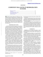
Conditioned air may enter the cargo space over the top of cargo
(normally used in rail cars, trailers, and trucks), or under the cargo
(normally used in cargo containers). Figure 4A shows an example of
a trailer with a top air delivery system. Air gaps between the cargo
allow conditioned air to flow sufficiently around the load and along
the side. Figure 4B shows an example of a cargo container system
Fig. 3 Heat Load from Air Leakage
25.3
with a bottom air delivery system. In a bottom air delivery system,
it is important to maintain air pressure under the load. Respiring
commodities should be packed in boxes with aligned top and bottom vent holes so conditioned air can flow through and remove heat.
Proper loading technique is critical to maintaining good air circulation around the cargo to prevent spoilage. For additional information about loading techniques, see Ashby (2000).
Equipment Attachment Provisions
All components must be securely fastened to the vehicle to resist
shock, vibration, and vandalism. Vehicle-to-equipment interfaces
must have structure capable of secure support under all conditions
of dynamic loading caused by vehicle travel and equipment operation (e.g., engine and compressor vibration). Suitable fastening provisions (mounting holes, studs, or captive nuts) are needed. Wall
openings for equipment, which may be large (e.g., the entire front
wall of cargo containers), must have provisions to limit infiltration,
using gaskets or other sealing methods.
Sanitation
Vehicle internal cleanliness is enhanced by eliminating interior
crevices where fungi and bacteria can grow, and by using surfaces
that tolerate cleaning materials such as hot water, disinfectants,
detergents (including harsh cleaning solutions), and metal brighteners. Vehicle interiors should enable access to equipment components
exposed to conditioned air (e.g., fans, cooling coils, and condensate
pans) for periodic cleaning.
EQUIPMENT
Mechanical Cooling and Heating
Refrigerated cargo containers typically have unitary equipment
that comprises the entire front wall of the container. The refrigeration unit depth is approximately 400 mm and provides structure and
insulation to the container front wall. Figure 5 illustrates a typical
unit. The equipment has a vapor compression refrigeration system
and uses an external source of electricity for its compressor and fan
motors, resistance heaters, and operating controls. It usually uses
bottom air delivery, as shown in Figure 4B. The unit may have a
Fig. 4 Air Delivery Systems (A) Top and (B) Bottom
Fig. 3 Heat Load from Air Leakage
Fig. 4 Air Delivery Systems (A) Top and (B) Bottom
This file is licensed to Abdual Hadi Nema (). License Date: 6/1/2010
25.4
2010 ASHRAE Handbook—Refrigeration (SI)
Licensed for single user. © 2010 ASHRAE, Inc.
Fig. 5 Container Refrigeration Unit
Fig. 5
Container Refrigeration Unit
Fig. 6 Trailer Unit Installation
Fig. 7 Small Truck Refrigeration System
Fig. 6 Trailer Unit Installation
detachable diesel engine-generator set (with integral fuel tank)
accompany it while traveling by land.
Rail cars may have field-installed components. A three-phase ac
diesel engine-generator set, condensing unit, and refrigerant and
electrical operating controls are usually located in a machinery
compartment at one end of the car. An evaporator fan-coil package,
or separately mounted evaporator and fan, is typically adjacent to
the machinery compartment but inside the insulated space. Electric
heaters in or under the evaporator are used for heating and defrost.
This equipment usually uses top air delivery, as shown in Figure 4A.
Fuel tanks are generally located under the car. Newer rail cars may
use end-mounted unitary equipment similar to trailers.
Trailers typically have unitary equipment that consists of a diesel
engine with battery-charging alternator, compressor, condenser and
engine radiator with fan, evaporator with fan, and refrigerant and
electrical controls. It is installed on the front of the vehicle near the
top, over an opening that accommodates the evaporator and fan, as
shown in Figure 6. Top air delivery is usually used as shown here
and in Figure 4A. The fuel tank is mounted under the trailer.
Fig. 7 Small Truck Refrigeration System
Large trucks typically have unitary equipment that is similar to
trailer equipment, but more compact. Small trucks may have unitary equipment similar to that for large trucks, or field-installed
components. The latter, as shown in Figure 7, have a truck-enginedriven compressor. Also included is a condenser and evaporator
fan-coil package. The unit is installed at the front top over an opening that accommodates the evaporator and its fan(s). (So it can be
seen in this figure, the evaporator is shown shifted rearward.) Most
This file is licensed to Abdual Hadi Nema (). License Date: 6/1/2010
Cargo Containers, Rail Cars, Trailers, and Trucks
Fig. 8 Multitemperature Refrigeration System
Fig. 8
Licensed for single user. © 2010 ASHRAE, Inc.
Fig. 9
tions
Multitemperature Refrigeration System
Examples of Common Multitemperature Configura-
25.5
space for cooling, worker safety precautions must be observed to
avoid asphyxiation hazards.
Eutectic plates are sometimes used in local delivery vehicles and
are mounted on walls, ceilings, or both, or may be used as shelves or
compartment dividers. Most have internal heat exchangers to allow
recooling from a stationary or vehicle-mounted refrigeration system
while the vehicle is not in motion.
The thermal storage effect of precooled milk or fruit juice, and
some hot liquids, can hold the commodity within satisfactory temperature limits if carried in sufficiently insulated tanks.
Heating Only
Commodities sensitive to low temperature are sometimes hauled
in insulated vehicles with heating capability only. Direct-combustion
heaters may be fueled by alcohol, butane, charcoal, kerosene, or
propane. These are hazardous and must be appropriately designed
and carefully used.
Engine-driven units, consisting of a diesel engine with batterycharging alternator, engine-coolant heat exchanger, engine-driven
fan, and operating controls, are available. They are installed on the
front of the vehicle near the top, over an opening that accommodates
the heat exchanger and fan. Top air delivery is typically used, as
shown in Figure 4A. The fuel tank is placed under the vehicle.
Ventilation
Fig. 9 Examples of Common Multitemperature
Configurations
of the refrigerant and electrical controls are usually also in this
package. The controls and fan motors receive power from the
truck’s electrical system. Top air delivery is generally used, as
shown in Figure 4A.
Trucks and trailers with multiple interior compartments at different temperatures require a multitemperature refrigeration unit. A
moveable insulated bulkhead typically separates the different compartments, and remote parallel evaporators are connected to the
main refrigeration unit, which is connected to the front wall. Figure
8 shows a typical trailer multitemperature system with two zones.
With a multitemperature truck or trailer, many different configurations can be set up based on the placement of the remote parallel
evaporator and dividing bulkhead. Figure 9 shows some common
two- and three-zone configurations. Zone compartment size is limited by the cooling and heating capacity required for each zone.
Over- or undersizing the compartment can lead to poor temperature
control. The total cooling (or heating) load of the multiple compartments cannot exceed the main refrigeration unit’s gross capacity.
Storage Effect Cooling
Although mechanical cooling now dominates, stored thermal
energy is still occasionally used for transport of commodities.
Ice was the primary cooling means in rail cars for 100 years, but
was phased out in most developed nations during the latter half of
the twentieth century. When used, it is put in bunkers at each end of
the car, and cargo cooling occurs by natural convection, or by forced
convection using battery-powered fans that may be charged by axledriven generators. Ice is still sometimes spread on top of rail car and
trailer loads to supplement mechanical refrigeration to remove field
heat, or as an enhancement to mechanical refrigeration.
Solid carbon dioxide (dry ice) is sometimes used in small insulated boxes of very cold commodity. Liquid CO2 or nitrogen, when
used in vehicles, may be expanded directly into the cargo space.
Alternatively, CO2 is evaporated in a heat exchanger that cools
cargo compartment air, and the gas is exhausted outside. The fluids
are carried in storage vessels located in or outside the refrigerated
space. Note: when these fluids are directly expanded into the cargo
Ventilation for temperature control is usually accomplished by
adjusting the opening of small doors at the front and rear to establish
a flow of outside air through the vehicle. It is strictly limited by outdoor conditions. Ventilation is sometimes used with mechanical
refrigeration to reduce the concentration of ripening gases in fresh
commodities (see the section on Operations).
Controlled and Modified Atmosphere
The benefits of controlled-atmosphere (CA) and modifiedatmosphere (MA) transport are proportional to the duration of
commodity exposure, so these supplements to mechanical refrigeration tend to be used when shipboard travel is involved. For
further information, see Control of Atmospheric Chemistry in the
Operations section.
Seagoing cargo container equipment sometimes has CA capability incorporated. Typical systems sense CO2 and O2 and are able to
boost N2 and/or CO2 concentration in the cargo space, depending on
commodity needs. Nitrogen levels are usually raised by passing a
small flow of outside air through a N2 separator, and venting O2 and
trace gases outside the vehicle. A supplemental supply of CO2 is
required to increase its concentration.
For short trips, or when replenishment is practical, MA may be
used. It involves injecting an appropriate gas into the vehicle or into
special commodity packaging, so it does not affect equipment
design.
Control Systems
Equipment control system functions normally include temperature control, defrost, and safety provisions. Cargo space return or
supply (and sometimes both) air temperatures are monitored and
thermostatically controlled. In addition to off/on cooling and
heating, more sophisticated systems include gradual capacity
modulation to achieve a commodity temperature closer to the set
point. Evaporator coil defrost may be initiated by sensing system
performance parameters (e.g., evaporator airway pressure differential) or at timed intervals, and is usually terminated by sensing
temperature on some part of the evaporator. Safety provisions
essential to avoiding equipment damage and hazards to people are
also incorporated.
Equipment control system functions may also include the
following:
This file is licensed to Abdual Hadi Nema (). License Date: 6/1/2010
25.6
• Monitoring and displaying important operating parameters such
as return air temperature
• Logging a detailed record of equipment performance during trips
• Providing alarms if unacceptable conditions occur
• Monitoring probes in the cargo space (e.g., for commodity pulp
temperature)
• Stopping and starting engine-driven equipment, depending on the
need for cooling or heating, to improve fuel economy
• Adjusting system capacity to match engine power capability during cargo space temperature pulldown and at different ambient
temperatures
• Monitoring and controlling cargo space atmospheric chemistry
and relative humidity
Many of these control system functions are made practical by
microprocessors. They enhance equipment response to varying
operating conditions, such as ambient temperature. Their memory
capability facilitates pretrip equipment operational checks, and
enables tracking of equipment performance and analysis of possible
malfunctions. Also, microprocessors can be used with radio telemetry to enable a central location to monitor thermostat set point,
return and supply air temperature, operating mode, and alarm status.
Licensed for single user. © 2010 ASHRAE, Inc.
EQUIPMENT DESIGN AND SELECTION FACTORS
This information is intended as a source of typical transportation
duty guidelines for equipment design engineers, and for persons who
select, specify, or apply this equipment. Specific applications may
have more or less severe requirements.
2010 ASHRAE Handbook—Refrigeration (SI)
Table 1 Typical Peak Shock Levels
Peak Shock, by Axis, g a
Vertical
Longitudinalb
Lateralc
Containers
Highway
Rail (on flat car)
9
7
2
7
4
3
Railway cars
Standard draft gear
Cushioned
9
7
14
7
5
3
Trailers/trucks, highway
9
2
4
Trailers, railway
On flat car
Bimodald
3
9
6
6
2
5
Equipment
aAcceleration
cCross-wise
bParallel
of gravity, 9.8 m/s2.
to direction of travel.
dSee
of vehicle.
Vehicles section.
Vibration criteria are difficult to establish because of the many
variables involved. For example, vehicle speed and road characteristics have an input that varies widely. Equipment manufacturers
often have criteria based on their testing and experience.
It is good design practice to avoid equipment natural frequencies
of 10 Hz or less (these are typical vehicle wheel rotation and suspension inputs). Also, equipment should not have natural frequencies close to the equipment engine’s firing frequency, compressor’s
pumping frequency, or frequency of any of its rotating components
(see the section on Qualification Testing).
Time
Time is a design factor for some components. Two examples
illustrate how it affects the objective of producing a robust system:
(1) an oversized refrigerant filter-drier is often used because there
may not be enough time for thorough refrigeration system evacuation during emergency service operations; moisture remaining in
the system can be removed by one or more changes of a large filterdrier; and (2) a large engine oil reservoir reduces the frequency of
oil level inspections and extends time between oil changes without
sacrificing engine reliability.
Shock and Vibration
Shock and vibration are primary design concerns because equipment travels with the vehicle it serves, often includes an internal
combustion engine, and may be subjected to occasional rough handling. Most system components are affected, but particular attention
must be given to design of
•
•
•
•
•
•
•
•
•
Structural frames
Heavy component attachment
Shock and vibration isolation devices
Finned-tube heat exchangers
Refrigerant piping (including capillaries) and its supports
Refrigerant filter-driers
Wiring supports and routing
Electronic control devices
Air impellers
Table 1 provides general guidance to the engineer in establishing design load factors for structural calculations. Impacts of these
magnitudes may occasionally occur during vehicle travel. The
resulting forces transmitted to the equipment may be amplified or
attenuated by the response of the intervening vehicle structure.
Also, adjustment may be needed for local conditions (e.g., highways in very poor condition). Although g-levels under such conditions may be only slightly higher, the frequency of occurrence may
be several times greater. Table 1 is based on data in four reports prepared by the Association of American Railroads (AAR 1987, 1991,
1992a, 1992b).
Ambient Temperature Extremes
Ambient temperature is a primary design consideration because
equipment must be able to start, run, and perform under conditions
that may include summer desert, summer tropical, and winter neararctic. Many items are affected, but particular attention must be
given to design of
• Heat exchangers using ambient air as a heat sink
• Other components dependent on ambient air for cooling, especially motors, alternators and generators, and electronic devices
• Systems relying on heat of refrigerant compression for heating or
evaporator defrost
• Components that include elastomers and plastics, whose physical
properties may be degraded
• Engine cranking motors, to account for engine oil viscosity
increases and battery voltage decreases during cold weather
Typical ambient temperature maximum and minimum values
for several geographic areas are shown in Table 2 as a guide for
equipment design. Some vehicles (e.g., cargo containers) may
travel anywhere, and their equipment should be designed for
global extremes. Others, such as delivery trucks, usually have
equipment designed for local conditions only. Engine starting
below –30°C may be difficult and require special procedures, but
equipment operation can be required to heat the vehicle at very
low ambient temperatures.
The values in Table 2 are very general for vehicle equipment
operation in the areas considered. Consult Chapter 14 of the 2009
ASHRAE Handbook—Fundamentals for more specific data. Caution is required when using climatic design information because (1)
more extreme temperatures may be encountered at locations in the
region that are some distance from the station where data are taken,
and (2) higher transient values of 55°C or more may occur because
of recirculation in sheltered areas or heat rejected from other
nearby sources (see the section on Safety).
This file is licensed to Abdual Hadi Nema (). License Date: 6/1/2010
Cargo Containers, Rail Cars, Trailers, and Trucks
Table 2
Ambient Temperatures for Equipment Design in
Several Geographical Regions
Asia
North
Europe Mideast America Tropics
Global
Maximum, °C
50
45
50
50
45
50
Minimum, °C
–40
–35
–35
–40
0
–40
Licensed for single user. © 2010 ASHRAE, Inc.
Other Ambient Design Factors
Precipitation, such as snow, hail, rain, and freezing rain, affects
electric motors, electrical component enclosures, and cable connections.
Sea water, salt-laden sea air, and wintertime road salt tend to corrode metal parts, including electric motors, compressors, and electrical enclosures and cable connections. Salt also affects finned-tube
heat exchangers, air impellers, fasteners, structural frames, and
sheet metal parts.
Air pollutants (e.g., sulfur dioxide in diesel engine exhaust of the
vehicle and equipment) combined with atmospheric moisture can
also contribute to degradation of metals, especially aluminum or
copper-finned heat exchangers.
Interior air quality is also important. Some materials, including
plastics and elastomers, may emit chemical odors that adversely
affect the taste and smell of certain foods. Their use in parts exposed
to conditioned air should be avoided. British Standards Institute
(BSI) Standard 3755, known as the butter taint test, may be used to
check this aspect of a material’s suitability.
Dirt and debris are common along highways and railways and
inside cargo spaces; insects and fluff from vegetation are also found.
Equipment designs must exclude these materials from critical components where possible, and include provisions for essential cleaning in both vehicles and equipment.
Solar radiation is unavoidable. Some components may be
affected by ultraviolet radiation, including paint, plastics, and elastomers; some may also be sensitive to heat. Solar radiation also contributes to the cooling load (see Load Calculations in the section on
System Application Factors).
Vandalism and theft can occur, and are difficult to thwart. Among
the concerns are storage batteries, electrical cables, and other components with obvious salvage value.
Equipment to be used internationally may have to meet antismuggling requirements of the TIR Handbook (UN 2007). For
example, ventilation (outside-air) ports in cargo container units
include sturdy screens.
Operating Economy
This is a complex consideration that includes reliability, serviceability, and fuel or power consumption.
Equipment should be reliable because
• It may be preserving a high-value commodity.
• It often operates unattended during trips.
• It frequently travels far from knowledgeable service technicians,
repair parts, and supplies of refrigerant and other operating fluids.
Laboratory and field experience must be combined to demonstrate the durability of operating components; the ability of the
system to start, run, and perform under all expected ambient conditions; and structural integrity.
Good equipment serviceability is important for the same three
reasons. Components and assemblies should be designed for easy
access. This is important for testing and trouble analysis, routine
maintenance, and repair or replacement of components.
Another factor peculiar to transportation refrigeration service is
the availability of knowledgeable service technicians, repair parts,
and supplies (e.g., suitable fuel; the exact refrigerant for which the
25.7
system is designed; engine coolant; and lubricants specified for the
compressor, engine, and other components).
Fuel (or power) consumption is affected by the thermodynamic
and mechanical efficiencies of engines, motors, compressors, and
power transmission devices. Thermodynamic performance of condensers and evaporators has a major role, as do system provisions
for part-load operation. Aerodynamic efficiency of air impellers and
related flow paths has an effect, too.
Airborne Sound
Sound may be a concern when residential and commercial areas
abut or government-imposed sound limits exist. Design and selection considerations include using the following:
• Engines, compressors, and air impellers that are inherently relatively quiet
• Acoustical treatments and sound attenuation features that are
durable and likely to remain in use
Safety
Safety in transport equipment is of concern because cargo handlers, vehicle operators, and service technicians are often close to
the equipment. Also, at times the general public may be near refrigerated vehicles. Although there are no known safety codes specifically for transport equipment, those mentioned in this section are
sufficiently general in scope to apply, or good engineering practice
suggests their use for guidance.
All potentially dangerous parts, including fans, belts, rotating
parts, hot surfaces, and electrical items, require appropriate guards,
enclosures, and/or warning labels. Labels should emphasize universally understandable graphics; suitable designs can be provided by
the International Organization for Standardization (ISO) or similar
groups.
Refrigerant pressure vessels must comply with applicable safety
codes; some common codes are listed here:
• American Society of Mechanical Engineers Boiler and Pressure
Vessel Code, Section VIII (ASME 2004), for vessels larger than
152 mm inside diameter
• European Committee for Standardization (CEN) Pressure Equipment Directive 97/23/EC
• CEN Standard EN 378-2:2008
• Underwriters Laboratories (UL) Standard 1995, for vessels of
152 mm or less inside diameter
Refrigeration system design pressures should account for
worst-case temperature extremes for any intended application of
equipment. Because the presence of some liquid is likely, either by
design or from excess refrigerant in the system, saturation pressures are used.
Under nonoperating conditions, usually 66°C (saturation) is
used for low and high sides, based on new product shipping experience. Vehicles standing still in the sun without wind should meet
this criterion, as well. Note: shipping package design and storage
practices must anticipate potential excessive temperature hazards.
For example, equipment covered with plastic shrinkwrap may
experience temperatures greater than 66°C when left in direct sunlight.
While operating, the low side is unlikely to exceed the nonoperating criterion. The high-side criterion of 66°C (saturation) is based
on the nonoperating value because the worst-case high-side value,
from ASHRAE Standard 15-2007, par. 9.2.1(c), is lower. For
example,
• 55°C Europe worst case: Sevilla, Spain at 38°C 1% db
• 60°C North America worst case: Yuma, AZ at 43°C 1% db
• 63°C Mideast worst case: Kuwait, Kuwait at 46°C 1% db
This file is licensed to Abdual Hadi Nema (). License Date: 6/1/2010
25.8
2010 ASHRAE Handbook—Refrigeration (SI)
High-side saturation temperature excursions above 65°C can
result from the 55°C (or more) transients cited in the Ambient Temperature Extremes section. For example, 68°C is sometimes used
for trailer equipment.
The choice of over-pressure protection in the high side, as for a
liquid receiver, also affects design pressure.
Licensed for single user. © 2010 ASHRAE, Inc.
Example 1. What design pressures are required if a pressure-relief device
(valve or rupture disk) is used, or if a fusible plug is used? The highest
normal pressure for a R-134a system high side, assuming 68°C transient
exposure, is 1938 kPa (gage). The critical pressure for R-134a is
3958 kPa (gage).
Solutions:
Pressure-relief device: The recommended 25% margin between
relief pressure and the highest normal pressure (to avoid accidental discharge) raises minimum relief pressure from 1938 to 2420 kPa (gage).
Therefore, a design pressure of 2450 kPa (gage) is appropriate. Pressure
vessel testing at 1.25 or 1.5 times design pressure is required by major
safety codes.
Fusible plug: The design pressure must be 1938 kPa (gage) or
greater. So, a design pressure of 1965 kPa (gage) is appropriate. If a
fusible plug with a nominal setting of 78°C is chosen, the corresponding nominal release pressure is 2441 kPa (gage). Some codes (e.g., UL
Standard 1995) require pressure vessel testing at 2.5 times the nominal
release pressure or the critical pressure, whichever is less; in this example, 2.5 times release pressure (in kPa) would be used.
Safety codes (e.g., ANSI/ASHRAE Standard 15-2007) require
overpressure protection such as a relief valve, rupture disk, or
fusible plug. Also required is a pressure-limiting device (i.e., a
high-pressure switch to stop compressor operation). Overpressure
protection design decisions must consider possible regional or
local regulations that reflect environmental concerns. Rupture-disk
discharge to atmosphere may be prohibited in some areas unless in
series with a relief valve. Fusible plugs may be prohibited in some
areas unless connected to the low-pressure side.
QUALIFICATION TESTING
This section provides an overview of testing usually done by
equipment manufacturers to determine whether equipment meets
operating design criteria and performs satisfactorily in the transportation environment. Prospective users may wish to be guided by evidence of successful completion of appropriate tests, or may wish to
consider special testing of their own.
Operational tests are done to establish the ability of equipment to
provide satisfactory control of temperature in a typical vehicle, especially at set points between –1 and 16°C. Tests normally include
cooling and heating, with ambient temperatures above, at, and below
each set point. Operation over the entire range of ambient and internal temperatures expected for the intended vehicles is also tested.
Psychrometric testing is appropriate because cargo space relative
humidity affects nonfrozen commodity desiccation. Desiccation is
limited by keeping the evaporator surface temperature as high as
possible by its thermodynamic design and by refrigeration capacity
control methods. In some equipment, additional control is achieved
by sensing relative humidity and atomizing water into the conditioned air stream as needed to maintain the desired level for commodity storage.
It is also necessary to verify operation of other equipment functions, such as defrost effectiveness and evaporator fan performance
(static pressure versus flow). If controlled atmosphere is an equipment option, its effectiveness may need to be checked.
For equipment rating purposes, refrigeration capacity is normally determined at the following conditions:
• 38°C ambient in North America, and 30°C in Europe
• 2, –18, and –29°C cargo space (return air) in North America, and
0 and –20°C in Europe
Capacity may be certified to meet ARI Standard 1110 or other
industry standards. Most qualification testing programs also include
establishing capacity at other conditions.
Heating capacity (if not electric resistance) is usually, as a minimum, tested at –18°C ambient and 2°C cargo space (return air).
Shock and vibration qualification demonstrates that equipment
meets guidelines presented in the Equipment Design and Selection
Factors section. Search for natural frequencies of 10 Hz or less, and
for any that are close to the firing frequency of the equipment’s
engine, pumping frequency of the compressor, or frequency of any of
its rotating components. This testing may be done on laboratory apparatus that shakes equipment in each of its three primary axes. Endurance testing usually follows, using an amplitude and frequency
spectrum based on field experience. A special test for cargo container
equipment imposes typical lateral (racking) and end-loading forces.
Field trials are essential; they usually take several months, and are followed by disassembly and thorough inspection. Some redesign may
be needed; testing should be repeated as needed to confirm its success.
Testing at extremes of ambient temperature (and sometimes relative humidity) is usually done on major mechanical and electrical
components by their suppliers (including engines, compressors,
motors, alternators, generators, solenoids, and electronic devices).
It is also done on complete equipment in test chambers able to operate over the temperature ranges expected for both high and low
sides. Of particular interest is the ability of equipment to start and
run at ambient and cargo space extremes, and evaporator defrosting
performance.
Qualification for other ambient design factors generally includes
the following:
• Rain testing is usually done by component suppliers on items
such as electric motors. It is also done on complete equipment to
check integrity of electrical cabinets and cable entries.
• Components susceptible to ocean-environment corrosion, especially for cargo containers, are laboratory-tested in specially
designed salt-spray apparatus.
• Visual inspection and experience-based judgment are usually
used for concerns such as potential for clogging with dirt and
debris, and susceptibility to vandalism and theft.
• Items exposed to sunlight, including elastomers, plastics, labels,
and paints, are laboratory-tested for ultraviolet resistance.
SYSTEM APPLICATION FACTORS
As noted in the introduction, users of this information are urged
to regard the vehicle and its equipment as a system. This section provides guidance for that design effort. Three steps, discussed in the
following sections, are recommended.
Load Calculations
The objective of load calculations in this application is to determine average conduction and infiltration loads per hour. Familiarity
with Chapter 24 is helpful.
The vehicle’s heat transfer factor (UA) should be determined. If
more than one insulation system is being considered (e.g., several
thicknesses), there will be a UA factor for each. This information is
normally available from the vehicle manufacturer. It may be calculated with guidance from Chapter 24 and confirmed (or determined)
by test (TTMA 2007). Multitemperature applications separate compartments with an insulated bulkhead, and its heat transfer factor
must also be determined and considered when performing a load
calculation.
Typical vehicle travel time (hours) is needed. For long hauls, add
the vehicle’s stationary time at each end while loaded with the
equipment operating. The time for short hauls is usually a typical
working day.
This file is licensed to Abdual Hadi Nema (). License Date: 6/1/2010
Licensed for single user. © 2010 ASHRAE, Inc.
Cargo Containers, Rail Cars, Trailers, and Trucks
Determine the range of average ambient temperatures the vehicle
is likely to encounter (see Ambient Temperature Extremes in the
section on Equipment Design and Selection Factors) The range of
commodity types and temperatures the vehicle is likely to encounter
must also be known.
Solar radiation may be approximated using data in Table 3 of
Chapter 24. For example, assume the vehicle roof and one side are
exposed to the sun. Divide the sum of the products of areas and
temperatures by the total area to get an adjusted ambient temperature. (If this were included in Example 2, the ambient temperature
would be about 1.7 K higher, increasing conduction and infiltration
about 6%, and total load about 4%.)
Infiltration through the vehicle body and closed doors is usually
included in the UA value, although infiltration during door-open
time is not. This is a significant consideration for delivery vehicles;
estimates may be made using information from vehicle or equipment manufacturers, or it may be calculated using Chapter 24. For
multitemperature applications, infiltration through the insulated
bulkhead needs to be considered. The amount of infiltration
depends on how effective the seal between the bulkhead and walls
is, as well as what type of floor is used in the vehicle. Channel
floors, which promote airflow through the vehicle body, increase
infiltration between compartments in a multitemperature application. Common aluminum floors provide a conduction path for heat
to travel between different compartment zones.
Vehicle aging effects should be considered, because the vehicle’s
ability to protect low-temperature commodities decreases with
time. Insulation and door seal deterioration can increase the vehicle’s UA by 25% or more in vehicles older than 3 years.
Cooling load calculations in Example 2 include commodity temperature pulldown and heat of respiration. Both of these vary widely
with the type of commodity and its treatment before loading into the
vehicle. Some commodities (e.g., frozen goods and meat) have no
heat of respiration. Recommended practices include precooling or
preheating the vehicle to bring its interior surfaces to the planned
thermostat setting. This example does not address minor loads associated with cooling (1) air not displaced by the commodity and (2)
its packaging materials; both have relatively low mass and poor
thermal conductivity.
Example 2. Determine the conduction and infiltration load, commodity
temperature pulldown load, commodity heat of respiration, total load,
and average load for the following shipment:
Vehicle UA factor: 82 W/K
Vehicle travel time: 72 h (3 days)
Assumed average ambient temperature: 29°C
Initial average commodity temperature: 4°C
Final average commodity temperature: 1°C
Assumed average commodity temperature en route: 3°C
Thermostat setting temperature: 2°C
Commodity: Elberta peaches
Quantity: 17 000 kg
Specific heat above freezing: 3.8 kJ/(kg·K) (from Table 3 of Chapter 19)
Heat of respiration at 3°C): 16.1 mW/kg (from Table 9 of Chapter
19, interpolated)
Solutions:
Conduction and infiltration load (82)(72)(3600)(29 – 2) = 574 MJ
Commodity temperature pulldown load
(3.8)(17 000)(3) = 194 MJ
Commodity heat of respiration (0.016)(17 000)(72)(3600) = 71 MJ
Total load for trip = 839 MJ
Average load = (839)(1000)/[(72)(3600)] = 3.24 kW
Note: One vehicle insulation system was assumed in this example; if several are to be compared, iterations with the different UA
factors are required.
If cold-weather travel is likely, do a similar calculation for the
heating load. In this calculation, average ambient temperature
25.9
should ignore solar radiation. Commodity temperature pulldown
load may be nil. Heat of respiration of the commodity reduces the
total and average loads.
Equipment Selection
Selection of equipment from manufacturer’s product data begins
with matching its cooling and heating capacity to new vehicle
needs, as determined by load calculations. It may include consideration of aging effects on vehicle UA (see the note following Example 2), and equipment cooling and heating capacity.
Also important is the equipment’s ability to properly control
cargo space conditions, especially temperature. If relative humidity
and/or atmospheric chemistry control options are being considered,
their effectiveness needs review.
Microprocessors, multiple temperature sensors, and sophisticated equipment capacity controls allow close control of air temperatures, some to ±0.3 K of desired temperature. Depending on the
level of system sophistication, it is possible to control either return
or supply temperature, or both. Maintaining suitable return air temperature is essential for all commodities. Control of supply air temperature helps prevent freezing damage to commodities such as
fruits and vegetables.
Evaporator fan performance affects control of cargo space temperature, and to some extent, cargo space relative humidity. Airflow
should be adequate to ensure that the commodity is surrounded by
air at the proper temperature, and to minimize the supply-to-return
air temperature difference. Fan static pressure must be sufficient to
force air through the distribution system and cargo. Also, the evaporator may be partially frosted, so fans that can sufficiently move air
with a high amount of static air pressure are needed.
Evaporator defrost effectiveness should be judged under frozen
load conditions. It must be initiated when needed and must be thorough, to avoid ice build-up on the evaporator.
Details of vehicle selection are beyond the scope of this chapter,
but it should be guided by the section on Vehicle Design Considerations. Three sections under Equipment Design and Selection Factors also affect vehicle selection: Shock and Vibration, Ambient
Temperature Extremes, and Other Ambient Design Factors.
Operating economy data for life-cycle cost analysis should be obtained during selection for both the vehicle and equipment. Some of
these data (e.g., fuel or power consumption at various operating conditions) may be available from manufacturers. Some, such as annual
cost of emergency service, preventive maintenance, repair parts, and
supplies, come from user records and experience. Other data, such as
cost of fuel or power, may have to be forecasts.
Owning and Operating Costs
Chapter 36 of the 2007 ASHRAE Handbook—HVAC Applications discusses this topic in detail for HVAC systems, and its
contents may be adapted for vehicles and equipment used for transport of commodities. Table 1 in that chapter can be modified to suit.
Item I is the total of vehicle and equipment cost. Item V requires
deleting factors that do not apply. Other factors peculiar to the transportation business may need to be added to either owning or operating costs. Once established for a particular vehicle-equipment
combination, calculations may be replicated for tradeoff comparisons of vehicle and equipment options, such as insulation thickness,
fuel economy, and vehicle revenue.
Some cost comparison of vehicle and equipment choices is usual
in procurement. Its level of sophistication may depend on one or
more of the following:
•
•
•
•
Availability of information
Size of planned procurement
Management requirements for decision making
Familiarity with engineering economic analysis techniques
Two possible cost comparison choices follow.
This file is licensed to Abdual Hadi Nema (). License Date: 6/1/2010
25.10
2010 ASHRAE Handbook—Refrigeration (SI)
Life-cycle cost analysis: See Chapter 36 of the 2007 ASHRAE
Handbook—HVAC Applications. It would include each combination of vehicle and equipment options, and have a column similar to
Table 1 in that chapter for each year of useful life. This method accounts for the time value of money.
First-year-only analysis: For each combination of vehicle and
equipment options, comparisons would be made of initial cost, estimated fuel or power cost, and expected vehicle revenue. Organizing
information as in Table 1 in Chapter 36 of the 2007 ASHRAE Handbook—HVAC Applications is useful.
OPERATIONS
Licensed for single user. © 2010 ASHRAE, Inc.
Commodity Precooling
Ideally, every commodity should be brought to its optimum storage temperature quickly and held there until it is placed in the vehicle. Otherwise, effects on commodity quality can range from slight
to significant. This topic is addressed in more detail in chapters on
food refrigeration in this volume and other publications on refrigerated transport (see the References and Bibliography).
If a commodity is loaded at a temperature above optimum, the
vehicle’s equipment will attempt to reduce it during transit (see
Example 2). If the shipping carton design and loading pattern provide good air circulation around the commodity, and if the equipment has adequate cooling capacity, eventually the commodity
temperature approaches the thermostat setting. However, any time
spent away from optimum storage temperature makes some loss of
product quality inevitable. Therefore, regular reliance on vehicle
refrigeration equipment to compensate for bad practices in precooling, storage, and loading is not recommended.
Vehicle Use Practices
Cleanliness of vehicle interiors, including conditioned air paths,
is essential to food commodity safety and quality. It avoids bacterial,
chemical, and odor contamination, and in some cases (e.g., transport of fresh meat products) may be required by government food
safety regulations. Regular cleaning and sanitizing are recommended; details appear in publications such as Protecting Perishable Foods During Transport by Truck (Ashby 2000) and Guide to
Refrigerated Transport (IIR 1995).
Precool the closed vehicle to the desired commodity temperature
before loading. In cold weather, preheat for fresh commodities. This
may take several hours under extreme ambient temperatures. However, precooling or preheating helps avoid overwhelming the equipment’s capacity and possible damage to portions of the cargo. Note:
to avoid significant frost buildup on the evaporator, do not operate
equipment in cooling mode when loading at an open, unrefrigerated
dock.
Prompt cargo transfer between refrigerated warehouses and
vehicles is important to maintenance of product quality. Ideally,
loading and unloading should be done using refrigerated dock areas.
When this is not possible, commodity movement methods and
packaging that minimize exposure to warm air (or very cold air for
fresh commodities) become very important.
Commodity loading practices are an important factor in helping
the equipment maintain good temperature distribution within the
cargo. Main points to remember include the following:
• Use packages and stack heights that avoid crushing (which blocks
airflow between packages)
• Provide spaces between packages for airflow through the load
• Leave adequate space between ceiling and cargo for airflow
• Support cargo away from walls and doors so that air, rather than
the commodity, absorbs transmitted heat
For further information, see Ashby (2000) and IIR (1995).
Commodity arrangement is important in delivery vehicles that
have frequent door openings to unload cargo. Items to be removed
at the first scheduled stop should be located close to the door(s), to
expedite unloading and minimize door-open time. Next in the
arrangement should be items for the second stop, then the third, etc.
During door-open time while unloading, it is important to minimize
air infiltration into the vehicle. Air curtains are common in delivery
transport vehicles. Vehicles with air curtains installed should have
regular maintenance to ensure that protection is adequate and damage to the air curtain is repaired quickly. For delivery vehicles without air curtains, the refrigeration unit itself should be momentarily
turned off while doors are open to minimize the amount of air infiltration. Most equipment manufacturers sell door switches with their
equipment to automatically shut down the refrigeration unit when
the door is opened and restart it when the door is closed. If no door
switches are installed on the vehicle, the equipment should be manually shut off by the operator before opening the door and restarted
when the doors are closed.
Temperature Settings
The cargo space must be held close to a temperature that helps
maintain commodity quality and provides desired shelf life at its
destination. This volume, as well as Ashby (2000) and IIR (1995),
are good sources for the recommended storage temperatures for various commodities. Because these sources draw from several sets of
research and field experience, there are minor differences in the recommendations, but using any of them (or other, similarly reliable
sources) should yield good results. Users sometimes create their
own tables of settings based on the work of others and experience
with shipments.
Thermostat settings for nonfrozen commodities must be chosen
carefully to avoid possible damage from lengthy exposure to subfreezing evaporator air discharge temperature. The following example is related to the Load Calculations example, and shows that
portions of the commodity exposed to the supply air stream could
suffer freezing damage.
Example 3. Determine the approximate supply air temperature (SAT),
at both full and reduced refrigeration capacities, for the following
shipment:
Return air temperature: 2.2°C
Refrigeration capacity: 14 070 W
Refrigeration capacity, reduced by equipment’s capacity control:
3800 W
Evaporator airflow: 1416 L/s
Approximate specific heat of air: 1.004 kJ/(kg·K)
Approximate density of air: 1.2 kg/m3
Commodity: Elberta peaches
Initial freezing point: –0.9°C
Solution:
SAT (full capacity)
2.2 – {14.07/[(1416)(1.004)(1.2)(0.001)]} = –6.2°C
SAT (reduced capacity)
2.2 – {3.8/[(1416)(1.004)(1.2)(0.001)]} = 0°C
As discussed in the section on Control Systems and Equipment
Selection, equipment with microprocessors and sophisticated capacity controls can achieve very close air (and commodity) temperature
control. Some equipment can control both return and supply air
temperatures.
Other Cargo Space Considerations
The number of days spent in a refrigerated vehicle determines
whether fresh commodities benefit significantly from ventilation, or
control of relative humidity and/or cargo space atmospheric chemistry. Because their itineraries often include lengthy sea voyages,
cargo containers are more likely to need one or more of the three following provisions.
Ventilation. Cargo container equipment may include means to
admit outside air to reduce concentration of gases, primarily ethylene
This file is licensed to Abdual Hadi Nema (). License Date: 6/1/2010
Licensed for single user. © 2010 ASHRAE, Inc.
Cargo Containers, Rail Cars, Trailers, and Trucks
and CO2, that are produced by fresh product respiration. Their outside air openings are adjustable and usually calibrated for several air
exchange rates. Some container users publish suggested rates for
various fresh products, ranging from 7 to 70 L/s. Information may be
available from local growers’ cooperatives, agricultural universities,
and similar organizations.
Other vehicles, such as trailers, sometimes have small doors in
their front and rear to admit and exhaust air as discussed in the section on Equipment. If ambient temperatures are moderate, a few
products (e.g., unripened honeydew melons) may be transported
with ventilation only.
Relative Humidity Control. Equipment, particularly for cargo
containers, may have relative humidity sensing and control capability. Lengthy trips may make humidification desirable to help limit
commodity desiccation. To maintain sanitary conditions within the
cargo space, it is essential that potable water be put in the humidifier
reservoir. Some equipment may have provisions to automatically
replenish the reservoir with condensate from evaporator defrost
operation. For further information, see Chapters 30 to 42 in this volume, Ashby (2000), and Nichols (1985).
Control of Atmospheric Chemistry. The chemistry of the cargo
space atmosphere may affect fresh product quality at its destination.
Commodity respiration, the combining of natural sugars with
oxygen, can be slowed by reducing the ambient O2 level. Increasing
the CO2 level slows respiration further, and helps prevent premature
aging. Specific combinations of gases control, and in some cases
eliminate, certain pathogens and insects. Also, texture and color can
be maintained by limiting ethylene, a natural ripening agent. Each
product has unique physiological characteristics that dictate specific
O2 and CO2 levels. Depending on travel time, monitoring and control of these levels can be critical to maintaining product quality.
Ashby (2000) only provides recommendations for berries and cherries (perhaps because most truck and trailer trips are of a few days’
duration); a 10 to 20% CO2 atmosphere is normally used as a mold
retardant.
For long hauls, especially in seagoing cargo containers, controlledatmosphere capability may be needed. As discussed in the Equipment
section, CO2 and O2 are sensed. N2 and/or CO2 concentrations in the
cargo space are then adjusted, depending on commodity needs.
On short hauls, or when en-route replenishment from a stationary
source is practical, modified atmosphere may be used. The entire
vehicle may be treated after loading, but requires a seal of plastic
film at the doorway(s), successive purging operations to drive out
much of the air, and injection of the gas treatment. Sometimes pallet
loads of commodity are sealed, evacuated, and injected with the
appropriate gas.
For further information, including advice on control settings, see
Chapters 21 and 35, Hardenburg et. al. (1990), Kader et al. (1992),
and Nichols (1985).
Maintenance
Successful operations depend on regular pretrip inspections and
scheduled maintenance. Prompt action to correct vehicle or equipment deficiencies is required. Note: all appropriate safety precautions must be taken during pretrip and scheduled maintenance work.
Proper vehicle maintenance helps ensure system effectiveness
in preserving temperature-sensitive commodities. Periodic inspection, preferably before each trip, is essential. It should include the
following:
• Attachment of equipment components: correct loose or damaged
fasteners
• Insulation, vapor barrier, and door seals: repair or replace damaged areas
• Air distribution system (ducts): repair or replace damaged parts
• Evaporator condensate outlets: clear drain lines and replace or
correct faulty air traps
25.11
• Floor drains: repair or correct faulty air traps
• Interior cleanliness (discussed in the section on Vehicle Use Practices)
• Bulkheads in multitemperature compartments: replace damaged
areas and ensure that a tight seal is still achievable to separate
zones
Equipment maintenance items may be categorized as pretrip and
scheduled. Manufacturer’s operation and service manuals provide
valuable guidance on both. All who use and maintain equipment
should be thoroughly familiar with them and follow all of their
instructions carefully. Highlights typical of these manuals follow:
Pretrip Inspection (usually daily)
• Physical appearance of equipment components: repair or replace
as required
• Evaporator, condenser, and engine radiator (if used): clean if airflow or heat transfer are obstructed
• Evaporator condensate drain: clean if obstructed, check and service drain trap if faulty
• Refrigerant moisture indicator (if used): service if “wet” indication occurs
• Refrigerant charge level: if low, check for and repair leaks; add
proper refrigerant as needed
• Compressor oil level: unlike engines, compressors do not consume oil, and addition should only be needed if a refrigerant leak
or service procedure has resulted in loss
• Engine oil and coolant levels: if low, check for and repair leaks;
add proper fluid as needed
• Check all equipment functions (microprocessor controls usually
do this automatically): if any are faulty, troubleshoot and repair
Scheduled Maintenance (inspect and service, following equipment
manual’s instructions)
• Mechanical and electrical components, including
• Fasteners, latches, hinges, and covers (and their gaskets, if any)
• Gages, switches, and electrical connections
• Belts and shaft couplings
• Fans
• Refrigeration system components, including
• Evaporator and condenser: airflow and heat transfer must not
be obstructed
• Evaporator condensate drain: must be clear and air traps in
good working order
• Filter-drier: must not be clogged (no detectable temperature
drop across it)
• Refrigerant moisture indicator (if used): must indicate “dry”
• Refrigerant charge level: must be within normal limits
• Compressor oil level: must be within normal limits
• System operation in all modes: cooling, heating, and defrost
must work properly
• Operating pressures and temperatures: must be within normal
limits
• Engine systems (if engine-driven), including
• Lubrication: no leaks; change oil and filter as required
• Cooling: no leaks; airflow and heat transfer must not be
obstructed; change coolant as required
• Fuel system: no leaks; change filter(s) as required
• Exhaust: no leaks; sound level must be normal
• Combustion air: service and change filter as required
• Starting: cranking motor engagement must be normal
• Battery charging: output must be normal
REFERENCES
AAR. 1987. Environmental analysis—Yard handling of TOFC traffic. File
204/400. Association of American Railroads, Washington, D.C.
AAR. 1991. A technical summary of the intermodal environment study.
Report DP 3-91. Association of American Railroads, Washington, D.C.
This file is licensed to Abdual Hadi Nema (). License Date: 6/1/2010
Licensed for single user. © 2010 ASHRAE, Inc.
25.12
2010 ASHRAE Handbook—Refrigeration (SI)
AAR. 1992a. Study of the railroad shock and vibration environment for
roadrailer equipment. Report DP 1-92. Association of American Railroads, Washington, D.C.
AAR. 1992b. Multi-level environment study with Ford Motor Company.
Report DP 4-92. Association of American Railroads, Washington, D.C.
ANSI. 1990. Road/rail closed dry van containers. Standard MH5.1.1.5-1990
(R1997). American National Standards Institute, New York.
ARI. 2006. Mechanical transport refrigeration units. Standard 1110-06. AirConditioning and Refrigeration Institute, Arlington, VA.
Ashby, B.H. 2000. Protecting perishable foods during transport by truck.
Handbook 669. U.S. Department of Agriculture, Washington, D.C.
ASHRAE. 2007. Safety code for mechanical refrigeration. ANSI/ASHRAE
Standard 15-2007.
ASME. 2007. Boiler and pressure vessel code, Section VIII. American Society of Mechanical Engineers, New York.
BSI. 1964. Methods of test for the assessment of odour from packaging
materials used for foodstuffs. Standard BS 3755:1964. British Standards
Institution, London.
CEN. 1997. Pressure equipment directive 97/23/EC. Document 397L0023.
European Committee for Standardization, Brussels.
CEN. 2008. Refrigerating systems and heat pumps—Safety and environmental requirements—Part 2: Design, construction, testing, marking and
documentation. Standard EN 378-2:2008. European Committee for
Standardization, Brussels.
Eby, C.W. and R.L. Collister. 1955. Insulation in refrigerated transportation
body design. Refrigerating Engineering (July):51.
Hardenburg, R.E., A.E. Watada, and C.Y. Wang. 1990. The commercial storage of fruits, vegetables, and florist and nursery stocks. Agriculture
Handbook 66. U.S. Department of Agriculture, Washington, D.C.
IIR. 1995. Guide to refrigerated transport. International Institute of Refrigeration, Paris.
ISO. 1995. Series 1 freight containers—Classifications, dimensions and ratings, 4th ed. Standard 668:1995. International Organization for Standardization, Geneva.
Kader, A.A., R.F. Kasmire, F.G. Mitchell, M.S. Reid, N.F. Sommer, and J.F.
Thompson. 1992. Postharvest technology of horticultural crops. Special
Publication 3311. Cooperative Extension, University of California, Division of Agriculture and Natural Resources.
Nichols, C.J. 1985. Export handbook for U.S. agricultural products.
Agriculture Handbook 593. U.S. Department of Agriculture, Washington, D.C.
Phillips, C.W., W.F. Goddard, and P.R. Achenbach. 1960. A rating
method for refrigerated trailer bodies hauling perishable foods. Marketing Research Report 433. Agricultural Marketing Service, U.S.
Department of Agriculture, Washington, D.C.
TTMA. 2007. Method of testing and rating heat transmission of controlled
temperature vehicle/domestic containers. Recommended Practice 38.
Truck Trailer Manufacturers Association, Alexandria, VA.
UL. 1995. Heating and cooling equipment. Standard 1995 (2nd ed.). Underwriters Laboratories, Northbrook, IL.
UN. 2002. TIR handbook. ECE/TRANS/TIR/6/Rev.8. Economic Commission for Europe (Geneva), United Nations, New York. Available at http:/
/www.unece.org/tir/tir-hb.html.
BIBLIOGRAPHY
AFDO. Guidelines for the transportation of food. Association of Food and
Drug Officials, York, PA.
Bioteknisk Institut and Technical University of Denmark. 1989. Guide to
food transport—Fruit and vegetables. Mercantila Publishers, Copenhagen.
Danish Meat Products Laboratory and Danish Meat Research. 1990. Guide
to food transport—Fish, meat and dairy products. Mercantila Publishers,
Copenhagen.
Heap, R., M. Kierstan, and G. Ford. 1998. Food transportation. Blackie
Academic & Professional, London.
IIR. 1993. Compression cycles for environmentally acceptable refrigeration,
air conditioning and heat pump system. International Institute of Refrigeration, Paris.
IIR. 1993. Cold store guide. International Institute of Refrigeration, Paris.
IIR. 1994. New applications of refrigeration to fruit and vegetables processing. International Institute of Refrigeration, Paris.
IIR. 1994. Refrigeration and quality of fresh vegetables. International Institute of Refrigeration, Paris.
IIR. 1996. New developments in refrigeration for food safety and quality.
International Institute of Refrigeration, Paris.
IIR. 1996. Refrigeration, climate control and energy conservation. International Institute of Refrigeration, Paris.
IIR. 1996. Research, design and construction of refrigeration and air conditioning equipment in Eastern European countries. International Institute of Refrigeration, Paris.
IIR. 2006. Recommendations for the processing and handling of frozen
foods. International Institute of Refrigeration, Paris.
Ryall, A.L. and W.J. Lipton. 1972. Handling, transportation, and storage of
fruits and vegetables, vol. 1—Vegetables and melons. AVI Publishing,
Westport, CT.
Ryall, A.L. and W.T. Pentzer. 1982. Handling, transportation, and storage
of fruits and vegetables, vol. 2—Fruits and tree nuts, 2nd ed. AVI Publishing, Westport, CT.
Serek, M. and M.S. Reid. 1999. Guide to food transport—Controlled atmosphere. Mercantila Publishers, Copenhagen.
Sinclair, J. 1999. Refrigerated transportation. Witherby & Co., London.
Welby, E.M. and B. McGregor. 2004. Agricultural export transportation
handbook. Handbook 700. U.S. Department of Agriculture, Washington,
D.C.
Related Commercial Resources