SI r10 ch33
Bạn đang xem bản rút gọn của tài liệu. Xem và tải ngay bản đầy đủ của tài liệu tại đây (713.36 KB, 24 trang )
This file is licensed to Abdual Hadi Nema (). License Date: 6/1/2010
Related Commercial Resources
CHAPTER 33
DAIRY PRODUCTS
Milk Production and Processing................................................................................................... 33.1
Butter Manufacture ....................................................................................................................... 33.6
Cheese Manufacture.................................................................................................................... 33.10
Frozen Dairy Desserts ................................................................................................................ 33.13
Ultrahigh-Temperature (UHT) Sterilization and Aseptic Packaging (AP) ................................ 33.19
Evaporated, Sweetened Condensed, and Dry Milk ..................................................................... 33.21
Licensed for single user. © 2010 ASHRAE, Inc.
R
AW milk is either processed for beverage milks, creams, and
related milk products for marketing, or is used for the manufacture of dairy products. Milk is defined in the U.S. Code of Federal Regulations and the Grade A Pasteurized Milk Ordinance
(PMO). Milk products are defined in 21CFR131 to 135. Public Law
519 defines butter. Note that there are many nonstandard dairybased products that may be processed and manufactured by the
equipment described in this chapter. Dairy plant operations include
receiving raw milk; purchase of equipment, supplies, and services;
processing milk and milk products; manufacture of frozen dairy
desserts, butter, cheeses, and cultured products; packaging; maintenance of equipment and other facilities; quality control; sales and
distribution; engineering; and research.
Farm cooling tanks and most dairy processing equipment manufactured in the United States meet the requirements of the 3-A
Sanitary Standards (IAMFES). These standards set forth the minimum design criteria acceptable for composition and surface finishes
of materials in contact with the product; construction features such
as minimum inside radii; accessibility for inspection and manual
cleaning; criteria for mechanical and chemical cleaning or sanitizing in place (CIP and SIP); insulation of nonrefrigerated holding
and transport tanks; and other factors that may adversely affect
product quality and safety or the ease of cleaning and sanitizing
equipment. Also available is 3-A Accepted Practices, which deals
with construction, installation, operation, and testing of certain systems rather than individual items of equipment.
The 3-A Sanitary Standards and Accepted Practices are developed by the 3-A Standards Committees, which are composed of
conferees representing state and local sanitarians, the U.S. Public
Health Service, dairy processors, and equipment manufacturers.
Compliance with the 3-A Sanitary Standards is voluntary, but
manufacturers who comply and have authorization from the 3-A
Symbol Council may affix to their equipment a plate bearing the
3-A Symbol, which indicates to regulatory inspectors and purchasers that the equipment meets the pertinent sanitary standards.
MILK PRODUCTION AND PROCESSING
Handling Milk at the Dairy
Most dairy farms have bulk tanks to receive, cool, and hold milk.
Tank capacity ranges from 0.8 to 19 m3, with a few larger tanks. As
cows are mechanically milked, the milk flows through sanitary pipelines to an insulated stainless steel bulk tank. An electric-motordriven mechanical agitator stirs the milk, and mechanical refrigeration begins to cool it even during milking.
The Pasteurized Milk Ordinance (PMO) requires a tank to have
sufficient refrigerated surface at the first milking to cool to 10°C or
less within 4 h of the start of the first milking and to 7°C or less
The preparation of this chapter is assigned to TC 10.9, Refrigeration
Application for Foods and Beverages.
within 2 h after completion of milking. During subsequent milkings,
there must be enough refrigerating capacity to prevent the temperature of the blended milk from rising above 10°C. The nameplate
must state the maximum rate at which milk may be added and still
meet the cooling requirements of the 3-A Sanitary Standards.
Automatic controls maintain the desired temperature within a
preset range in conjunction with agitation. Some dairies continuously record temperatures in the tank, a practice required by the
PMO for bulk milk tanks manufactured after January 1, 2000. Because milk is picked up from the farm tank daily or every other day,
milk from the additional milkings generally flows into the reservoir
cooled from the previous one. Some large dairy farms may use a
plate or tubular heat exchanger for rapid cooling. Cooled milk may
be stored in an insulated silo tank (a vertical cylinder 3 m or more in
height).
Milk in the farm tank is pumped into a stainless steel tank on a
truck for delivery to the dairy plant or receiving station. The tanks
are well insulated to alleviate the need for refrigeration during transportation. Temperature rise when testing the tank full of water
should not be more than 1.1 K in 18 h, when the average temperature
difference between the water and the atmosphere surrounding the
tank is 16.7 K.
The most common grades of raw milk are Grade A and Manufacturing Grade. Grade A raw milk is used for market milk and
related products such as cream. Surplus Grade A milk is used for ice
cream or manufactured products. To produce Grade A milk, the
dairy farmer must meet state and federal standards; a few municipal
governments also have raw milk regulations.
For raw milk produced under the provisions of the Grade A PMO
recommended by the U.S. Public Health Service, the dairy farmer
must have healthy cows and adequate facilities (barn, milkhouse, and
equipment), maintain satisfactory sanitation of these facilities, and
have milk with a bacteria count of less than 100 000 per mL for individual producers. Commingled raw milk cannot have more than
300 000 counts per mL. The milk should not contain pesticides, antibiotics, sanitizers, and so forth. However, current methods detect
even minute traces of these prohibited substances, and total purity is
difficult. Current regulators require no positive results on drug residue. Milk should be free of objectionable flavors and odors.
Receiving and Storing Milk
A milk processing plant receives, standardizes, processes, packages, and merchandises milk products that are safe and nutritious
for human consumption. Most dairy plants either receive raw milk
in bulk from a producer or arrange for pickup directly from dairy
farms. The milk level in a farm tank is measured with a dipstick or
a direct-reading gage, and the volume is converted to mass. Fat test
and mass are common measures used to base payment to the farmer.
A few organizations and the state of California include the percent
of nonfat solids and protein content.
Plants can determine the amount of milk received by (1) weighing the tanker, (2) metering milk while pumping from the tanker to
33.1
Copyright © 2010, ASHRAE
This file is licensed to Abdual Hadi Nema (). License Date: 6/1/2010
Licensed for single user. © 2010 ASHRAE, Inc.
33.2
2010 ASHRAE Handbook—Refrigeration (SI)
a storage tank, or (3) using load cells on the storage tank or other
methods associated with the amount in the storage tank.
Milk is generally received more rapidly than it is processed, so
ample storage capacity is needed. A holdover supply of raw milk at
the plant may be needed for start-up before arrival of the first tankers
in the morning. Storage may also be required for nonprocessing days
and emergencies. Storage tanks vary in size from 4 to 230 m3. The
tanks have a stainless steel lining and are well insulated.
The 3-A Sanitary Standards for silo-type storage tanks specify
that the insulating material should be of a nature and an amount sufficient to prevent freezing during winter in colder climates, or an
average 18 h temperature change of no more than 1.6 K in the tank
filled with water when the average temperature differential between
the water and the surrounding air is 16.7 K. Inside tanks should have
a minimum insulation R-value of 8, whereas partially or wholly
outside tanks have a minimum R-value of 12. R-value units are
(m2 ·K)/W. For horizontal storage tanks, the allowable temperature
change under the same conditions is 1 K.
Agitation is essential to maintain uniform milkfat distribution.
Milk held in large tanks, such as the silo type, is continuously agitated with a slow-speed propeller driven by a gearhead electric
motor or with filtered compressed air. The tank may or may not have
refrigeration, depending on the temperature of the milk flowing into
it and the maximum holding time.
Refrigeration (if provided) of milk in a storage tank may use a
refrigerated jacket around the interior lining of the silo or tank. This
cooling surface may be an annular space from a plate welded to the
outside of the lining for direct refrigerant cooling or circulation of
chilled water or a water/propylene glycol solution. Another system
provides a distributing pipe at the top for chilled liquid to flow down
the lining and drain from the bottom. Some plants pass milk through
a plate cooler (heat exchanger) to keep all milk directed into the
storage tanks at 4.4°C or less. Direct refrigerant cooling must be
carefully applied to prevent milk from freezing on the lining. This
limits the evaporator temperature to approximately –4 to –2°C.
Separation and Clarification
Before pasteurizing, milk and cream are standardized and blended
to control the milkfat content within legal and practical limits. Nonfat
solids may also need to be adjusted for some products; some states
require added nonfat solids, especially for lowfat milk such as 2%
(fat) milk. Table 1 shows the approximate legal milkfat and nonfat
solids requirements for milks and creams in the United States.
One means of obtaining the desired fat standard is by separating
a portion of the milk. The required amount of cream or skim milk is
Table 1 U.S. Requirements for Milkfat and Nonfat Solids
in Milks and Creams
Legal Minimum
Milkfat, %
Product
Whole milk
Lowfat milk
Skim milk
Flavored milk
Half-and-half
Light (coffee)
cream
Light whipping
cream
Heavy cream
Sour cream
*Maximum
Federal
Range
Nonfat Solids, %
Most
Often Federal
Range
Most
Often
3.25
0.5
0.5*
—
10.5
18.0
3.0 to 3.8
3.25
0.5 to 2.0
2.0
0.1 to 0.5
0.5*
2.8 to 3.8
3.25
10.0 to 18.0* 10.5
16.0 to 30.0* 18.0
8.25
8.25
8.25
8.25
—
—
8.0 to 8.7
8.25 to 10.0
8.25 to 9.0
7.5 to 10.0
—
—
8.25
8.25
8.25
8.25
—
—
30.0
30.0 to 36.0* 30.0
—
—
—
36.0
18.0
36.0 to 40.0
14.4 to 20.0
—
—
—
—
—
—
36.0
18.0
returned to the milk to control the final desired fat content. Milk
with excessive fat content may be processed through a standardizerclarifier that removes fat to a predetermined percentage (0.1 to
2.0%) and clarifies it at the same time. To increase the nonfat solids,
condensed skim milk or low-heat nonfat dry milk may be added.
Milk separators are enclosed and fed with a pump. Separators
designed to separate cold milk, usually not below 4.4°C, have increased capacity and efficiency as milk temperature increases. Capacity of a separator is doubled as milk temperature rises from 4.4
to 32.2°C. The efficiency of fat removal with a cold milk separator
decreases as temperature decreases below 4.4°C. The maximum
efficiency for fat removal is attained at approximately 7 to 10°C or
above. Milk is usually separated at 20 to 33°C, but not above 38°C
in warm milk separators. If raw, warmed milk or cream is to be
held for more than 20 min before pasteurizing, it should be immediately recooled to 4.4°C or below after separation.
The pump supplying milk to the separator should be adjusted to
supply milk at the desired rate without causing a partial churning
action.
An automated process uses a meter-based system that controls
the separation, fat and/or nonfat solids content, and ingredient addition for a variety of common products. If the initial fat tests fed into
the computer are correct, the accuracy of the fat content of the standardized product is ±0.01%.
At an early stage between receiving and before pasteurizing,
the milk or resulting skim milk and cream should be filtered or
clarified, optimally during the transfer from the pickup tanker into
the plant equipment. A clarifier removes extraneous matter and
leucocytes, thus improving the appearance of homogenized milks.
Pasteurization and Homogenization
There are two systems of pasteurization: batch and continuous.
The minimum feasible processing rate for continuous systems is
about 250 g/s. Therefore, batch pasteurization is used for relatively
small quantities of liquid milk products. The product is heated in a
stainless steel-lined vat to not less than 62.8°C and held at that temperature or above for not less than 30 min. The Grade A PMO
requires that batch or vat pasteurizers keep the vapor space above liquid product at a temperature at least 2.8 K higher than the minimum
required temperature of pasteurization during the holding period.
Pasteurizing vats are heated with hot water or steam vapor in contact
with the outer surface of the lining. One heating method consists of
spraying heated water around the top of the lining. It flows to the bottom, where it drains into a sump, is reheated by steam injection, and
returns to the spray distributor. Steam-regulating valves control the
hot-water temperature. The maximum temperature difference
between the milk or milk product throughout the vat during its holding period must not exceed 0.5 K. Therefore, the vat must have adequate agitation throughout the holding period. Whole and lowfat
milk, half-and-half, and coffee cream are cooled, usually in the vat, to
54°C and then homogenized. Cooling is continued in a heat
exchanger (e.g., a plate or tubular unit) to 4.4°C or lower and then
packaged.
Plate coolers may have two sections, one using plant water and
the second using chilled water or propylene glycol. The temperature
of the product leaving the cooler depends on the flow rates and temperature of the cooling medium.
Most pasteurizing vats are constructed and installed so that the
plant’s cold water is used for initial product cooling after pasteurization. For final vat cooling, refrigerated water or propylene glycol is
recirculated through the jacket of the vat to attain a product temperature of 4.4°C or less. Cooling time to 4.4°C should be less than 1 h.
High-temperature short-time (HTST) pasteurization is a continuous process in which milk is heated to at least 71.7°C and held at
this temperature for at least 15 s. The complete pasteurizing system
usually consists of a series of heat exchanger plates contained in a
press, a milk balance tank, one or more milk pumps, a holding tube,
This file is licensed to Abdual Hadi Nema (). License Date: 6/1/2010
Licensed for single user. © 2010 ASHRAE, Inc.
Dairy Products
flow diversion valve, automatic controls, and sources of hot water or
steam and chilled water or propylene glycol for heating and cooling
the milk, respectively. Homogenizers are used in many HTST systems as timing pumps used to process Grade A products. The heat
exchanger plates are arranged so that milk to be heated or cooled
flows between two plates, and the heat exchange medium flows in
the opposite direction between alternate pairs of plates.
Ports in the plates are arranged to direct the flow where desired,
and gaskets are arranged so that any leakage will be from the product to the heating or cooling media, to minimize potential for product contamination. Terminal plates are inserted to divide the press
into three sections (heating, regenerating, and cooling) and arranged
with ports for inlet and outlet of milk, hot water, or steam for heating, and chilled water or propylene glycol for cooling. To provide a
sufficient heat-exchange surface for the temperature change desired
in a section, milk flow is arranged for several passes through each
section. The capacity of the pasteurizer can be increased by arranging several streams for each pass made by the milk. The capacity
range of a complete HTST pasteurizer is 13 g/s to about 13 kg/s. A
few shell-and-tube and triple-tube HTST units are in use, but the
plate type is by far the most prevalent.
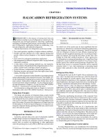
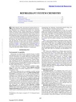
Figure 1 shows one example of a flow diagram for an HTST plate
pasteurizing system. Raw product is first introduced into a constantlevel (or balance) tank from a storage tank or receiving line by either
gravity or a pump. A uniform level is maintained in this tank by a
float-operated valve or similar device. A booster pump is often used
to direct flow through the regeneration section. The product may be
clarified and/or homogenized or directly pumped to the heating section by a timing pump. From the heating section, the product continues through a holding tube to the flow diversion valve. If the product
is at or above the preset temperature, it passes back through the opposite sides of the plates in the regeneration section and then through the
final cooling section. The flow diversion valve is set at 72°C or above;
if the product is below this minimum temperature, it is diverted back
into the balance tank for repasteurization. Heat exchange in the regeneration section causes cold raw milk to be heated by hot pasteurized
milk going downstream from the heater section and flow diversion
valve. According to the PMO, the pasteurized milk pressure must be
maintained at least 6.9 kPa above the raw. The flow rate and temperature change are about the same for both products.
Fig. 1 Flow Diagram of Plate HTST Pasteurizer
with Vacuum Chamber
Fig. 1 Flow Diagram of Plate HTST Pasteurizer
with Vacuum Chamber
33.3
Most HTST heat exchangers achieve 80 to 90% regeneration.
The cost of additional equipment to obtain more than 90% regeneration should be compared with savings in the increased regeneration to determine feasibility. The percentage of regeneration may
be calculated as follows for equal mass flow rates on either side of
the regenerator:
59C (regeneration) – 4C (raw product)
55- = 81%
--------------------------------------------------------------------------------------------------------- = -----72C (pasteurization) – 4C (raw product)
68
The temperature of a product going into the cooling section can
be calculated if the percent regeneration is known and the raw product and pasteurizing temperatures are determined. If they are 80%,
7°C, and 72°C, respectively,
(72 – 7) 0.80 = 52 K
72 – 52 = 20°C
The product should be cooled to at least 4.4°C, preferably lower,
to compensate for the heat gain while in the sanitary pipelines and
during the packaging process (including filling, sealing, casing, and
transfer into cold storage). Average temperature increases of milk
between discharge from the HTST unit’s cooling section and arrival
at the cold storage in various containers are as follows: glass bottles,
4.4 K; preformed paperboard cartons, 3.3 K; formed paperboard,
2.8 K; and semirigid plastic, 2.2 K.
Some plate pasteurizing systems are equipped with a cooling
section using propylene glycol solution to cool the milk or milk
product to temperatures lower than are practical by circulating only
chilled water. This requires an additional section in the plate heat
exchanger, a glycol chiller, a pump for circulating the glycol solution, and a product-temperature-actuated control to regulate the
flow of glycol solution and prevent product freezing.
Some plants use propylene glycol exclusively for cooling, thus
avoiding the use of chilled water and the requirement for two separate cooling sections. Milk is usually cooled with propylene glycol
to approximately 1°C, then packaged. The lower temperature allows
the milk to absorb heat from the containers and still maintain a low
enough temperature for excellent shelf life. Milk should not be
cooled to less than 0.8°C because of the tendency toward increased
foaming in this range. Propylene glycol is usually chilled to approximately –2 to –1°C for circulation through the milk-cooling section.
Product flow rate through the pasteurizer may be more or less
than the filling rate of the packaging equipment. Pasteurized product storage tanks are generally used to hold the product until it is
packaged.
The number of plates in the pasteurizing unit is determined by
the volume of product needed per unit of time, desired percentage of
regeneration, and temperature differentials between the product and
heating and cooling media. The heating section usually has ample
surface so that the temperature of hot water entering the section is no
more than 1 to 3 K higher than the pasteurizing, or outlet, temperature of the product. This temperature difference is often called the
approach of the heat exchanger section.
On larger units, steam may be used for the heater section instead
of hot water. The cooling section is usually sized so that the temperature of pasteurized product leaving the section is about 2 to 3 K
higher than the entering temperature of chilled water or propylene
glycol.
The holding tube size and length are selected so that it takes at
least 15 s for product to flow from one end of the tube to the other.
An automatic, power-actuated, flow diversion valve, controlled by
a temperature recorder-controller, is located at the outlet end of
the holding tube and diverts flow back to the raw product constant-level tank as long as the product is below the minimum set
pasteurizing temperature. The product timing pump is a variablespeed, positive-displacement, rotary type that can be sealed by the
This file is licensed to Abdual Hadi Nema (). License Date: 6/1/2010
Licensed for single user. © 2010 ASHRAE, Inc.
33.4
local government milk plant inspector at a maximum speed and
volume. This ensures a product dwell time of not less than 15 s in
the holding tube.
To reduce undesirable flavors and odors in milk (usually caused
by specific types of dairy cattle feed), some plants use a vacuum
process in addition to the usual pasteurization. Milk from the flow
diversion valve passes through a direct steam injector or steam
infusion chamber and is heated with culinary steam to 82 to 93°C.
The milk is then immediately sprayed into a vacuum chamber,
where it cools by evaporation to the pasteurizing temperature and
is promptly pumped to the regeneration section of the pasteurizing
unit. The vacuum in the evaporating chamber is automatically controlled so that the same amount of moisture is removed as was
added by steam condensate. Noncondensable gases are removed
by the vacuum pump, and vapor from the vacuum chamber is condensed in a heat exchanger cooled by the plant water.
The vacuum chamber can be installed with any type of HTST
pasteurizer. In some plants, after preheating in the HTST system,
the product is further heated by direct steam infusion or injection. It
then is deaerated in the vacuum chamber. The product is pumped
from the chamber by a timing pump through final heating, holding,
flow diversion valve, and regenerative and cooling sections.
Homogenization may occur either immediately after preheating for
pasteurization or after the product passes through the flow diversion
valve. Preferred practice is to homogenize after deaeration if the
product is heated by direct steam injection and deaerated.
Where volatile weed and feed taints in the milk are mild, some
processors use only a vacuum treatment to reduce off-flavor. The
main objection to vacuum treatment alone is that, to be effective, the
vacuum must be low enough to cause some evaporation, and the
moisture so removed constitutes a loss of product. The vacuum
chamber may be installed immediately after preheating, where it
effectively deaerates the milk before heating, or immediately after
the flow diversion valve, where it is more effective in removing volatile taints.
Nearly all milk processed in the United States is homogenized to
improve stability of the milkfat emulsion, thus preventing creaming
(concentration of the buoyant milkfat at the top of containerized
milk) during normal shelf life. The homogenizer is a high-pressure
reciprocating pump with three to seven pistons, fitted with a special
homogenizing valve. Several types of homogenizing valves are
used, all of which subject fat globules in the milk stream to enough
shear to divide into several smaller globules. Homogenizing valves
may either be single or two in series.
For effective homogenization of whole milk, fat globules should
be 2 m or less in diameter. The usual temperature range is from
54 to 82°C, and the higher the temperature within this range, the
lower the pressure required for satisfactory homogenization. The
homogenizing pressure for a single-stage homogenizing valve
ranges from about 8 to 17 MPa for milk; for a two-stage valve,
from 8 to 14 MPa on the first stage plus 2 to 5 MPa on the second,
depending on the design of the valve and the product temperature
and composition. To conserve energy, use the lowest homogenizing pressure consistent with satisfactory homogenization: the
higher the pressure, the greater the power requirements.
Packaging Milk Products
Cold product from the pasteurizer cooling section flows to the
packaging machine and/or a surge tank 4 to 38 m3 or larger. These
tanks are stainless steel, well insulated, and have agitation and usually refrigeration.
Milk and related products are packaged for distribution in paperboard, plastic, or glass containers in various sizes. Fillers vary in
design. Gravity flow is used, but positive piston displacement is
used on paper machines. Filling speeds range from roughly 16 to
250 units/min, but vary with container size. Some fillers handle only
one size, whereas others may be adjusted to automatically fill and
2010 ASHRAE Handbook—Refrigeration (SI)
seal several size containers. Paperboard cartons are usually formed
on the line ahead of filling, but may be preformed before delivery to
the plant. Semirigid plastic containers may be blow-molded on the
line ahead of the filler or preformed. Plastic pouches (called bags)
arrive at the plant ready for filling and sealing. Filling dispenser
cans and bags is a semimanual operation.
The paperboard milk carton consists of a 0.41 mm thick kraft
paperboard from virgin paper with a 0.025 mm polyethylene film
laminated onto the inside and a 0.019 mm film onto the outside. Gas
or electric heaters supply heat for sealing while pressure is applied.
Blow-molded plastic milk containers are fabricated from highdensity polyethylene resin. The resin temperature for blow-forming
varies from 170 to 218°C. The molded 4 L has a mass of approximately 60 to 70 g, and the 2 L, about 45 g. Contact the blowmolding equipment manufacturer for refrigeration requirements of
a specific machine. The refrigeration demand to cool the mold head
and clutch is large enough to require consideration in planning a
plastic blow-molded operation. Blow-molding equipment may use
stand-alone direct-expansion water chillers, or combine blowmolding refrigeration with the central refrigeration system to
achieve better overall efficiency.
Packages containing the product may be placed into cases
mechanically. Stackers place cases five or six high, and conveyors
transfer stacks into the cold storage area.
Equipment Cleaning
Several automatic clean-in-place (CIP) systems are used in milk
processing plants. These may involve holding and reusing the detergent solution or the preparation of a fresh solution (single-use) each
day. Programming automatic control of each cleaning and sanitizing
step also varies. Tanks, vats, and other large equipment can be
cleaned by using spray balls and similar devices that ensure complete coverage of soiled surfaces. Tubing, HTST units, and equipment with relatively low volume may be cleaned by the full-flood
system. Solutions should have a velocity of not less than 1.5 m/s and
must be in contact with all soiled surfaces. Surfaces used for heating
milk products, such as in batch or HTST pasteurization, are more
difficult to clean than other equipment surfaces. Other surfaces difficult to clean are those in contact with products that are high in fat,
contain added solids and/or sweeteners, or are highly viscous. The
usual cleaning steps for this equipment are a warm-water rinse, hotacid-solution wash, rinse, hot-alkali-solution wash, and rinse. Time,
temperature, concentration, and velocity may need to be adjusted for
effective cleaning. Just before use, surfaces in contact with product
should be sanitized with chemical solution, hot water, or steam. During CIP, the cooling section is isolated from the supply of chilled
water or propylene glycol to minimize parasitic load on the refrigeration system.
Milk Storage and Distribution
Cases containing packaged products are conveyed into a coldstorage room or directly to delivery trucks for wholesale or retail
distribution. The temperature of the storage area should be between
0.6 and 4.4°C, and for improved keeping quality, the product temperature in the container on arrival in storage should be 4.4°C or less.
The refrigeration load for cold-storage areas includes transmission through the building envelope, product and packaging materials
temperature reduction, internally generated loads (e.g., lights, equipment motors, personnel), infiltration load from air exchange with
other spaces and the environment, and refrigeration equipmentrelated load (e.g., fan motors, defrost). See Chapter 13 for a more
detailed discussion of refrigeration load calculations.
Moisture load in these storage areas is generally high, which can
lead to high humidity or wet conditions if evaporators are not selected
properly. These applications usually require higher temperature differences between refrigerant and refrigerated-space set-point temperatures to achieve lower humidity. In addition, supply air temperatures
This file is licensed to Abdual Hadi Nema (). License Date: 6/1/2010
Licensed for single user. © 2010 ASHRAE, Inc.
Dairy Products
should be controlled to prevent product freezing. Using reheat coils
to provide humidity control is not recommended, because bacteriological growth on these surfaces could be rapid. Evaporators for these
applications should have automatic coil defrost to remove the rapidly
forming frost as required. Defrost cycles add to the refrigeration load
and should be considered in the design.
A proprietary system used in some plants sprays coils continuously with an aqueous glycol solution to prevent frost from forming
on the coil. These fan-coil units eliminate defrosting, can control
humidity to an acceptable level with less danger of product freezing,
and reduce bacteriological contamination. The glycol absorbs the
water, which is continuously reconcentrated in a separate apparatus
with the addition of heat to evaporate the water absorbed at the coil.
A separate load calculation and analysis is required for these systems.
The floor space required for cold storage depends on product volume, height of stacked cases, packaging type (glass requires more
space than paperboard), handling (mechanized or manual), and
number of processing days per week. A 5 day processing week
requires a capacity for holding product supply for 2 days. A very
general estimate is that 490 kg of milk product in paperboard cartons can be stored per square metre of area. Approximately onethird more area should be allowed for aisles. Some automated,
racked storages are used for milk products, and can be more economical than manually operated storages.
Milk product may be transferred by conveyor from storage room
to dock for loading onto delivery trucks. In-floor drag-chain conveyors are commonly used, especially for retail trucks. Refrigeration losses are reduced if the load-out doorway has an air seal to
contact the doorway frame of the truck as it is backed to the dock.
Distribution trucks need refrigeration to protect quality and
extend storage life of milk products. Refrigeration capacity must be
sufficient to maintain Grade A products at 7.2°C or less. Many plants
use insulated truck trailer bodies with integral refrigerating systems
powered by an engine or that can be plugged into a remote electric
power source when it is parked. In some facilities, cold plates in the
truck body are connected to a coolant source in the parking space.
These refrigerated trucks can also be loaded when convenient and
held over at the connecting station until the next morning.
Half-and-Half and Cream
Half-and-half is standardized at 10.5 to 12% milkfat and, in most
areas of the United States, to about the same percent nonfat milk solids. Coffee cream should be standardized at 18 to 20% milkfat. Both
are pasteurized, homogenized, cooled, and packaged similarly to
milk. Milkfat content of whipping cream is adjusted to 30 to 35%.
Take care during processing to preserve the whipping properties;
this includes the omission of the homogenization step.
Buttermilk, Sour Cream, and Yogurt
Retail buttermilk is not from the butter churn but is instead a
cultured product. To reduce microorganisms to a low level and
improve the body of the resulting buttermilk, skim milk is pasteurized at 82°C or higher for 0.5 to 1 h and cooled to 21 to 22°C. One
percent of a lactic acid culture (starter) specifically for buttermilk
is added and the mixture incubated until firmly coagulated by the
correct lactic acid production (pH 4.5). The product is cooled to
4.4°C or less with gentle agitation to inhibit serum separation after
packaging and distribution. Salt and/or milkfat (0.5 to 1.0%) in the
form of cream or small fat granules may be added. Packaging
equipment and containers are the same as for milk. Pasteurizing,
setting, incubating, and cooling are usually accomplished in the
same vat. Rapid cooling is necessary, so chilled water is used. If a
2 m3 vat is used, as much as 90 to 110 kW of refrigeration may be
needed. Some plants have been able to cool buttermilk with a plate
heat exchanger without causing a serum separation problem
(wheying off).
33.5
Cultured half-and-half and cultured sour cream are also manufactured this way. Rennet may be added at a rate of 1.3 mL (diluted
in water) per 100 L cream. Take care to use an active lactic culture
and to prevent postpasteurization contamination by bacteriophage,
bacteria, yeast, or molds. An alternative method is to package the
inoculated cream, incubate it, and then cool by placing packages in
a refrigerated room.
For yogurt, skim milk may be used, or milkfat standardized to
1 to 5%, and a 0.1 to 0.2% stabilizer may be added. Either vat pasteurization at 66 to 93°C for 0.5 to 1 h or HTST at 85 to 140°C for
15 to 30 s can be used. For optimum body, milk homogenization is
at 54 to 66°C and 3.5 to 14 MPa. After cooling to between 38 to
43°C, the product is inoculated with a yogurt culture. Incubation for
1.5 to 2.0 h is necessary; the product is then cooled to about 32°C,
packaged, incubated 2 to 3 h (acidity 0.80 to 0.85%), and chilled to
4.4°C or below in the package. Varying yogurt cultures and manufacturing procedures should be selected on the basis of consumer
preferences. Numerous flavorings are used (fruit is quite common),
and sugar is usually added. The flavoring material may be added at
the same time as the culture, after incubation, or ahead of packaging. In some dairy plants, a fruit (or sauce) is placed into the package
before filling with yogurt.
Refrigeration
The refrigerant of choice for production plants is usually
ammonia (R-717). Some small plants may use halocarbon refrigerants; in large plants, halocarbons may be used with a centralized
ammonia refrigeration system for special, small applications. The
halocarbon refrigerant of choice is currently R-22; however, the
Montreal Protocol outlines a phaseout schedule for the use of R-22
and other hydrochlorofluorocarbon (HCFC) refrigerants. Currently, no consensus alternative for R-22 has been identified. Two
HFC blends, R-507 and R-404a, are currently favored for refrigeration applications.
Product plants use single-stage compression, and new applications are equipped with rotary screw compressors with microprocessors and automatic control. Older plants may be equipped with
reciprocating compressors, but added capacity is generally with
rotary screw compressors.
Most refrigerant condensing is accomplished with evaporative
condensers. Freeze protection is required in cold climates, and
materials of construction are an important consideration in subtropical climates. Water treatment is required.
Evaporators or cooling units for milk storage areas use either
direct ammonia (direct-expansion, flooded or liquid overfeed),
chilled water, or propylene glycol. In choosing new systems, evaluation should involve capital requirements, operating costs, ammonia
charges, and plant safety.
Direct use of ammonia has the potential for the lowest operating
cost because the refrigeration system does not have the increased
losses associated with exchanging heat with a secondary cooling
medium (chilled water or propylene glycol). However, direct use of
ammonia requires larger system charges and more ammonia in production areas.
To limit ammonia charges in production areas, many plants use
a secondary cooling system that circulates chilled water or propylene glycol where needed. If chilled water is used, it must be supplied at 0.5 to 1°C to cool milk products below 4.4°C. Chilled
water is often used in combination with falling-film water chillers
and ice-building chillers to cool water so close to its freezing point.
Ice-building and falling-film chillers should be compared for each
application, considering both initial capital and operating costs.
Sizing ice builders to build ice during periods when chilled water
is not required allows installation of a refrigeration system with
considerably less capacity than is required for the peak cooling
load. When chilled water is required, melting ice adds cooling
capacity to that supplied by the refrigeration system. Additional
This file is licensed to Abdual Hadi Nema (). License Date: 6/1/2010
Licensed for single user. © 2010 ASHRAE, Inc.
33.6
2010 ASHRAE Handbook—Refrigeration (SI)
information on ice thermal storage is found in Chapter 34 of the
2007 ASHRAE Handbook—HVAC Applications. The advantage of
this system is a lower ammonia charge compared to the direct use
of ammonia.
Other plants use propylene glycol at –2 to –1°C for process cooling requirements. This system cools propylene glycol in a weldedplate or shell-and-tube heat exchanger. The ammonia feed system is
either gravity-flooded or liquid-overfeed. Advantages to this system
are a reduced ammonia charge compared to direct use of ammonia
(especially with a plate heat exchanger) and a lower cooling fluid
temperature to achieve lower milk product temperatures. This system may have a higher operating cost, because there is no stored
refrigeration, and possibly higher pumping requirements compared
to chilled water. Commercially available propylene glycol packages
for closed cooling systems include biological growth and corrosion
inhibitors. The concentration of propylene glycol necessary in the
system should be determined by consulting the glycol manufacturer
to ensure adequate freeze protection as well as protection against
biological growth and corrosion.
In addition, there are combination systems in which chilled water
is used for most of the process requirements and a separate, smaller
propylene glycol system is used in final cooling sections to provide
lower milk product temperatures.
Other plant refrigeration loads, such as air conditioning of process areas, may be met with the central ammonia refrigeration system. The choice between chilled water and propylene glycol may
also depend on the plant winter climate conditions and location of
piping serving the loads.
Most new or expanded plants rely on automated operation and
computer controls for operating and monitoring the refrigeration
systems. There also is a trend to use welded-plate heat exchangers
for water and propylene glycol cooling in milk product plants and to
reduce or eliminate direct ammonia refrigeration in plant process
areas. This approach may add somewhat to the capital and operating
costs, but it can substantially reduce the ammonia charge in the system and confines ammonia to the refrigeration machine room area.
BUTTER MANUFACTURE
Much of the butter production is in combination butter-powder
plants. These plants get the excess milk production after current
market needs are met for milk products, frozen dairy desserts, and,
to some extent, cheeses. Consequently, seasonal variation in the volume of butter manufactured is large; spring is the period of highest
volume, fall the lowest.
Separation and Pasteurization
After separation, cream with 30 to 40% fat content is either
pumped to the pasteurizer or cooled to 7°C and held for later pasteurization. Cream from cold milk separation does not need to be
recooled except for extended storage. Cream is received, weighed,
sampled, and, in some plants, graded according to flavor and
acidity. It is pumped to a refrigerated storage vat and cooled to
7.2°C if held for a short period or overnight. Cream with developed
acidity is warmed to 27 to 32°C, and neutralized to 0.12 to 0.15%
titratable acidity just before pasteurization. If acidity is above
0.40%, it is neutralized with a soda-type compound in aqueous
solution to about 0.30% and then to the final acidity with aqueous
lime solution. Sodium neutralizers include NaHCO3, Na2CO3, and
NaOH. Limes are Ca(OH)2, MgO, and CaO.
Batch pasteurization is usually at 68 to 79°C for 0.5 h, depending
on intended storage temperature and time. HTST continuous pasteurization is at 85 to 121°C for at least 15 s. HTST systems may be
plate or tubular. After pasteurization, the cream is immediately
cooled. The temperature range is 4 to 13°C, depending on the time
that the cream will be held before churning, whether it is ripened,
season (higher in winter because of fat composition), and churning
method. Ripening consists of adding a flavor-producing lactic
starter to tempered cream and holding until acidity has developed to
0.25 to 0.30%. The cream is cooled to prevent further acid development and warmed to the churning temperature just before churning.
First, tap water is used to reduce the temperature to between 25
to 35°C. Refrigerated water or brine is then used to reduce the temperature to the desired level. The cream may be cooled by passing
the cooling medium through a revolving coil in the vat or through
the vat jacket, or by using a plate or tubular cooler. Ripening cream
is not common in the United States, but is customary in some European countries such as Denmark.
If the temperature of 500 kg of cream is to be reduced by refrigerated water from 40 to 4°C, and the specific heat is 3.559 kJ/(kg·K),
the heat to be removed is
500(40 – 4)3.559 = 64 062 kJ
This heat can be removed by 64 062/335 = 191 kg of ice at 0°C
plus 10% for mechanical loss.
The temperature of refrigerated water commonly used for cooling cream is 0.6 to 1.1°C. The ice-builder system is efficient for this
purpose. Brine or glycol is not currently used. About 1000 L of
cream can be cooled from 37.7 to 4.4°C in a vat using refrigerated
water in an hour.
After a vat of cream has cooled to the desired temperature, the
temperature increases during the following 3 h because heat is liberated when fat changes from liquid to a crystal form. It may
increase several degrees, depending on the rapidity with which the
cream was cooled, the temperature to which it was cooled, the richness of the cream, and the properties of the fat.
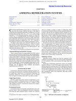
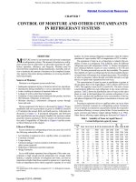
Rishoi (1951) presented data in Figure 2 that show the thermal
behavior of cream heated to 75°C followed by rapid cooling to 30°C
and to 10.4°C, as compared with cream heated to 50°C and cooled
rapidly to 31.4°C and to 12°C. The curves indicate that when cream
is cooled to a temperature at which the fat remains liquid, the cooling rate is normal, but when the cream is cooled to a temperature at
which some fractions of the fat have crystallized, a spontaneous
temperature rise takes place after cooling.
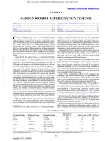
Rishoi also determined the amount of heat liberated by the part of
the milkfat that crystallizes in the temperature range of 29 to 0.6°C.
The results are shown in Figure 3 and Table 2.
Table 2 shows that, at a temperature below 10°C, about one-half
of the liberated heat evolved in less than 15 s. The heat liberated
during fat crystallization constitutes a considerable portion of the
refrigeration load required to cool fat-rich cream. Rishoi states,
If we assume an operation of cooling cream containing 40% fat from
about 65 to 4°C, heat of crystallization evolved represents about 14%
of the total heat to be removed. In plastic cream containing 80% fat
it represents about 30% and in pure milkfat oil about 40%.
Churning
To maintain the yellow color of butter from cream that came
from cows on green pasture in spring and early summer, yellow coloring can be added to the cream to match the color obtained naturally during other periods of the year. After cooling, pasteurized
cream should be held a minimum of 2 h and preferably overnight. It
is tempered to the desired batch churning temperature, which varies
with the season and feed of the cows but ranges from 7°C in early
summer to 13°C in winter, to maintain a churning time 0.5 to 0.75 h.
Lower churning time results in soft butter that is more difficult (or
impossible) to work into a uniform composition.
Most butter is churned by continuous churns, but some batch
units remain in use, especially in smaller butter factories. Batch
churns are usually made of stainless steel, although a few aluminum
ones are still in use. They are cylinder, cube, cone, or double cone in
shape. The inside surface of metal churns is sandblasted during fabrication to reduce or prevent butter from sticking to the surface.
Metal churns may have accessories to draw a partial vacuum or
This file is licensed to Abdual Hadi Nema (). License Date: 6/1/2010
Dairy Products
33.7
Licensed for single user. © 2010 ASHRAE, Inc.
Fig. 2 Thermal Behavior of Cream Heated to 75°C Followed
by Rapid Cooling to 30°C and to 10.4°C; Comparison with
Cream Heated to 50°C, then Rapid Cooling to 31.4°C and to
12°C
Fig. 2 Thermal Behavior of Cream Heated to 75°C Followed by
Rapid Cooling to 30°C and to 10.4°C; Comparison with Cream
Heated to 50°C, then Rapid Cooling to 31.4°C and to 12°C
Table 2 Heat Liberated from Fat in Cream Cooled Rapidly
from about 30°C to Various Temperatures
Calculated temperature
for zero time, °C:
0.8
4.2
11.7
14.4 17.4
26.9 29.8*
First observed
temperature:
2.3
6.5
12.5
14.8 17.7
26.9
29.8
Final equilibrium
temperature:
4.1
7.8
14.4
15.9 18.5
28.1
29.8
0
0.8
4.9
6.3
6.7
10.0
11.4
11.6
11.6
0
0
0
0
0
0
Lapsed time, min
0.25
15
30
60
120
180
240
300
360
Heat Liberated, kJ/kg
42.6
54.9
59.3
70.7
75.4
76.5
79.1
78.2
78.2
38.8
46.5
55.6
64.0
68.2
70.2
71.9
74.0
75.6
18.0
29.8
41.9
49.8
58.2
61.9
63.3
64.9
63.3
6.7
16.7
28.4
32.6
34.2
37.2
40.7
42.8
43.7
5.3
12.1
20.9
23.7
24.7
24.7
24.7
Percent heat liberated at zero time compared with that at equilibrium: 54.5, 51.3, 27.7,
20.7, 21.7.
Percent total heat liberated compared with that liberated at about 0°C: 100.0, 95.7,
82.0, 55.0, 31.0, 12.5, 0.
Iodine values of three samples of butter produced while these tests were in progress
were 28.00, 28.55, and 28.24.
*Cooled in an ice-water bath.
introduce an inert gas (e.g., nitrogen) under pressure. Working
under a partial vacuum reduces air in the butter. Churns have two or
more speeds, with the faster rate for churning. The higher speed
should provide maximum agitation of the cream, usually between
0.25 to 0.5 rev/s.
When churning, temperature is adjusted and the churn is filled
to 40 to 48% of capacity. The churn is revolved until the granules
Fig. 3 Heat Liberated from Fat in Cream Cooled Rapidly
from Approximately 86°F to Various Temperatures
Fig. 3 Heat Liberated from Fat in Cream Cooled Rapidly from
Approximately 30°C to Various Temperatures
(Rishoi 1951)
break out and attain a diameter of 5 mm or slightly larger. The buttermilk, which should have no more than 1% milkfat, is drained.
The butter may or may not be washed. The purpose of washing is
to remove buttermilk and temper the butter granules if they are too
soft for adequate working. Wash water temperature is adjusted to
0 to 6 K below churning temperature. The preferred procedure is to
spray wash water over granules until it appears clear from the
churn drain vent. The vent is then closed, and water is added to the
churn until the volume of butter and water is approximately equal
to the former amount of the cream. The churn revolves slowly 12
to 15 times and drained or held for an additional 5 to 15 min for
tempering so granules will work into a mass of butter without
becoming greasy.
The butter is worked at a slow speed until free moisture is no longer extruded. Free water is drained, and the butter is analyzed for
moisture content. The amount of water needed to obtain the desired
content (usually 16.0 to 18.0%) is calculated and added. Salt may be
added to the butter. The salt content is standardized between 1.0 and
2.5% according to customer demand.
Dry salt may be added either to a trench formed in the butter or
spread over the top of the butter. It also may be added in moistened
form, using the water required for standardizing the composition to
not less than 80.0% fat. Working continues until the granules are
completely compacted and the salt and moisture droplets are uniformly incorporated. Moisture droplets should become invisible to
normal vision with adequate working. Most churns have ribs or
vanes, which tumble and fold the butter as the churn revolves. The
butter passes between the narrow slit of shelves attached to the shell
and the roll. A leaky butter is inadequately worked, possibly leading
to economic losses because of mass reduction and shorter keeping
quality. The average composition of U.S. butter on the market has
these ranges:
Fat
Salt
80.0 to 81.2%
1.0 to 2.5%
Moisture
Curd, etc.
16.0 to 18.0%
0.5 to 1.5%
This file is licensed to Abdual Hadi Nema (). License Date: 6/1/2010
33.8
Cultured skim milk is added to unsalted butter as part of the
moisture and thoroughly mixed in during working. On rare occasions, cultured skim milk may be used to increase acid flavor and the
diacetyl content associated with butter flavor.
Butter may be removed manually from small churns, but it is
usually emptied mechanically. One method is to dump butter from
the churn directly into a stainless steel boat on casters or a tray that
has been pushed under the churn with the door removed. Butter in
boats may be augered to the hopper for printing (forming the butter
into retail sizes) or pumping into cartons 27 to 30 kg in size. The
bulk cartons are held cold before printing or shipment. Butter may
be stored in the boats or trays and tempered until printing. A hydraulic lift may be used for hoisting the trays and dumping the butter into
the hopper. Cone-shaped churns with a special pump can be emptied
by pumping butter from churn to hopper.
2010 ASHRAE Handbook—Refrigeration (SI)
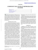
Fig. 4 Flow Diagram of Continuous Butter Manufacture
Fig. 4 Flow Diagram of Continuous Butter Manufacture
Table 3
Continuous Churning
Licensed for single user. © 2010 ASHRAE, Inc.
The basic steps in two of the continuous buttermaking processes
developed in the United States are as follows:
1. Fat emulsion in the cream is destabilized and the serum separated
from the milkfat.
2. The butter mix is prepared by thoroughly blending the correct
amount of milkfat, water, salt, and cultured skim milk (if necessary).
3. This mixture is worked and chilled at the same time.
4. Butter is extruded at 3 to 10°C with a smooth body and texture.
Some European continuous churns consist of a single machine
that directly converts cream to butter granules, drains off the buttermilk, and washes and works the butter, incorporating the salt in
continuous flow. Each brand of continuous churn may vary in
equipment design and specific operation details for obtaining the
optimum composition and quality control of the finished product.
Figure 4 shows a flow diagram of a continuous churn.
In one such system, milk is heated to 43.3°C and separated to
cream with 35 to 50% fat and skim milk. The cream is pasteurized at
95°C for 16 s, cooled to a churning temperature of 8 to 14°C, and
held for 6 h. It then enters the balance tank and is pumped to the
churning cylinder, where it is converted to granules and serum in less
than 2 s by vigorous agitation. Buttermilk is drained off and the granules are sprayed with tempered wash water while being agitated.
Next, salt, in the form of 50% brine prepared from microcrystalline sodium chloride, is fed into the product cylinder by a proportioning pump. If needed, yellow coloring may be added to the brine.
High-speed agitators work the salt and moisture into the butter in the
texturizer section and then extrude it to the hopper for packaging
into bulk cartons or retail packages. The cylinders on some designs
have a cooling system to maintain the desired temperature of the
butter from churning to extrusion. The butterfat content is adjusted
by fat test of the cream, churning temperature of the cream, and flow
rate of product.
Continuous churns are designed for CIP. The system may be
automated or the cream tank may be used to prepare the detergent
solution before circulation through the churn after the initial rinsing.
Packaging Butter
Printing is the process of forming (or cutting) butter into retail
sizes. Each print is then wrapped with parchment or parchmentcoated foil. The wrapped prints may be inserted in paperboard
cartons or overwrapped in cellophane, glassine, and so forth, and
heat-sealed. For institutional uses, butter may be extruded into
slabs. These are cut into patties, embossed, and each slab of patties
wrapped in parchment paper. Most common numbers of patties are
105 to 158 per kg.
Butter keeps better if stored in bulk. If the butter is intended to
be stored for several months, the temperature should not be above
–18°C, and preferably below –30°C. For short periods, 0 to 4°C is
Whey
Skim milk
Whole milk
15% cream
20% cream
30% cream
45% cream
60% cream
Butter
Milkfat
Specific Heats of Milk and Milk Derivatives,
kJ/(kg·K)
0°C
15°C
40°C
60°C
4.095
3.936
3.852
3.140
3.027
2.818
2.537
2.345
(2.114)*
(1.863)*
4.086
3.948
3.927
3.864
3.936
4.116
4.254
4.409
(2.207)*
(1.955)*
4.078
3.986
3.984
3.764
3.684
3.567
3.295
3.019
2.328
2.093
4.070
4.932
3.844
3.768
3.710
3.601
3.320
3.086
2.438
2.219
*For butter and milkfat, values in parentheses were obtained by extrapolation, assuming that the specific heat is about the same in the solid and liquid states.
satisfactory for bulk or printed butter. Butter should be well protected to prevent absorption of off-odors during storage and weight
loss from evaporation, and to minimize surface oxidation of fat.
The specific heat of butter and other dairy products at temperatures varying from 0 to 60°C is given in Table 3. The butter temperature when removed from the churn ranges from 13 to 16°C.
Assuming a temperature of 15°C of packed butter, the heat that must
be removed from 500 kg to reduce the temperature to 0°C is
500(15 – 0)2.18/1000 = 16.4 MJ
It is assumed that the average specific heat at the given range of
temperatures is 2.18 kJ/(kg·K). Heat to be removed from butter containers and packaging material should be added.
Deterioration of Butter in Storage
Undesirable flavor in butter may develop during storage because
of (1) growth of microorganisms (proteolytic organisms causing
putrid and bitter off-flavors); (2) absorption of odors from the atmosphere; (3) fat oxidation; (4) catalytic action by metallic salts;
(5) activity of enzymes, principally from microorganisms; and
(6) low pH (high acid) of salted butter.
Normally, microorganisms do not grow below 0°C; if salttolerant bacteria are present, their growth will be slow below 0°C.
Microorganisms do not grow at –18°C or below, but some may survive in butter held at this temperature. It is important to store butter
in a room free of atmospheric odors. Butter readily absorbs odors
from the atmosphere or from odoriferous materials with which it
comes into contact.
Oxidation causes a stale, tallowy flavor. Chemical changes take
place slowly in butter held in cold storage, but are hastened by the
presence of metals or metallic oxides.
With almost 100% replacement of tinned copper equipment with
stainless steel equipment, a tallowy flavor is not as common as in the
past. Factors that favor oxidation are light, high acid, high pH, and
metal.
This file is licensed to Abdual Hadi Nema (). License Date: 6/1/2010
Dairy Products
Enzymes present in raw cream are inactivated by current pasteurization temperatures and holding times. The only enzymes that may
cause butter deterioration are those produced by microorganisms that
gain entrance to the pasteurized cream and butter or survive pasteurization. The chemical changes caused by enzymes present in butter
are retarded by lowering the storage temperature.
A fishy flavor may develop in salted butter during cold storage.
Development of the defect is favored by high acidity (low pH) of the
cream at the time of churning and by metallic salts. With the use of
stainless steel equipment and proper control of the butter’s pH, this
defect now occurs very rarely. For salted butter to be stored for several months, even at –23°C, it is advisable to use good-quality
cream; avoid exposing the milk or cream to strong light, copper, or
iron; and adjust any acidity developed in the cream so that the butter
serum has a pH of 6.8 to 7.0.
Total Refrigeration Load
Licensed for single user. © 2010 ASHRAE, Inc.
Some dairy plants that manufacture butter also process and manufacture other products such as ice cream, fluid milk, and cottage
cheese. A single central refrigeration system is used to provide
refrigeration to all of these loads. The method of determining the
refrigeration load is illustrated by the following example.
Example 1. Determine the product refrigeration load for a plant manufacturing butter from 6000 kg of 30% cream per day in three churnings.
Solution: Assume that refrigeration is accomplished with chilled water
from an ice builder. See Figure 5 for a workflow diagram.
The cream is cooled in steps A and B. The butter is then cooled
through steps C, D, and E. Refrigerated water is normally used as a
cooling medium in steps A, B, and C. The ice builder system is used to
produce 2°C water, and the load should be expressed in kilograms of
ice that must be melted to handle steps A, B, and C. This load is added
33.9
to the refrigerated water load from the various other products such as
milk, cottage cheese, and so forth, in sizing the ice builder.
A. If cream is separated in the plant rather than on the farm, it must
be cooled from 32°C separating temperature to 4°C for holding until it
is processed.
6000 32 – 4 3.56
------------------------------------------- = 1790 kgice/day
335
B. After pasteurization, the temperature of the cream is reduced to
approximately 38°C with city water, then down to 4°C with refrigeration.
6000 38 – 4 3.56
------------------------------------------- =2170 kgice/day
335
C. After churning, the 15°C butter wash water (city water) is usually cooled to 7°C, then used to wash the butter granules. A mass of
water equal to the mass of cream churned may be used.
6000 15 – 7 4.187
---------------------------------------------- = 600 kgice/day
335
Total ice load 4560 kgice /day
Plus 10% mechanical loss 460 kgice /day
Total ice required 5020 kgice /day
D. Approximately 2250 kg of butter is obtained.6000 kg cream
30% fat = 1800 kg of fat. If butter contains approximately 80% fat,
1800 kg divided by 80% equals approximately 2250 kg of butter. The
butter temperature going into the refrigerated storage room is usually
about 17°C and must be cooled to 4°C in the following 16 h. (For longterm storage, butter is held at –23 to –17°C.) The average specific heat
for butter over this range is 2.30 kJ/(kg·K).
2250(17 – 4)2.30 = 67.3 MJ
135 kg (metal container) (24 – 4)0.50 = 1.4 MJ
Total/24 h
Fig. 5 Butter Flow Diagram
68.7 MJ
E. After 24 h or longer, the butter is removed from the cooler to be
cut and wrapped in 450 g or smaller units. During this process, the butter temperature rises to approximately 13°C, which constitutes another
product load in the cooler when it goes back for storage.
2250(13 – 4)2.30 = 46.6 MJ
90 kg (paper container) (24 – 4)1.38 = 2.5 MJ
Total/24 h
49.1 MJ
Total of Steps D and E, Product Load in Cooler:
1000 68.7 + 49.1
-------------------------------------------- = 2.05 kW
16 h 3600
Whipped Butter
Fig. 5 Butter Flow Diagram
To whip butter by the batch method, the butter is tempered to
17 to 21°C, depending on factors such as the season and type of
whipper. The butter is cut into slabs for placing into the whipping
bowl. The whipping mechanism is activated, and air is incorporated
until the desired overrun (volume increase) is obtained, usually
between 50 and 100%. Whipped butter is packaged mechanically or
manually into semirigid plastic containers.
With one continuous system, butter directly from cooler storage is
cut into pieces and augered until soft. However, it can be tempered
and the augering step omitted. The butter is then pumped into a cylindrical continuous whipper that uses the same principles as those for
incorporating air in ice cream. Air or nitrogen is incorporated until
the desired overrun is obtained. Another continuous method (used
less commercially) is to melt butter or standardize butter oil to the
composition of butter with moisture and salt. The fluid product is
pumped through a chiller/whipper. Metered air or nitrogen provides
overrun control. Soft whipped butter is pumped to the hopper of the
filler and packaged in rigid or semirigid containers, such as plastic.
It is chilled and held in storage at 0 to 4.4°C.
This file is licensed to Abdual Hadi Nema (). License Date: 6/1/2010
33.10
2010 ASHRAE Handbook—Refrigeration (SI)
Licensed for single user. © 2010 ASHRAE, Inc.
CHEESE MANUFACTURE
Approximately 800 cheeses have been named, but there are only
18 distinctly different types. A few of the more popular types in the
United States are cheddar, cottage, roquefort or blue, cream, ricotta,
mozzarella, Swiss, edam, and provolone. Details of manufacture
such as setting (starter organisms, enzyme, milk or milk product,
temperature, and time), cutting, heating (cooking), stirring, draining, pressing, salting, and curing (including temperature and humidity control) are varied to produce a characteristic variety and its
optimum quality.
Production of cheddar cheese in the United States currently
exceeds the other cured varieties; however, mozzarella production is
a close second and is gaining fast. For uncured cheese varieties, cottage cheese production is much greater than that of the others.
Another trend in the cheese industry is large factories. These plants
may have sufficient curing facilities for the total production. If not,
the cheese is shipped to central curing plants.
The physical shape of cured cheese varies considerably. Barrel
cheese is common; it is cured in a metal barrel or similar impervious
container in units of approximately 225 kg. Cheese may also be
cured in rectangular metal containers holding 900 kg.
The microbiological flora of cured cheese are important in develing flavor and body. Heating the milk for cheese is the general practice. The milk may be pasteurized at the minimum HTST conditions
or be given a subpasteurization treatment that results in a positive
phosphatase test, which checks for inactivated enzymes indicating
the presence of raw milk. Subpasteurization is possible with goodquality milk (low level of spoilage microorganisms and pathogens).
Such milk treatments give the cheese some characteristics of rawmilk cheese in curing, such as production of higher flavors, in a
shorter time. Pasteurization to produce phosphatase-negative milk is
used in making soft, unripened varieties of cheese and some of the
more perishable of the ripened types such as camembert, limburger,
and munster.
The standards and definitions of the Food and Drug Administration (FDA) and of most state regulatory agencies require that
cheese that is not pasteurized must be cured for not less than 60
days at not less than 1.7°C. Raw-milk cheese contains not only
lactic-acid-producing organisms such as Lactococcus lactis,
which are added to the milk during cheesemaking, but also the heterogeneous mixture of microorganisms present in the raw milk,
many of which may produce gas and off-flavors in the cheese. Pasteurization gives some control over the bacterial flora of the
cheese.
Freshly manufactured cured cheese is rubbery in texture and has
little flavor; perhaps the more characteristic flavor is slightly acid.
The presence of definite flavor(s) in freshly made cheese indicates
poor quality, probably resulting from off-flavored milk. On curing
under proper conditions, however, the body of the cheese breaks
down, and the nut-like, full-bodied flavor characteristic of aged
cheese develops. These changes are accompanied by certain chemical and physical changes during curing. The calcium paracaseinate
of cheese gradually changes into proteoses, amino acids, and
ammonia. These changes are a part of ripening and may be controlled by time and temperature of storage. As cheese cures, varying
degrees of lipolytic activity also occur. In the case of blue or roquefort cheese, this partial fat breakdown contributes substantially to
the characteristic flavor.
During curing, microbiological development produces changes
according to the species and strains present. It is possible to predict
from the microorganism data some of the usual defects in cheddar.
In some cheeses (e.g., Swiss), gas production accompanies the
desirable flavor development.
Cheese quality is evaluated on the basis of a scorecard. Flavor
and odor, body and texture, and color and finish are principal factors. They are influenced by milk quality, skill of manufacturing
(including starter preparation), and control effectiveness of maintaining optimum curing conditions.
Cheddar Cheese
Manufacture. Raw or pasteurized whole milk is tempered to 30
to 31°C and pumped to a cheese vat, which typically holds approximately 18 Mg of milk. It is set by adding 0.75 to 1.25% active cheese
starter and possibly annatto yellow color, depending on market
demand. After 15 to 30 min, when the milk has reached the proper
acidity (0.05 to 0.1%), 218 mL of single-strength rennet per 1000 kg
milk is diluted in water 1:40 and slowly added with agitation of milk
in the vat. After a quiescent period of 25 to 30 min, the curd should
have developed proper firmness. The curd is cut into 6 to 10 mm
cubes. After 15 to 30 min of gentle agitation, cooking begins by heating water in the vat jacket using steam or hot water for 30 to 40 min.
The curd and whey should increase 1 K per 5 min, and a temperature
of 38 to 39°C is maintained for approximately 45 min.
In batch systems, the whey is drained and curd is trenched along
both sides of the vat, allowing a narrow area free of curd the length
of the midsection of the vat. Slabs about 250 mm long are cut and
inverted at 15 min periods during the cheddaring process (matting
together of curd pieces). When acidity of the small whey drainage is
at a pH of 5.3 to 5.2, the slabs are milled (cut into small pieces) and
returned to the vat for salting and stirring, or the curd goes to a
machine that automatically adds salt and uniformly incorporates it
into the curd. Weighed curd goes into hoops, which are placed into
a press, and 140 kPa is applied. After 0.5 to 1 h, the hoops are taken
out of the press, the bandage adjusted to remove wrinkles, and then
the cheese is pressed overnight at 170 to 210 kPa or higher. Cheese
may be subjected to a vacuum treatment to improve body by reducing or eliminating air pockets. After the surface is dried, the cheese
is coated by dipping into melted paraffin or wrapped with one of
several plastic films, or oil with a plastic film, and sealed. Yield is
about 10 kg per 100 kg of milk.
Faster and more mechanized methods of making cheddar cheese
have evolved. The stirred curd method (which omits the cheddaring
step) is being used by more cheesemakers. Deep circular or oblong
cheese vats with special, reversible agitators and means for cutting
the curd are becoming popular. Curd is pumped from these vats to
draining and matting tables with sloped bottoms and low sides, then
milled, salted, and hooped. In one method, curd (except for Odenburg cheddar) is carried and drained by a draining/matting conveyor
with a porous plastic belt to a second belt for cheddaring and transport to the mill. The milled curd is then carried to a finishing table
or conveyor, where it is salted, stirred, and moved out for hooping or
to block formers.
Another system, imported from Australia, is used in a number of
cheddar cheese factories. This system requires a short method of
setting. After the curd is cut and cooked, it is transferred to a series
of perforated stainless steel troughs traveling on a conveyor for
draining and partial fusion. The slabs are then transferred into buckets of a forming conveyor, transferred again to transfer buckets, and
finally to compression buckets where cheddaring takes place. Cheddared slabs are discharged to a slatted conveyor, which carries them
to the mill and then to a final machine where the milled curd is
salted, weighed, and hooped.
Curing. Curing temperature and time vary widely among cheddar plants. A temperature of 10°C cures the cheddar more rapidly
than lower temperatures. The higher the temperature above 10°C to
about 27°C, the more rapid the curing and the more likely that offflavors will develop. At 10°C, 3 to 4 months are required for a mild
to medium cheddar flavor. Six months or more are necessary for an
aged (sharp) cheddar cheese. Relative humidity should be roughly
70%. Cheddar intended for processed cheese is cured in many plants
at 21°C because of the economy of time. Some experts suggest that
cheddar, after its coating or wrapping, should be held in cold storage
at approximately 4.4°C for about 30 days, then transferred to the
This file is licensed to Abdual Hadi Nema (). License Date: 6/1/2010
Dairy Products
Fig. 6 Shrinkage of Cheese in Storage
Licensed for single user. © 2010 ASHRAE, Inc.
Fig. 6 Cheese Shrinkage in Storage
10°C curing room. During cold storage, the curd particles knit
together, forming a close-bodied cheese. The small amount of residual lactose is slowly converted to lactic acid, along with other
changes in optimum curing.
The maximum legal moisture content of cheddar is 39% and the
fat must be not less than 50% of total solids. The amount of moisture
directly affects the curing rate to some extent within the normal
range of 34 to 39%. Cheese with loose or crumbly body and a high
acidity is less likely to cure properly. For best curing, the cheese
should have a sodium chloride content of 1.5 to 2.0%. A lower percentage encourages off-flavors to develop, and higher amounts
retard flavor development.
Moisture Losses. Mass loss of cheese during curing is largely
attributed to moisture loss. Paraffined cheddar cheese going into
cure averages approximately 37% moisture. After a 12-month cure
at 4.4°C, paraffined cheese averages approximately 33% moisture.
This is a real loss to the cheese manufacturer unless the cheese is
sold on the basis of total solids. Control of humidity can have an
important role in moisture loss. Figure 6 shows the loss from paraffined longhorns in boxes held at 3.3°C and 70% rh over 12 months.
The conditions were well controlled, but the average loss was 7%.
The high loss shown on the graph was influenced by the larger surface area in 5.5 kg longhorns, compared to 31.8 kg cheddars. Curing
the cheese within a good-quality sealed wrapper having a low moisture transmission (but some oxygen and carbon dioxide) largely
eliminates moisture loss.
33.11
Table 4 Swiss Cheese Manufacturing Conditions
Processing Step
Temperature,
°C
Relative
Humidity, %
Time
Setting
Cooking
Pressing
Salting (brine)
Cool room hold
Warm room hold
Cool room hold
35
50 to 54.4
26.7 to 29.4
10 to 11.1
10 to 15.6
21.1 to 23.9
4.4 to 7.2
—
—
—
—
90
80 to 85
80 to 85
0.4 to 0.5 h
1.0 to 1.5 h
12 to 15 h
2 to 3 days
10 to 14 days
3 to 6 weeks
4 to 10 mos
cheese may be sealed under vacuum in plastic bags for prolonged
holding.
Provolone is salted by submersion in 24% sodium chloride solution at 7°C for 1 to 3 days, depending on the size, and then hung to
dry. If a smoked flavor is desired, it is then transferred to the smokehouse and exposed to hickory or other hardwood smoke for 1 to 3
days. The cheese is hung in a curing room for 3 weeks at 13°C and
then for 2 to 10 months at 4.4°C. Size and shape vary, but the most
common in the United States is 6.4 kg and pear-shaped. Moisture
content ranges from 37 to 45% and salt from 2 to 4%. Milkfat
usually comprises 46 to 47% of the total solids. The yield is roughly
9.5 kg per 100 kg of milk.
Swiss Cheese
One of the distinguishing characteristics of Swiss cheese is the
eye formation during curing. These eyes result from the development of CO2. Raw or heat-treated milk is tempered to 35°C and
pumped to a large kettle or vat. One starter unit, consisting of 27 mL
of Propioni bacterium shermanii, 165 mL of Lactococcus thermophilus, and 165 mL of Lactobacillus bulgaricus, is added per
500 kg of milk. After mixing, 77 mL of rennet per 500 kg is diluted
1:40 with water and slowly added with agitation of the milk. Curd
is cut when firm (after 25 to 30 min) into very small granules. After
5 min, curd and whey are agitated for 40 min, and then the steam
is released into the jacket without water. Curd is heated slowly to
50 to 54°C in 30 to 45 min. Without additional steam, the cooking
continues until curd is firm and has no tendency to stick when a
group of particles is squeezed together (0.5 to 1 h and whey pH 6.3).
Curd is dipped into hoops (73 kg) and pressed lightly for 6 h,
redressing and turning the hoops every 2 h. Pressing continues overnight. The next step is soaking the cheese in brine until it has about
1.5% salt. Table 4 shows temperature and time at which curing
occurs. The minimum milkfat content is 43% by mass of solids and
the maximum moisture content is 41% by mass (21CFR133).
Roquefort and Blue Cheese
Provolone and Mozzarella (Pasta Filata Types)
Provolone is an Italian plastic-curd cheese representative of a
large group of pasta filata cheeses. These cheeses vary widely in
size and composition, but they are all manufactured by a similar
method. After the curd has been matted, like cheddar, it is cut into
slabs, which are worked and stretched in hot water at 65 to 82°C.
The curd is kneaded and stretched in the hot water until it reaches a
temperature of about 57°C. The maker then takes the amount
necessary for one cheese and folds, rolls, and kneads it by hand to
give the cheese its characteristic shape and smooth, closed surface.
Molding machines have been developed for large-scale operations
to eliminate this hand labor. The warm curd of some varieties of
pasta filata is placed in molds and submerged in or sprayed with
2°C cold water to harden into the desired shape. The hardened
cheese is then salted in batch or continuous brine tanks for final
cooling and salting, depending on the size and variety. Some pasta
filata cheese, such as mozzarella for pizza, is packaged for shipment
with wrappers to protect it for the period it is held before use. This
Roquefort and blue cheese require a mold (Penicillium roquefortii)
to develop the typical flavor. Roquefort is made from ewes’ milk in
France. Blue cheese in the United States is made from cow’s milk.
The equipment used for the manufacture and curing of blue cheese is
the same as that used for cheddar, with a few exceptions. The hoops
are 190 mm in diameter and 150 mm high. They have no top or bottom covers and are thoroughly perforated with small holes. A manually or pneumatically operated device with 50 needles, which are
150 mm long and 3 mm in diameter, is used to punch holes in the curd
wheels. An apparatus is also needed to feed moisture into the curing
room to maintain at least 95% rh without causing a drip onto the
cheese.
The milk may be raw or pasteurized and separated. The cream is
bleached and may be homogenized at low pressure. Skim milk is
added to the cream, and the milk is set with 2 to 3% active lactic
starter. After 30 min, 90 to 120 mL of rennet per 500 kg is diluted
with water (1:35) and thoroughly mixed into the milk. When the curd
is firm (after 30 min), it is cut into 16 mm cubes. Agitation begins
This file is licensed to Abdual Hadi Nema (). License Date: 6/1/2010
33.12
2010 ASHRAE Handbook—Refrigeration (SI)
Table 5 Typical Blue Cheese Manufacturing Conditions
Processing Step
Licensed for single user. © 2010 ASHRAE, Inc.
Setting
Acid development
(after cutting)
Curd matting
Dry salting
Curing
Additional curing
Temperature,
°C
Relative
Humidity, %
Time
29 to 30
29 to 30
33
21 to 24
16
10 to 13
2 to 4
—
—
—
80 to 90
85
>95
80
1h
1h
120 s
18 to 24 h
5 days
30 days
60 to 120 days
5 min later. After whey acidity is 0.14% (1 h), the temperature is
raised to 33°C and held for 20 min. The whey is drained and
trenched. Approximately 2 kg of coarse salt and 62 g of P. roquefortii
powder are mixed into each 100 kg of curd.
The curd is transferred to stainless steel perforated cylinders
(hoops). These hoops are inverted each 15 min for 2 h on a drain
cloth, and curd matting continues overnight. The hoops are removed
and surfaces of the wheels covered with salt. The cheese is placed in
a controlled room at 15°C and 85% rh and resalted daily for 4 more
days (5 days total). Small holes are punched through the wheels of
cheese from top to bottom of the flat surfaces to provide oxygen for
mold growth. The cheese is placed in racks on its curved edge in the
curing room and held at 10 to 13°C and not less than 95% humidity.
At the end of the month, the cheese surfaces are cleaned; the cheese
is wrapped in foil and placed in a 2 to 4°C cold room for 2 to 4
months (Table 5). The surfaces are again scraped clean, and the
wheels are wrapped in new foil for distribution.
Originally, roquefort and blue cheese were cured in caves with
high humidity and constant cool temperature. Refrigerating insulated blue cheese curing rooms to the optimum temperature is not
difficult. However, maintaining a uniform relative humidity of not
less than 95% without excessive expense seems to be an engineering
challenge, at least in some plants.
Cottage Cheese
Cottage cheese is made from skim milk. It is a soft, unripened
curd and generally has a cream dressing added to it. There are small
and large curd types, and may have added fruits or vegetables. Plant
equipment may consist of receiving apparatus, storage tanks,
clarifier/separator, pasteurizer, cheese vats with mechanical agitation, curd pumps, drain drum, blender, filler, conveyors, and accessory items such as refrigerated trucks, laboratory testing facilities,
and whey disposal equipment. The largest vats have a 20 Mg capacity. The basic steps are separation, pasteurization, setting, cutting,
cooking, draining and washing, creaming, packaging, and distribution.
Skim milk is pasteurized at the minimum temperature and time
of 71.7°C for 15 s to avoid adversely affecting curd properties. If
heat treatment is substantially higher, the manufacturing procedure
must be altered to obtain good body and texture quality and reduce
curd loss in the whey. Skim milk is cooled to the setting temperature, which is 30 to 32°C for the short set (5 to 6 h) and 21 to 22°C
for the overnight set (12 to 15 h). A medium set is used in a few
plants. For the short set, 5 to 8% of a good cultured skim milk
(starter) and 2.2 to 3.3 mL of rennet diluted in water are added per
1000 kg of skim milk. For the long set, 0.25 to 1% starter and 1 to
2 mL of diluted rennet per 1000 kg are thoroughly mixed into the
skim milk. The use of rennet is optional. The setting temperature is
maintained until the curd is ready to cut. The whey acidity at cutting
time depends on the total solids content of the skim milk (0.55% for
8.7% and 0.62% for 10.5%). The pH is typically 4.80, but it may be
necessary to adjust for specific make procedures.
The curd is cut into 12 mm cubes for large curd and 6 mm for small
curd cottage cheese. After the cut curd sets for 10 to 15 min, heat is
applied to water in the vat jacket to maintain a temperature rise in the
curd and whey of 1 K each 5 min. In very large vats, jacket heating is
not practical, and superheated culinary steam in small jet streams is
used directly in the vat; 20 to 30 min after cutting, very gentle agitation
is applied. Heating rate may be increased to 1.5 or 2 K per 5 min as the
curd firms enough to resist shattering. Cooking is completed when the
cubes contain no whey pockets and have the desired firmness. The
final temperature of curd and whey is usually 49 to 54°C, but some
cheesemakers heat to 63°C when making the small curd.
After cooking, the hot water in both the jacket and the whey is
drained. Wash water temperature is adjusted to about 21°C for the
first washing and added gently to the vat to reduce curd temperature
to 27 to 29°C. After gentle stirring and a brief hold, the water/whey
mixture is drained. The temperature of the second wash is adjusted
to reduce the curd temperature to 10 to 13°C, and to 4.4°C with a
third wash. Water for the last wash may have 3 to 5 mg/kg of added
chlorine. The curd is trenched for adequate drainage. The dressing
is made from lowfat cream, salt, and usually 0.1 to 0.4% stabilizer
based on cream mass. Salt averages 1%, and milkfat must be 4% or
more in creamed cottage cheese or 2% in lowfat cottage cheese. The
dressing is cooled to 4.4°C and blended into the curd.
A cheese vat can be reused sooner if the cheese pumps quickly
convey curd and whey after cooking to a special tank for whey
drainage, washing, and blending of dressing and curd. Creamed cottage cheese is transferred mechanically to an automatic packaging
machine. One type of filler uses an oscillating cylinder that holds a
specific volume. Another type has a piston in a cylinder that discharges a definite volume. Common retail containers are roughly
900, 450, 340, and 225 g sizes of semirigid plastic. Cottage cheese
is perishable and must be stored at 4.4°C or lower to prolong the
keeping quality to 2 or 3 weeks. A good yield is 15.5 kg of curd per
100 kg of skim milk with 9% total solids.
Other Cheeses
Table 6 presents data on a few additional common varieties of
cheese in the United States. Except for soft ripened cheeses such as
camembert and liederkranz, freezing cheese results in undesirable
texture changes. This can be serious, as in the case of cream cheese,
where a mealy, pebbly texture results. Other types, such as brick
and limburger, undergo a slight roughening of texture, which is
undesirable but which still might be acceptable to certain consumers. As a general rule, cheese should not be subjected to temperatures below –1.7°C.
When cured cheese is held above the melting point of milkfat,
it becomes greasy because of oiling off. The oiling-off point of all
types of cheese except processed cheese begins at 20 to 21°C.
Consequently, storage should be substantially below the melting
point (Table 7). Uncured cheese (i.e., cottage, cream) is highly
perishable and thus should not be stored above 7°C and preferably
at 1.7°C.
Processing protects cheese from oiling off. By heating the bulk
cheese to temperatures of 60 to 82°C, and incorporating emulsifying salts, a more stable emulsion is formed than in natural or nonprocessed cheese. Processed cheese will not oil off even at melting
temperatures. Because of the temperatures used in processing, processed cheese is essentially a pasteurized product. Microorganisms
causing changes in the body and flavor of the cheese during cure are
largely destroyed; thus, there is practically no further flavor development. Consequently, the maximum permissible storage temperature for processed cheese is considerably higher than any of the
other types. Table 7 shows the maximum temperatures of storage for
cheese of various types.
Refrigerating Cheese Rooms
Cheeses that are to be dried before wrapping or waxing enter the
cooler at approximately room temperature. Sufficient refrigerating
capacity must be provided to reduce the cheeses to drying-room
temperature. The product load may be taken as 1 kW for each 1500
This file is licensed to Abdual Hadi Nema (). License Date: 6/1/2010
Dairy Products
Table 6
Variety
33.13
Curing Temperature, Humidity, and Time of
Some Cheese Varieties
Curing
Temperature, °C
Relative
Humidity, %
Curing Time
15 to 18
10 to 15
21
10 to 15
13 to 15
10 to 15
90
85
85
85
85 to 90
90
60 days
5 to 12 mos
24 to 72 h
3 to 4 mos
14 mos
2 to 3 mos
Brick
Romano
Mozzarella
Edam
Parmesan
Limburger
Table 7 Temperature Range of Storage for Common
Types of Cheese
Licensed for single user. © 2010 ASHRAE, Inc.
Cheese
Brick
Camembert
Cheddar
Cottage
Cream
Limburger
Neufchatel
Processed American
Processed brick
Processed limburger
Processed Swiss
Roquefort
Swiss
Cheese foods
Ideal
Temperature, °C
–1 to 1
–1 to 1
–1 to 1
–1 to 1
0 to 1
–1 to 1
0 to 1
4 to 7
4 to 7
4 to 7
4 to 7
–1 to 1
–1 to 1
4 to 7
Maximum
Temperature, °C
10
10
15
7
7
10
7
24
24
24
24
10
15
13
to 1900 kg per day. Product load in a cheese-drying room is usually
small compared to total room load. Extreme accuracy in calculating
product load is not warranted.
When determining peak refrigerating load in a cheese-drying
room, remember that peak cheese production may coincide with
periods of high ambient temperature. In addition, these rooms normally open directly into the cheese-making room, where both temperature and humidity are quite high. Also, traffic in and out of the
drying room may be heavy; therefore, ample allowance for door
losses should be made. Two to three air changes per hour are quite
possible during the flush season. See Chapter 24 for information on
load calculations.
To maintain desired humidity, refrigerating units for the cheesedrying room should be sized to handle the peak summer load with
not more than a 10 K difference between the return air temperature
and evaporator temperature. Units operated from a central refrigerating system should be equipped with suction pressure regulators.
Temperature may be controlled through a room thermostat controlling a solenoid valve in the liquid supply to the unit or units,
assuming a central refrigeration system is being used. Fans should
be allowed to run continuously. A modulating suction-pressure regulator is not a satisfactory temperature control for a cheese-drying
room because it causes undesirable variations in humidity.
Air circulation should only be enough to ensure uniform temperature and humidity throughout the room. Strong drafts or air currents should be avoided because they cause uneven drying and
cracking of the cheeses. The most satisfactory refrigerating units are
the ceiling-suspended between-the-rails type or the penthouse type.
One unit for each 37 to 46 m2 of floor area usually ensures uniform
conditions. One unit should be placed near the door to the room to
cool warm, moist air before it can spread over the ceiling. Otherwise, condensation dripping from the ceiling and mold growth
could result.
Humidity control during winter may present problems in cold climates. Because most of the peak-season refrigeration load is due to
insulation losses and warm air entering through the door, refrigerating units may not operate enough during cold weather to remove
moisture released by the cheese, resulting in excess humidity and
improper drying. Within certain limits, the sensible load must be
increased to meet the latent load. One way to do this is to run evaporators in a modified hot-gas defrost mode with fans energized to
increase the sensible load on the space. If there are several units in the
room, the refrigeration may be turned off on some while the evaporating pressure is lowered. Fans should be left running to ensure uniform conditions throughout the room. If these adjustments are not
sufficient, or if automatic control of humidity is desired, it is necessary to use reheat coils (electric heaters, steam or hot-water coils, or
hot gas from the refrigerating system) in the airstream leaving the
units. A heating capacity of 15 to 20% of the refrigerating capacity of
the units is usually sufficient to maintain humidity control.
A humidistat may be used to operate the heaters when humidity
rises above the desired level. The heater should be wired in series,
with a second room thermostat set to shut it off if room temperature
becomes excessive. Because of variations in size and shape of drying
rooms, it is impossible to generalize about air velocities and capacities. Airflow should be regulated so that the cheese feels moist for
the first 24 h and then becomes progressively drier and firmer.
Calculating product refrigeration load for a cheese-curing room
involves a simple computation of heat to be removed from the
cheese at the incoming temperature to bring it to curing temperature, using 2.72 kJ/(kg·K) as the specific heat of cheese. For most
varieties, heat given off during curing is negligible.
Although fermentation of lactose to lactic acid is an exothermic
reaction, this process is substantially completed in the first week after
cheese is made; further heat given off during curing is of no significance. Assuming that average conditions for American cheese curing
are approximately 7°C and 70% rh, if –1 to 1.7°C refrigerant is used
in the cooling system, a humidity of about 70% will be maintained.
FROZEN DAIRY DESSERTS
Ice cream is the most common frozen dairy dessert. Legal guidelines for the composition of frozen dairy desserts generally follow
federal standards. The amount of air incorporated during freezing is
controlled for the prepackaged products by the standard specifying
the minimum density, 539 kg/m 3, and/or a minimum density of food
solids, 192 kg/m3 (21CFR135).
The basic dairy components of frozen dairy dessert are milk,
cream, and condensed or nonfat dry milk. Some plants also use butter, butter oil, buttermilk (liquid or dry), and dry or concentrated
sweet whey. The acid-type whey (e.g., from cottage cheese) can be
used for sherbets.
Ice Cream
Milkfat content (called butterfat by some standards) is one of the
principal factors in the legal standards for ice cream. Fats in other
ingredients such as eggs, nuts, cocoa, or chocolate do not satisfy the
legal minimum. Federal standards set the minimum milkfat content
at 8% for bulky flavored ice cream mixes (e.g., chocolate) and 10%
or above for the other flavors (e.g., vanilla). Manufacturers, however, usually make two or more grades of ice cream, one being competitively priced with the minimum legal fat content, and the others
richer in fat, higher in total solids, and lower in overrun for a special
trade. This ice cream may be made with a fat content of 16 or 18%,
although most ice cream fat content ranges from 10 to 12%.
Serum solids content designates the nonfat solids from milk.
The chief components of milk serum are lactose, milk proteins
(casein, albumin, and globulin), and milk salts (sodium, potassium,
calcium, and magnesium as chlorides, citrates, and phosphates).
The following average composition for serum solids is useful for
general calculations: lactose, 54.5%; milk proteins, 37.0%; and
milk salts, 8.5%.
This file is licensed to Abdual Hadi Nema (). License Date: 6/1/2010
Licensed for single user. © 2010 ASHRAE, Inc.
33.14
The serum solids in ice cream produce a smoother texture, better
body, and better melting characteristics. Because serum solids are
relatively inexpensive compared with fat, they are used liberally.
The total solids content usually is kept below 40%.
The lower limit in the serum solids content, 6 to 7%, is found in
a homemade type of ice cream, where the only dairy ingredients
are milk and cream. Ice creams with an unusually high fat content
are also kept near this serum solids content so that the total solids
content will not be excessive. Most ice cream, however, is made
with condensed or nonfat dry milk added to bring the serum solids
content within the range of 10 to 11.5%. The upper extreme of 12
to 14% serum solids can avoid sandiness (gritty texture) only
where rapid product sales turnover or other special means are
used.
The sugar content of ice cream is of special interest because of its
effect on the freezing point of the mix and its hardening behavior.
The extreme range of sugar content encountered in ice cream is
from 12 to 18%, with 16% being most representative of the industry.
The chief sugar used is sucrose (cane or beet sugar), in either granulated or liquid form. Many manufacturers use dextrose and corn
syrup solids to replace part of the sucrose. Some manufacturers prefer sucrose in liquid form, or in a mixture with syrup, because of
lower cost and easier handling in tank car lots. In some instances,
50% of the sucrose content has been replaced by other sweetening
agents. A more common practice is to replace one-fourth to onethird of the sucrose with dextrose or corn syrup solids, or a combination of the two.
Practically all ice cream is made with a stabilizer to help maintain a smooth texture, especially under the conditions that prevail in
retail cabinets. Manufacturers who do not use stabilizers offset this
omission by a combination of factors such as a high fat and solids
content, the use of superheated condensed milk to help smooth the
texture and impart body, and a sales program designed to provide
rapid turnover. The most common stabilizing substances are carboxymethylcellulose (CMC) and sodium alginate, a product made
from giant kelp gathered off the coast of California. Gelatin is used
for some ice cream mixes that are to be batch pasteurized. Other stabilizers are locust or carob bean gum, gum arabic or acacia, gum
tragacanth, gum karaya, psyllium seed gum, and pectin. The amount
of stabilizer commonly used in ice cream ranges from 0.20 to 0.35%
of the mass of the mix.
Many plants now combine an emulsifier with the stabilizer to produce a smoother and richer product. The emulsifier reduces the surface tension between the water and fat to produce a drier-appearing
product.
Egg solids in the form of fresh whole eggs, frozen eggs, or powdered whole eggs or yolks are used by some manufacturers. Flavor
and color may motivate this choice, but the most common reason for
selecting them is to aid the whipping qualities of the mix. The
amount required is about 0.25% egg solids, with 0.50% being about
the maximum content for this purpose. To obtain the desired result,
the egg yolk should be in the mix at the time it is being homogenized.
In frozen custards or parfait ice cream, the presence of eggs in
liberal amounts and the resulting yellow color are identifying characteristics. Federal standards specify a minimum 1.4% egg yolk solids content for these products.
Ice Milk
Ice milk commonly contains 3 to 4% fat (but not less than 2% or
more than 7%) and 13 to 15% serum solids; formulations with
respect to sugar and stabilizers are similar to those for ice cream.
The sugar content in ice milk is somewhat higher, to build up the
total solids content. The stabilizer content is also higher in proportion to the higher water content of ice milk. Overrun is approximately 70%.
2010 ASHRAE Handbook—Refrigeration (SI)
Soft Ice Milk or Ice Cream
Machines that serve freshly frozen ice cream are common in
roadside stands, retail ice cream stores, and restaurants. These
establishments must meet sanitation requirements and have facilities for proper cleaning of the equipment, but very few blend and
process the ice cream mix used. The mix is usually supplied either
from a plant specializing in producing ice cream mix only or from
an established ice cream plant. The mix should be cooled to about
1.7°C at the time of delivery, and the ice cream outlet should have
ample refrigerated space to store the mix until it is frozen. To be
served in a soft condition, this ice cream mix is usually frozen stiffer
than would be customary for a regular plant operation with a 30 to
50% overrun. Some mixes are prepared only for soft serve. They are
1 to 2% greater in serum solids and have 0.5% stabilizer/emulsifier
to aid in producing a smooth texture. Overrun is limited to 30 to
40% during freezing to the soft-serve condition.
Frozen Yogurt
Hard- or soft-serve frozen yogurt is similar to low-fat ice cream
in composition and processing. The significant exception is the
presence of a live culture in the yogurt.
Sherbets
Sherbets are fruit- (and mint-) flavored frozen desserts characterized by their high sugar content and tart flavor. They must
weigh not less than 0.7 kg to the litre and contain between 1 and 2%
milkfat and not more than 5% by mass of total milk solids
(21CFR135). Although the milk solids can be supplied by milk, the
general practice is to supply them by using ice cream mix. Typically, a solution of sugars and stabilizer in water is prepared as a
base for sherbets of various flavors. To 70 kg of sherbet base, 20 kg
of flavoring and 10 kg of ice cream mix are added. The sugar content of sherbets ranges from 25 to 35%, with 28 to 30% being most
common. One example of a sherbet formula is milk solids, 5%, of
which 1.5 is milkfat; sugar, 13%; corn syrup solids, 22%; stabilizer,
0.3%; and flavoring, acid, and water, 59.7%.
In sherbets, and even more so in ices, a high overrun is not desirable because the resulting product will appear foamy or spongy
under serving conditions. Overrun should be kept within 25 to 40%.
This fact and the problem of preventing bleeding (syrup leakage
from the frozen product) emphasize the importance of the choice of
stabilizers. If gelatin is selected as the stabilizer, the freezing conditions must be managed to avoid an excessive overrun. The gums
added to ice cream are commonly used as the stabilizer in sherbets
and ices.
Ices
Ices contain no milk solids, but closely resemble sherbets in
other respects. To offset the lack of solids from milk, the sugar content of ices is usually slightly higher (30 to 32%) than in sherbets.
A combination of sugars should be used to prevent crusty sugar
crystallization, just as in the case of sherbets. The usual procedure
is to make a solution of the sugars and stabilizer, from which different flavored ices may be prepared by adding the flavoring in the
same general manner as mentioned for sherbets.
Ices contain few ingredients with lubricating qualities and often
cause extensive wear on scraper blades in the freezer. Frequent resharpening of the blades is necessary. Where a number of freezers
are available, and the main production is ice cream, it is desirable to
confine freezing of ices and sherbets to a specific freezer or freezers,
which should then receive special attention to resharpening.
Making Ice Cream Mix
The chosen composition for a typical ice cream would be
Fat
Serum solids
12.5%
10.5%
Sugar
Stabilizer
15.0%
0.3%
This file is licensed to Abdual Hadi Nema (). License Date: 6/1/2010
Licensed for single user. © 2010 ASHRAE, Inc.
Dairy Products
Mixing and Pasteurizing. Generally, the liquid dairy ingredients are placed in a vat equipped with suitable means of agitation to
keep the sugar in suspension until it is dissolved. The dry ingredients are then added, with precautions to prevent lump formation of
products such as stabilizers, nonfat dry milk solids, powdered eggs,
and cocoa. Gelatin should be added while the temperature is still
low to allow time for the gelatin to imbibe water before its dissolving is promoted by heat. Dry ingredients that tend to form lumps
may be successfully added by first mixing them with some of the
dry sugar so that moisture may penetrate freely. Where vat agitation
is not fully adequate, sugar may be withheld until the liquid portion
of the mix is partly heated so that promptness of solution avoids settling out.
The mix is pasteurized to destroy any pathogenic organisms, to
lower the bacterial count to enhance the keeping quality of the mix
and comply with bacterial count standards, to dissolve the dry ingredients, and to provide a temperature suitable for efficient homogenization. A pasteurizing treatment of 68.3°C maintained for 0.5 h is
the minimum allowed. The mix should be homogenized at the pasteurizing temperature. Vat batches should be homogenized in 1 h and
preferably less.
Practically all ice cream plants use continuous pasteurization
using plate heat exchange equipment for heating and cooling the
mix. If some solid ingredients are selected, such as skim milk powder
and granulated sugar, a batch is made in a mixing tank at a temperature of 38 to 60°C. This preheated mix is then pumped through a
heating section of the plate unit, where it is heated to a temperature
of 79.4°C or higher, and held for 25 s while passing through a holding tube. The mix is then homogenized and pumped to the precooling
plate section using city, well, or cooling tower water as the cooling
medium. Final cooling may be done in an additional plate section,
using chilled water as the cooling medium, or through a separate mix
cooler. A propylene glycol medium is sometimes used for cooling to
temperatures just above the freezing point.
Large plants generally use all liquid ingredients, especially if the
production is automated and computerized. The ingredients are
blended at 4.4 to 15°C. The mix passes through the product-toproduct regeneration section of a plate heat exchanger with about
70% regeneration during preheating. The mix is HTST heated to not
less than 79.4°C, homogenized, and held for 25 s. Greater heat treatment is common, and 104.4°C for 40 s is not unusual. The final heating may be accomplished with plate equipment, a swept-surface
heat exchanger, or a direct steam injector or infusor.
Steam injection and infusion equipment may be followed by
vacuum chamber treatment, in which the mix is flash-cooled to 82
to 88°C by a partial vacuum. It is further cooled through a regenerative plate section and additionally cooled indirectly to 4.4°C or
less with chilled water. The chief advantage of the vacuum treatment is the flavor improvement of the mix if prepared from raw
materials of questionable quality.
Homogenizing the Mix. Homogenization disperses the fat in a
very finely divided condition so it will not churn out during freezing. Most of the fat in milk and cream is in globules <2 m in diameter that form clumps 3 to 7 m in diameter. Some of the clumps can
be 12 m or larger in diameter, especially if there has been some
churning incidental to handling. In a properly homogenized mix,
globules are seldom over 2 m in diameter.
Cooling and Holding Mix. Methods of final cooling of ice
cream mix after pasteurization depend on the equipment used and
the final mix temperature desired. The mix should be as cold as possible, to about –1°C minimum for greater capacity and less refrigeration load on the ice cream freezers. Smaller plants generally use
vat holding pasteurization with either a Baudelot (falling-film) surface cooler or a plate heat exchanger, both with precooling and final
cooling sections. Precooling may be done with city, well, or cooling
tower water, and mix leaving the precooling section is about 6 K
warmer than the entering water temperature. The Baudelot cooler
33.15
may be arranged for final cooling with chilled water, propylene glycol, or direct-expansion refrigerant. A final mix temperature of –1 to
0.5°C can be obtained over the surface cooler using propylene glycol or refrigerant. Final mix temperature when using chilled water is
about 4.4°C.
For larger ice cream plants, where low mix temperature is desired
and where plate pasteurizing equipment is installed, it may be desirable to use separate equipment for the final cooling. Where the mix
is preheated to about 60°C, it is precooled to about 6 K warmer than
the entering precooling water temperature; final cooling can be
done in a remote cooler. An ammonia-jacketed, scraped-surface
chiller is often selected. Where cold liquid mix is used through a
continuous pasteurizing, high-heat vacuum system with regeneration at about 70%, the temperature of the mix to the final cooling
unit is 29°C, assuming 4.4°C original mix temperature and 88°C
temperature of mix returning through the regenerating section.
Where plants have ample ice cream mix holding tank capacity
(allowing mix to be held overnight), part of the final mix cooling
may be accomplished by means of a refrigerated surface built into
the tanks. Using refrigerated mix holding tanks, the average rate of
cooling may be estimated at 0.6 K/h. Mixes with gelatin as a stabilizer should be aged 24 h to allow time for the gelatin to fully set.
Mixes made with sodium alginate or other vegetable-type stabilizers develop maximum viscosity on being cooled, and can be used
in the freezer immediately.
Freezing
The ice cream freezer freezes the mix to the desired consistency
and whips in the desired amount of air in a finely divided condition.
The aim is to conduct the freezing and later hardening to obtain the
smoothest possible texture.
Freezing an ice cream mix means, of course, freezing a mixed
solution. The solutes that determine the freezing point are the lactose and soluble salts contained in the serum solids and the sugars
added as sweetening agents. Other constituents of the mix affect the
freezing point only indirectly, by displacing water and affecting the
in-water concentration of the solutes mentioned. Leighton (1927)
developed a reliable method for computing the freezing points of ice
cream mixes from their known composition. He added the lactose
and sucrose content of the mix, expressed their concentration in
terms of parts of sugar per 100 parts of water, and determined the
freezing-point depression caused by the sugars by reference to published data for sucrose. This computation is justified because lactose
and sucrose have the same molecular mass.
% Lactose in mix = 0.545 (% Serum solids)
% Lactose + % Sucrose 100
----------------------------------------------------------------------- = Parts lactose + Sucrose
per 100 parts water
% Water in mix
To the freezing-point depression caused by these sugars, he
added the depression caused by the soluble milk salts. The depression caused by the salts is computed as follows:
Freezing-point depression caused by salt solids in °C
2.37 % Serum solids
= ----------------------------------------------------% Water in mix
Table 8 presents the freezing points of various ice creams and
a typical sherbet and an ice, as computed by Leighton’s method.
The freezing point represents the temperature at which freezing
begins. As in the case of all solutions, the unfrozen portion becomes more concentrated as the freezing progresses, and the
freezing temperature therefore decreases as freezing progresses.
In a simple solution, containing only one solute, this trend progresses until the unfrozen portion represents a saturated solution
of the solute, and thereafter the temperature remains constant until
freezing has been completed. This temperature is known as the
This file is licensed to Abdual Hadi Nema (). License Date: 6/1/2010
33.16
2010 ASHRAE Handbook—Refrigeration (SI)
Table 8 Freezing Points of Typical Ice Creams,
Sherbet, and Ice
Table 9 Freezing Behavior of Typical Ice Cream*
Composition of the Mix, %
Fat
Serum Solids
Sugar
8.5
10.5
12.5
14.0
16.0
11.5
11.0
10.5
9.5
8.5
10.5
8.4
Sherbet
1.2
1.0
Ice
0
0
15
15
15
15
15
S 12
D4
S 22
D8
S 23
D9
Ice cream
Licensed for single user. © 2010 ASHRAE, Inc.
S = Sucrose
{
{
{
Freezing
Stabilizer Water Point, °C
}
}
}
0.4
0.35
0.30
0.28
0.25
0.40
64.6
63.15
61.7
61.22
60.25
64.7
2.45
2.46
2.47
2.40
2.33
2.56
0.50
67.3
3.35
0.50
67.5
3.51
D = Dextrose
cryohydric point of the solute. In a mixed solution such as ice
cream, which contains several sugars and a number of salts, no
such point can be recognized.
Sugars remain in solution in a supersaturated state in the unfrozen portion of the product, because, by the time the saturation
point has been reached, the temperature is so low and viscosity so
high that essentially a glass state exists. In a mixed solution, however, the temperature required for complete freezing must be
somewhat below the cryohydric point of the solute with the lowest
cryohydric point. In ice cream, that solute is calcium chloride,
contained as a component of serum solids. The cryohydric point of
calcium chloride is –51°C. Therefore, ice cream ranges from 0 to
100% frozen within the approximate range of –2.5 to –55°C.
Therefore, the temperature to which ice cream has been frozen
becomes a measure of the degree to which the water has been frozen, as illustrated by Table 9. In the table, the freezing points of the
unfrozen portions of the third ice cream listed in Table 8 have been
computed when 0 to 90% of the original water has been frozen.
Refrigeration Requirements. Exact calculation of refrigeration
requirements is complicated by the number of factors involved. The
specific heat of the mix varies with its composition. According to
Zhadan (1940), the specific heat of food products may be computed
by assuming the following specific heats in kJ/(kg·K) for the chief
components: carbohydrates, 1.42; proteins, 1.55; fats, 1.67; and water, 4.18. Salts are normally not included. Where they are present in
significant amounts, as in ice cream (8.5% of the serum solids), a
specific heat of 0.84 is accurate. The value given by Zhadan for fats
is apparently for solid fats. For liquid milkfat, Hammer and Johnson
(1913) found the specific heat to be 2.18. In addition, their data
clearly show that the latent heat of fusion of fats (for milkfat, about
81.4 kJ/kg) becomes involved.
The change from liquid to solid fat occurs over a wide temperature range, approximately 27 to 5°C; in changing from solid to
liquid fat, the range is approximately 10 to 40°C. This wide discrepancy between solidifying and melting behavior is apparently because milkfat is a mixture of glycerides, and mutual solubility of the
glycerides is involved. In any case, the latent heat of fusion of fat is
involved in cooling the mix from the pasteurizing and homogenizing
temperature down to the aging temperature of 3.3 to 4.4°C. Instead
of making detailed calculations, a specific heat of 3.35 kJ/(kg·K) is
assumed for ice cream mix, which is high for mixes ranging from 36
to 40% total solids.
In calculating the refrigeration required for freezing and hardening, a single value of a specific heat for frozen ice cream cannot be
chosen. As shown in Table 9, any change in temperature in freezing
and hardening involves some latent heat of fusion of the water, as
well as the sensible heat of the unfrozen mix and the ice. Near the
initial freezing point, much more latent heat of fusion is involved
Water
Frozen
to Ice, %
Freezing Point
of Unfrozen
Portion, °C
Water
Frozen
to Ice, %
0
5
10
15
20
25
30
35
–2.47
–2.58
–2.75
–2.90
–3.11
–3.31
–3.50
–3.87
40
45
50
55
60
70
80
90
Freezing Point
of Unfrozen
Portion, °C
–4.22
–4.65
–5.21
–5.88
–6.78
–9.45
–14.92
–30.16
*Composition, %: fat, 12.5; serum solids, 10.5; sugar, 15; stabilizer, 0.30; water, 61.7.
per degree temperature change than in well-hardened ice cream
(e.g., at –23 to –24°C). For this reason, instead of using an overall
value of specific heat, freezing load may be computed as follows:
1. First, determine the temperature to which the freezing is to
occur; then determine (by calculations such as those used to
develop Table 9) how much water will be converted to ice. The
heat to be removed is the product of the heat of fusion of ice and
the mass of water frozen.
2. Compute the sensible heat that must be removed in the desired
temperature change, by treating the product as a mix; that is, use
the specific heat for ice cream mix. The temperature change times
the mass of product times 3.35 = sensible heat to be removed.
In such a calculation, the water present is treated as though it all
remained in a liquid form until the desired temperature had been
reached, although ice was forming progressively. Because ice has a
specific heat of 2.060 kJ/(kg·K) instead of 4.187 kJ/(kg·K) as for
water, this calculation errs in the direction of generous refrigeration.
To offset this, the freezer agitation develops friction heat. Approximately 80% of the energy input in the motor of the freezer is converted to heat in the product. Where the product is frozen to a stiff
consistency, power requirements increase, and should be added to
the load calculation.
A litre of ice cream mix has a mass of from 1.08 kg, for mixes
with a high fat content, to 1.11 kg, for mixes with a low fat content
and a high content of serum solids and sugar. The mass of a unit volume of ice cream varies with the mix and overrun (volume increase)
according to the following relationship:
100 Density of mix – Density of ice cream
Percentage
overrun = ---------------------------------------------------------------------------------------------------------Density of ice cream
Freezing Ice Cream. Both batch and continuous ice cream freezers are in general use. Both are arranged with a freezer cylinder having either an annular space or coils around the cylinder, where
cooling is accomplished by direct refrigerant cooling, either in a
flooded arrangement with an accumulator or controlled by a thermostatic expansion valve. The freezer cylinder has a dasher, which
revolves within the cylinder. Sharp metal blades on the dasher scrape
the cylinder’s inner surface to remove the frozen film of ice cream as
it forms. Some batch freezers use plastic dashers and blades.
Batch freezers range in size from 2 to 40 L of ice cream per batch,
the smaller sizes being used for retail or soft ice cream operations,
and the 40 L size used in small commercial ice cream plants or in
large plants for running small special-order quantities. Batch freezers larger than 40 L have not been used extensively since the development of the continuous freezer.
In operation, a measured quantity of mix is placed in the freezer
cylinder and the required flavor, fruit, or nuts are added as freezing
of the mix progresses. Freezing is continued until the desired consistency is obtained in the operator’s judgment or by the indication
of a meter showing an increase in the current drawn by the motor as
This file is licensed to Abdual Hadi Nema (). License Date: 6/1/2010
Licensed for single user. © 2010 ASHRAE, Inc.
Dairy Products
the partly frozen mix stiffens. At the desired point of freezing,
refrigeration is cut off from the freezer cylinder, usually by closing
the refrigerant suction valve. The dasher continues operating until
enough air has been taken into the mix by whipping action to produce the desired overrun, which is checked by taking and weighing
a sample from the freezer. When the desired overrun is obtained, the
entire batch is discharged from the freezer cylinder into cans or cartons, and the machine is then ready for a new batch of mix.
Output of a batch freezer varies with blade sharpness, refrigeration supplied, and overrun desired. The average maximum output
for commercial batch freezers is 8 batches per hour. This schedule
allows 3 to 4 min to freeze, 2 to 3 min to whip, and about 1 min to
empty the ice cream and refill with mix. For this time schedule, it is
assumed the ice cream is drawn from the freezer at not over 100%
overrun, at a temperature of about –4°C and at a refrigerant temperature around the freezer cylinder of about –26°C.
Continuous ice cream freezers range in size from 40 to 2800 mL/s
at 100% overrun, and are used almost exclusively in commercial ice
cream plants. Where large capacities are required, multiple units are
installed with the ice cream discharge from several machines connected together to supply the requirements of automatic or semiautomatic packaging or filling machines. In operation, the ice cream
mix is continuously pumped to the freezer cylinder by a positive displacement rotary pump. Air pressure within the cylinder is maintained from 140 kPa to more than 690 kPa (gage), supplied by either
a separate air compressor or drawn in with the mix through the mix
pump. The mix entering the rear of the freezer cylinder becomes
partly frozen and takes on the overrun because of air pressure and
agitation of the dasher and freezer blades as it moves to the front of
the cylinder and is discharged.
The output capacity of most continuous freezers can be varied
from 50 to 100% rated capacity by regulating the variable-speed
control supplied for the mix pump. Continuous freezers can be used
for nearly every flavor of frozen dessert. Where flavors requiring
nuts, whole fruits, or candy pellets are run, the base or unflavored
mix is run through the continuous freezer and then passed through
a fruit feeder, which automatically feeds and mixes the flavor
particles into the ice cream. Ice cream can be discharged from continuous freezers at temperatures of –4°C, as required for ice cream
bar (novelty) operations, up to a very stiff consistency at –6.7°C, as
required for automatic filling of small packages.
Special low-temperature ice cream freezers are available to produce very stiff ice cream for extruded shapes, stickless bars, and
sandwiches. Ice cream temperatures as low as –9°C can be drawn
with some mixes. When ample refrigerating effect is supplied, ice
cream discharge temperature can be varied by regulating the evaporator temperature around the freezer cylinder with a suctionpressure regulating valve. For filling cans and cartons, the average
discharge temperature from the continuous freezer is about –5.6°C,
when operating with ammonia in a flooded system at about –32°C.
To calculate accurately the freezer’s refrigeration requirement
for freezing the ice cream mix, the density of the mix and the
amount of water should be known. This can be checked by weighing, knowing the percentage of water, or by calculating the density
from the mix formula, as in Example 2.
Example 2. Find the density of mix for the following composition (by percent): milkfat, 12.0; serum solids, 10.5; sugar, 16.0; stabilizer, 0.25; egg
solids, 0.25; and water, 61.0.
Solution: The density of the mix is
100
------------------------------------------------------------------------------------------------------ % Milkfat % Solids, not fat % Water
- + ---------------------------------------- + ---------------------
----------------------1580
1000
930
100
= ------------------------------------------------------------------------------------------ = 1099 kg/m3
12 930 + 27 1580 + 61 1000
33.17
The overrun in ice cream varies from 60 to 100%, which affects the
required refrigeration. For a continuous freezer, the required refrigeration may be calculated as in Example 3.
Example 3. Assume a typical ice cream mix as listed in Example 2 with
100% overrun. The mix contains 61% water and goes to the freezer at a
temperature of 4.4°C. Freezing would start in this mix at about –3°C,
and 48% of the water would be frozen at –5.5°C.
The mass of mix required to produce 1000 L of ice cream is
100
----------------------------------------- 1000 L Mix density
100 + % Overrun
For the ice cream being considered, the mass of mix required for
1000 L would be
100 - 1 1099 = 550 kg
----------------------100 + 100
Calculations of capacity required to freeze 1000 L/h (or 0.153 kg/s)
of ice cream are as follows:
Sensible heat of mix: 0.153[4.4 (3)]3.35
Latent heat: 0.153 0.61 0.48 335
Sensible heat of slush: 0.153[(3) (5.5)]2.72
Heat from motors: Assume 10 kW
= 3.79 kW
= 15.01 kW
= 1.04 kW
=
10 kW
Total = 29.8 kW
5% losses from freezer and piping (estimated) =
1.5 kW
Total refrigeration = 31.3 kW
In continuous freezer operations, heat gain from motors and
losses from freezer and piping remains about the same at all levels
of overrun, but the necessary refrigerating effect varies with the
mass of mix required to produce a litre of ice cream, as shown in
Table 10.
Hardening Ice Cream. After leaving the freezer, ice cream is in
a semisolid state and must be further refrigerated to become solid
enough for storage and distribution. The ideal serving temperature
for ice cream is about 13°C; it is considered hard at 18°C. To
retain a smooth texture in hardened ice cream, the remaining water
content must be frozen rapidly, so that the ice crystals formed will
be small. For this reason, most hardening rooms are maintained at
–29°C, and some as low as –35°C. Most modern hardening rooms
have forced-air circulation, usually from fan-coil evaporators. With
ice cream containers arranged to allow air circulation around them,
the hardening time is about one-half that in rooms having overhead
coils or coil shelves and gravity circulation. With forced-air circulation in the hardening room and average plant conditions, ice cream
in 10 or 20 L containers (or smaller packages in wire basket containers), all spaced to allow air circulation, hardens in about 10 h.
Hardening rooms are usually sized to allow space for a minimum of
three times the daily peak production and for a stock of all flavors,
with the sizing based on 400 L/m2 of floor area in a 2.7 m high room
when stacked loose, which includes aisles.
Some larger plants use ice cream hardening carton (carrier) freezers, which discharge into a low-temperature storage room. Because
of the various size packages to be hardened, most tunnels are the airblast type, operating at temperatures of –34 to –40°C and, in some
cases, as low as –46°C. Containers under 2 L are usually hardened in
these blast tunnels in about 4 h.
Contact-plate hardening machines are also used. They must continuously and automatically load and unload to introduce packages
from the filler without delay. Compared to carton (carrier) freezers,
contact-plate hardeners save space and power and eliminate package bulging. They are limited to packages of uniform thickness having parallel flat sides. These freezers are described in Chapter 29.
Temperature in the storage room is held at about –30°C. Space in
storage rooms can be estimated at 1000 L/m2 when palletized and
This file is licensed to Abdual Hadi Nema (). License Date: 6/1/2010
33.18
2010 ASHRAE Handbook—Refrigeration (SI)
Table 10 Continuous Freezing Loads for Typical Ice Cream Mix
Overrun, %
Ammonia Refrigeration at 21 kPa (gage)
Suction Pressure, kJ/L
60
70
80
90
100
110
120
135
130
125
121
117
113
110
Licensed for single user. © 2010 ASHRAE, Inc.
stacked solid 1.8 m high, including space for aisles. Many storage
rooms today use pallet storage and racking systems. These rooms
may be 10 m tall or more, some using stacker-crane automation.
Freezer storages are described in Chapter 23.
Refrigeration required to harden ice cream varies with the
temperature from the freezer and the overrun. The following example calculates the refrigeration required to harden a typical ice
cream mix.
Example 4. Assume ice cream with 100% overrun enters the hardening
room at a temperature of –4°C. At this temperature, approximately
30% of the water freezes in the ice cream freezer with the remainder to
be frozen in the hardening room. The mass of 1 L of ice cream at 100%
overrun, from a mix with a density of 1099 kg/m3, is 0.55 kg. The mix
is assumed to contain 61% water, and the hardening room is at –29°C.
Calculate the refrigeration required to harden the ice cream in kJ/L.
Solution:
Table 11
Hardening Loads for Typical Ice Cream Mix
Overrun, %
Hardening Load, kJ/L
60
70
80
90
100
110
120
148
139
130
125
118
113
108
plants freeze most of these products, especially those with sticks, in
metal trays containing 24 molds, which are submerged in a special
brine tank with a built-in evaporator surface and brine agitation. The
product mix is prepared in a tank and cooled to 1.5 to 4.5°C. A controlled quantity of mix is poured into the tray molds or measured in
with a dispenser. Tray molds are placed in the brine tank for complete freezing. Brine temperature is –34 to –38°C. The freezing rate
should be rapid to result in small ice crystals, but it varies with the
product and generally is 15 to 20 min. The frozen product is loosened from the molds by momentarily melting the outer layers of the
product in a water bath. It is immediately removed from the molds;
each is separately wrapped or put in a novelty bag and promptly
placed in frozen storage for distribution.
Example 6. Calculate the refrigeration required to freeze 1200 flavored
ices per hour based on a mix containing 85% water. Each pop has a
mass of 0.085 kg and a density of 1060 kg/m3.
Solution:
Latent heat of hardening: 0.55 0.61 0.70 335
Sensible heat: 0.55 2.09[4 (29)]
Total
Loss due to heat of container and
exposure to outside air, assumed 10%
=
=
=
=
78.7 kJ/L
28.7 kJ/L
107.4 kJ/L
10.7 kJ/L
Total to harden =
118.1 kJ/L
Percent overrun, when calculated on the basis of the quantity of ice
cream delivered by the freezer or the quantity placed in the hardening
room, would affect the refrigeration required, as shown in Table 11.
Example 5. Calculate the refrigeration load in an ice cream hardening
room, assuming 4000 L of ice cream at 100% overrun are to be hardened in 10 h in a forced-air circulation room at a temperature of –29°C.
The hardening room, for three times this daily output, should have
30 m2 of floor area measuring approximately 5 by 6 by 3 m high. The
total insulated surface of 126 m2 requires 100 to 150 mm of urethane or
equivalent. For this example, the heat conductance through the insulated surface is selected at 0.227 W/(m2 ·K). The average ambient temperature is assumed to be 32°C.
Solution:
Heat leakage: 126 0.227[32 (29)] =
Heat from fan motor (assumed) =
Heat from lights (600 W assumed) =
Air infiltration and persons in room =
(approximately 20% leakage)
Hardening 4000 L ice cream in =
10 h (0.111 L/s) at 118.1 kJ/L
Total =
1.74 kW
1.5 kW
0.6 kW
0.35 kW
13.12 kW
17.31 kW
Additional refrigeration load calculation information is located
in Chapter 24.
Other products, such as sherbets, ices, ice milk, and novelties, usually represent a small percentage of the total output of the plant, but
should be included in the total requirement of the hardening room.
Ice Cream Bars and Other Novelties
Ice cream plants may manufacture and merchandise a limited
number of the many novelties. The most common are chocolatecoated ice cream bars, flavored ices, fudge pops, drumsticks, ice
cream sundae cups, ice cream sandwiches, and so forth. Small
Estimated mass flow of mix: 1200 0.085/3600
Cool mix from 5°C to freezing at 3°C:
0.0283[5 (3)]3.64
Freezing load: 0.0283 0.85 335
Subcool to 35°C: 0.0283[3 (35°C)]2.09
Cooling trays (50/h or 0.138/s at 15°C):
0.0138 3.6 kg/tray [15 (35)]0.50
Heat from agitator (750 W)
Leakage through 1 4 1 m tank
Loss, top of tank and piping (assumed)
Total refrigeration load
= 0.0283 kg/s
= 0.83 kW
= 8.07 kW
= 2.25 kW
=
=
=
=
=
1.25 kW
0.75 kW
0.22 kW
2.19 kW
15.6 kW
In making ice cream, ice milk, and similar kinds of bars, the mix
is processed through the freezer and is extruded in a viscous form at
about 6°C. Using similar calculations, the estimated refrigeration
load to freeze 100 dozen would be 7.7 kW for 85 g ice cream bars
with 100% overrun.
The equipment to make and package novelties in large plants is
available in several designs and capacities. Some are limited to the
manufacture of one or a few kinds of similar novelties. Other
machines have more versatility; for example, they can be used to
make novelties with or without sticks, coated or uncoated, and of
numerous sizes, shapes, and flavor combinations. Some of these
machines include packaging in a bag or wrap, plus placement and
sealing in a carton in units of 6, 8, 12, 14, 18, 24, or 48. In other
plants, a separate packaging unit may be required. Some units
harden the product by air at a temperature within the range of –37
to –43°C. Brine, usually calcium chloride, with a density of
1275 kg/m3 or more and a temperature of –33 to –39°C may be the
hardening medium. Capacity varies with the shape and size of the
specific product, but is commonly in the range of 3500 to 35 000 or
more per hour. Novelty equipment in plants may be semiautomatic
or automatic in performance of the necessary functions.
An example of a simple novelty machine is one that has two parallel conveyor chains on which the mold strips are fastened. The
molds are conveyed through filling, stick inserting, freezing, and
defrosting stages. The extractor conveyor removes the frozen product from the mold cups and carries it to packaging or through dipping; it is then discharged at packaging. In the meantime, the molds
go through a wash and rinse and back to be filled. The novelty is
This file is licensed to Abdual Hadi Nema (). License Date: 6/1/2010
Dairy Products
either bagged or wrapped by machine, grouped and placed into cartons, and conveyed to cold storage.
Licensed for single user. © 2010 ASHRAE, Inc.
Refrigeration Compressor Equipment Selection
and Operation
Nearly all commercial ice cream plants, particularly larger ones,
use ammonia multistage systems. Some smaller plants operate continuous ice cream freezers and refrigerate hardening rooms to
acceptable temperatures with single-stage refrigerant compressors.
In most cases, these smaller plants operate reciprocating compressors at conditions above the maximum compression ratio recommended by the manufacturer.
For economical operation, and to maintain reasonable limits of
compression ratio, ice cream plants normally use multistage compression. For freezing ice cream, producing frozen novelties, and refrigerating an ice cream hardening room to –30°C, one or more
booster compressors may be used at the same suction pressure, discharging into second-stage compressors, which also handle the mix
cooling and ingredient cold storage room loads. If a carton freezer is
used at a temperature of –40°C or below for ice cream hardening,
two low-suction pressure systems should be used, the lower one for
the carton freezer and the higher one for the ice cream freezers and
storage room. Both low-suction pressure systems discharge into the
high-stage compressor system. For plants with carton freezers arranged for large volumes, an analysis of operating costs may indicate
savings in using three-stage compression with the low-temperature
booster compressors used for the tunnel, discharging into the secondstage booster compressor system used for freezers and storage, and
then the second-stage booster compressor system discharging into
the third- or high-stage compressor system.
High-temperature loads in an ice cream plant usually consist of
refrigeration for cooling and holding cream, cooling ice cream mix
after pasteurization, cooling for mix holding tanks, refrigeration for
the ingredient cold-storage room, and air conditioning for the production areas. If direct refrigerant cooling is used for these loads,
then compressor selections for the high stage can be made at about
–7°C saturated suction temperature and combined with the compressor capacity required to handle the booster discharge load.
Approximately the same high-stage suction temperature can be estimated if ice cream mix and mix holding tanks are cooled by chilled
water from a falling-film water chilling system. If an ice builder
supplies chilled water for cooling pasteurized ice cream mix, it may
be desirable to provide a separate compressor system to handle this
refrigerating load rather than meeting all of the high-temperature
loads at the reduced suction temperature required to make ice.
Refrigeration is a significant and important cost in an ice cream
plant because of the relatively large refrigeration capacity required
at low suction pressure (temperature). It is imperative to use efficient two- or three-stage compression systems at the highest suction
pressures and lowest discharge pressures practical to achieve the
desired product temperatures.
Effectiveness of the heat transfer surfaces is reduced by oil films,
excessive ice and frost, scale, noncondensable gases, abnormal temperature differentials, clogged sprays, improper liquid circulation,
poor airflow, and foreign materials in the system. Adequate operations and maintenance procedures for all components and systems
should be used to ensure maximum performance and safety.
Process operation performance is also critical to the effectiveness
of the refrigeration system. Items that adversely affect ice cream
freezing rates include dull scraper blades, high mix inlet temperatures, low ice cream discharge temperatures, overrun below specifications, and incorrect mix composition and/or viscosity.
Rooms and storage areas should be well maintained to preserve
insulation integrity. This includes doors and passageways, which
may be a major source of air infiltration load.
New and updated ice cream plants should be equipped with
microprocessor compressor controls and an overall computerized
33.19
control system for operations and monitoring. When properly used,
these controls help provide safe, efficient operation of the refrigeration system.
ULTRAHIGH-TEMPERATURE (UHT)
STERILIZATION AND ASEPTIC PACKAGING (AP)
Ultrahigh-temperature sterilization of liquid dairy products
destroys microorganisms with a minimum adverse effect on sensory
and nutritional properties. Aseptic packaging containerizes the sterilized product without recontamination. Sterilization, in the true
sense, is the destruction or elimination of all viable microorganisms.
In industry, however, the term sterilized may refer to a product that
does not deteriorate microbiologically, but in which viable organisms
may have survived the sterilization process. In other words, heat treatment renders the product safe for consumption and imparts an extended shelf life microbiologically.
Sterilization Methods and Equipment
Retort sterilization of milk products has been a commercial
practice for many years. It consists of sterilizing the product after
hermetically sealing it in a metal or glass container. The heat treatment is sufficiently severe to cause a definite cooked off-flavor in
milk and to decrease the heat-labile nutritional constituents of milk
products. UHT-AP has the advantage of causing less cooked flavor,
color change, and loss of vitamins while producing the same sterilization effect as the retort method.
UHT-AP has been applied to common fluid milk products
(whole milk, 2% milk, skim milk, and half-and-half), various
creams, flavored milks, evaporated milk, and such frozen dessert
mixes as ice cream, ice milk, milk shakes, soft-serve, and sherbets.
UHT-sterilized dairy foods include eggnog, salad dressings, sauces,
infant preparations, puddings, custards, and nondairy coffee whiteners and toppings.
UHT sterilization is accomplished by rapidly heating the product to the sterilizing temperature, holding the temperature for a definite number of seconds, and then rapid cooling. The methods have
been classified as direct steam or indirect heating. Advantages of
direct methods include the following: (1) faster heating, (2) longer
processing intervals between equipment cleanings, and (3) the flow
rate is easier to change. Advantages of indirect methods include the
following: (1) greater regeneration potential, (2) potable steam is
not necessary, and (3) viscous products and those with small pieces
of solids can be processed with the scraped-surface unit.
The direct steam method is subdivided into injection or infusion.
In direct injection, steam is forced into the product, preferably in
small streamlets, with enough turbulence to minimize localized
overheating of the milk surfaces that the steam initially contacts. In
infusion, the product is sprayed into a steam chamber. Advantages of
infusion over injection are (1) slightly less steam pressure is required
(with exceptions), (2) less localized overheating of a portion of the
product, and (3) more flexibility for change of the product flow rate.
Vacuum chambers are required for direct steam methods to remove
the water added during heating.
The three important indirect systems are tubular, plate, and cylinder with mechanical agitation. In the tubular type, the tube diameter must be small and the velocity of flow high to maximize heat
transfer into the product.
Essential components for direct steam injection are storage or balance tank, timing pump, preheater (tubular or plate), steam injector
or infuser unit, holding unit, flow-diversion valve, vacuum chamber,
aseptic pump, aseptic homogenizer, plate or tubular cooler, and
control instruments. The minimum items of equipment for steam
infusion are the same, except that the infuser is used to heat the product from the preheat to the sterilization temperature.
The necessary equipment for indirect systems is similar: storage
or balance tank, timing pump, preheater (tubular or plate type, and
This file is licensed to Abdual Hadi Nema (). License Date: 6/1/2010
Licensed for single user. © 2010 ASHRAE, Inc.
33.20
preferably regenerative), homogenizer, final plate or tubular heater,
holding tube or plate, flow-diversion valve, cooler (one to three
stages), and control instruments. The mechanically agitated heat
exchanger replaces the tubes or plates in the final heating stage. Otherwise, the same items of equipment are used for this system of sterilization.
In addition to the basic equipment, many combinations of essential and supplemental items of UHT equipment are available. For
example, one variation on the indirect system is to use the pump portion of the homogenizer as a timing pump when it is installed after
the balance tank. The first stage of homogenization may occur after
preheating, and the second stage may occur after precooling. A
vacuum chamber may be placed in the line after preheating, for precooling after sterilization, or installed in both locations. A condenser in the vacuum chamber allows the advantages of deaeration
without moisture losses that otherwise would occur in the indirect
system. In Europe, some indirect systems have a hold of several
minutes after preheating, to reduce the rate of solids accumulation
on the final heating surfaces of the tubes or plates. A bactofuge may
be included in the line after preheating to reduce a high microbiological content, especially of bacterial spores.
Self-acting controls and other instrumentation are available to ensure automatic operation in nearly every respect. Particularly important is automatic control of temperatures for preheating, sterilizing,
and precooling in the vacuum chamber, and to some extent, of the
final temperature before packaging. This may include temperaturesensing elements to control heating and cooling and pressure-sensing
elements for operating pneumatic valves. The cleaning cycle may be
automated, beginning with a predetermined solids accumulation on
specific heating surfaces. Timers regulate the various cleaning and
rinsing steps.
In some systems, one or more aseptic surge tanks are installed
between the UHT sterilizer and the AP equipment. Aseptic surge
tanks allow either the sterilizer or AP equipment to continue operation if the other goes off-line. It also makes the use of two or more
AP units easier than direct flow from the UHT sterilizer to the AP
machines.
When aseptic surge tanks are used, they must be constructed to
withstand the steam pressure required for equipment sterilization
and be provided with a sterile air venting system. Aseptic surge
tanks may be unloaded by applying sterile air to force product out to
the AP equipment. The pressure for air unloading can be controlled
at a constant value, making uniform filling possible even when one
of several AP machines is removed from service.
Aseptic surge tanks make it possible to hold bulk product, even
for several days, until it is convenient to package it.
Basic Steps. After the formula is prepared and the product standardized, the processing steps are (1) preheat to 65 to 75°C by a
plate or tubular heat exchanger; (2) heat to a sterilization temperature of 140 to 150°C; (3) hold for 1 to 20 s at sterilizing temperature;
and (4) cool to 4.4 to 38°C, depending on product keeping quality
needs. Cooling may be by one to three stages; generally, two are
used. The direct steam method requires at least two cooling stages.
The first is flash cooling in a vacuum chamber to 65 to 75°C to
remove moisture equal to the steam injected during sterilization.
The second stage reduces the temperature to within 10 to 38°C. A
third stage is required in most plants if the temperature is lowered to
2 to 10°C.
Products with fat are homogenized to increase stability of the fat
emulsion. The direct method requires homogenization after sterilization and precooling. Homogenization may follow preheating or
precooling, but usually follows preheating in the indirect method.
Efficient homogenization is very important in delaying the formation of a cream layer during storage.
Sterilized plain milks (such as whole, 2%, and skim milk) are
most vulnerable to having a cooked off-flavor. Consequently, the
aim is to have low sterilization temperature and time consistent with
2010 ASHRAE Handbook—Refrigeration (SI)
satisfactory keeping quality. The total cumulative heat treatment is
directly related to the intensity of the cooked off-flavor. The total
processing time from preheating to cooling varies widely among
systems. Most operations in the United States range from 30 to
200 s; in European UHT processes, it may be much longer.
Several factors influence the minimum sterilization temperature and time needed to control adverse effects on flavor and physical, chemical, and nutritional changes. Type of product, initial
number of spores and their heat resistance, total solids of the product, and pH are the most important factors. Obviously, the relationship is direct for the number and heat resistance of the spores.
Total solids also have a direct relationship, but for an acid pH, it is
inverse.
Several terms are used to describe UHT’s effect on the microbiological population. Decimal reduction refers to a reduction of
90% (e.g., 100 to 10, or one log cycle). An example of a threedecimal reduction is 10 000 to 10. Decimal reduction time, or D
value, is the time required to obtain a 90% decrease. Sterilizing
effect, or bactericidal effect, is the number of decimal reductions
obtained and expressed as a logarithmic reduction (log10 initial
count minus log10 final count). A sterilizing effect of six means one
organism remaining from a million per mL (106), and seven would
be one remaining in 10 mL (a final count of 10–1).
The Z value is the temperature increase required to reduce the D
value by one log cycle (90% reduction of microorganisms with the
time held constant). The F value (thermal death time) is the time required to reduce the number of microorganisms by a stated amount
or to a specific number. For example, assuming a D value of 36 s for
Bacillus substilis spores at 120°C and a need to reduce spores from
106 per mL to <1 per mL, the thermal treatment time would be 6
36 s = 216 s (F value).
Aseptic Packaging
Aseptic fillers are available for coated metal cans, glass bottles,
plastic/paperboard/foil cartons, thermoformed plastic containers,
blow-molded plastic containers, and plastic pouches. Aseptic can
equipment includes a can conveyor and sterilizing compartment,
filling chamber, lid sterilizing compartment, sealing unit, and instrument controls. The procedure sterilizes cans with steam at
290°C as they are conveyed, fills them by continuous flow, simultaneously sterilizes the lids, places the lids on the cans, and seals the
lids onto the cans. Pressure control apparatus is not used for entry
or exit of cans.
A similar system is used for glass bottles or jars. The jars are conveyed into a turret chamber; air is removed by vacuum; the jars are
then sterilized for 2 s with wet steam at 400 kPa (gage) and moved
into the filler. The temperature of the glass equalizes to 50°C and
filling occurs. Next, the jars transfer to the capper for placement of
sterile caps, which are screwed onto the jars. The filling and capping
space is maintained at 260°C.
Several aseptic blow-mold forming and filling systems have been
developed. Each system is different, but the basic steps using molten
plastic are (1) extruded into a parison, (2) extended to the bottom of
the mold, (3) mold closed, (4) preblown with compressed air that
inflates the plastic film into a bottle shape, (5) parison cut and the
neck pinched, (6) final air application, (7) bottle filled and foam
removed, (8) top sealed, and (9) mold opened and filled bottle
ejected.
The basic steps in the manufacture of aseptic, thermoformed
plastic containers are as follows: (1) a sheet of plastic (e.g., polystyrene) is drawn from a roll through the heating compartment and then
multistamped into units, which constitute the containers; (2) these
units are conveyed to the filler, which is located in a sterile atmosphere, and are filled; (3) a sheet of sterilized foil is heat sealed to
the container tops; and (4) each container is separated by scoring
and cutting.
This file is licensed to Abdual Hadi Nema (). License Date: 6/1/2010
Licensed for single user. © 2010 ASHRAE, Inc.
Dairy Products
One of the two aseptic systems for the plastic/paperboard/foil
cartons draws the material from a roll through a concentrated hydrogen peroxide bath to destroy the microorganisms. The peroxide is
removed by drawing the sheet between twin rolls, by exposure to
ultraviolet light and hot air, or by superheated, sterilized air forced
through small slits at high velocity. The packaging material is drawn
downward in a vertical, sterile compartment for forming, filling by
continuous flow, sealing, separation, and ejection.
In the other plastic/paperboard/foil aseptic system, the prepared,
flat blanks are formed and the bottoms are heat sealed. In the next
step, the inside surfaces are fogged with hydrogen peroxide. Sterilized hot air dissipates the peroxide. The cartons are conveyed into
the aseptic filling and then into top-sealing compartments. Air
forced into these two areas is rendered devoid of microorganisms by
high-efficiency filters.
Operational Problems. Aseptic operational problems are
reduced by careful installation of satisfactory equipment. The
equipment should comply with 3-A Sanitary Standards. Milk and
milk products that are processed to be commercially sterile and
aseptically packaged must also meet the Grade A Pasteurized Milk
Ordinance and be processed in accordance with 21CFR113. Generally, the simplest system, with a minimum of equipment for product
contact surfaces and processing time, is desirable. It is specifically
important to have as few pumps and nonwelded unions as possible,
particularly those with gaskets. The gaskets and O rings in unions,
pumps, and valves are much more difficult to clean and sterilize than
are the smooth surfaces of chambers and tubing. Automatic controls, rather than manual attention, is generally more satisfactory.
Complete cleaning and sterilizing of the processing and packaging equipment are essential. Milk solids accumulate rapidly on
heated surfaces; therefore, cleaning may be necessary after 0.5 h of
processing for tubular or plate UHT heat exchangers, although
cleaning after 3 to 4 h is more common. Cleaning for the sterilizer,
filler, and accessory equipment usually involves the CIP method for
the rinse and alkali cleaning cycle, rinse, acid cleaning cycle, and
rinse. Some plants only periodically acid-clean the storage tanks
and packaging equipment (e.g., once or twice a week). Steam sterilization just before processing is customary. At 160 to 170 kPa
(absolute) of wet steam, 1.5 to 2.0 h (or a shorter time at higher
steam pressure) may be required. Water sterilized by steam injection
or the indirect method can be used for rinsing and for the cleaning
solution.
Survival of spores during UHT processing, or subsequent recontamination of the product before the container is sealed, is a constant
threat. Inadequate sealing of the container also may be troublesome
with certain types of containers. Another source of poststerilization
contamination is airborne microorganisms, which may contact the
product through inadequate sterilization of air that enters the storage
vat for the processed product or through air leaks into the product
upstream of the sterilized product pumps or homogenizer, if pressure is reduced. During packaging, air may contaminate the inside
of the container or the product itself during filling and sealing.
Quality Control
Poor quality of raw materials must be avoided. The higher the
spore count of the product before sterilization, the larger the spore
survival number at a constant sterilization temperature and time.
Poor quality can also contribute to other product defects (off-flavor,
short keeping quality) because of sensory, physical, or chemical
changes. Heat stability of the raw product must be considered.
A good-quality sterilized product has a pleasing, characteristic
flavor and color that are similar to pasteurized samples. The cooked
flavor should be slight or negligible, with no unpleasant aftertaste.
The product should be free of microorganisms and adulterants such
as insecticides, herbicides, and peroxide or other container residues.
It should have good physical, sensory, and keeping quality.
33.21
Deterioration in storage may be evaluated by holding samples at
21, 32, 37, or 45°C for 1 or 2 weeks. The number of samples for storage testing should be selected statistically and should include samplings of the first and last of each product packaged during the
processing day. To identify the source of microbiological spoilage,
continuous aseptic sampling into standard-sized containers after
sterilization and/or just ahead of packaging may be practiced. Sampling rate should be set to change containers each hour.
The rate of change in storage of sterilized milk products is
directly related to the temperature. Commercial practice varies, with
storage ranging from 1.7°C to room temperature, which may reach
35°C or higher. In plain milks, the cooked flavor may decrease the
first few days, and then remain at its optimum for 2 to 3 weeks at
21°C before gradually declining. When milk is held at 21°C, a slight
cream layer becomes noticeable in approximately 2 weeks and
slowly continues until much of the fat has risen to the top. Thereafter, the cream layer becomes increasingly difficult to reincorporate or reemulsify.
Viscosity increases slightly the first few weeks at 21°C and then
remains fairly stable for 4 to 5 months. Thereafter, gelation gradually occurs. However, milks vary in stability to gelation, depending
on factors such as feeds, stage of lactation, preheat treatment, and
homogenization pressure. Adding sodium tetraphosphate to some
milks causes gelatin to develop more slowly.
Occasionally, some sterilized milk products develop a sediment
on the bottom of the container because of crystallization of complex
salt compounds or sugars. Browning can also occur during storage.
Usually, off-flavors develop more rapidly and render the product
unsalable before the off-color becomes objectionable.
Heat-Labile Nutrients
Results reported by researchers on the effects of UHT sterilization on heat-sensitive constituents of milk products lack consistency. The variability may be attributed to the analytical methods
and to the difference in total heat treatment among various UHT systems, especially in Europe. In a review, Van Eeckelen and Heijne
(1965) summarized the effect of UHT sterilization on milk as follows: slight or none for vitamins A, B2, and D, carotene, pantothenic
acid, nicotinic acid, biotin, and calcium; and no decrease in biological value of the proteins. The decreases were 3 to 10%, thiamine; 0
to 30%, B6; 10 to 20%, B12; 25 to 40%, C; 10%, folic acid; 2.4 to
66.7%, lysine; 34%, linoleic acid; and 13%, linolenic acid. Protein
digestibility was decreased slightly. A substantial loss of vitamins
C, B6, and B12 occurred during a 90 day storage. Brookes (1968)
reported that Puschel found that babies fed sterilized milk averaged
a gain of 27 g per day, compared to 20 g for the control group.
EVAPORATED, SWEETENED
CONDENSED, AND DRY MILK
Evaporated Milk
Raw milk intended for processing into evaporated milk should
have a heat stability quality with little (preferably no) developed
acidity. As milk is received, it should be filtered and held cold in a
storage tank. The milkfat is standardized to nonfat solids at the ratio
of 1:2.2785. It is then preheated to 93 to 96°C for 10 to 20 min or
115 to 127°C for 60 to 360 s to reduce product denaturation during
sterilization. Moisture is removed by batch or (usually) continuous
evaporation until the total solids have been concentrated to 2.25
times the original content.
Condensed product is pumped from the evaporator and, with or
without additional heating, is homogenized at 14 to 21 MPa and 49
to 60°C. It is cooled to 7°C and held in storage tanks for restandardization to not less than 7.9% milkfat and 25.9% total solids. The
product is pumped to the packaging unit for filling cans made from
tin-coated sheet steel. Filled cans are conveyed continuously
through a retort, where the product is rapidly heated with hot water
This file is licensed to Abdual Hadi Nema (). License Date: 6/1/2010
33.22
2010 ASHRAE Handbook—Refrigeration (SI)
Table 12 Inversion Times for Cases of Evaporated
Milk in Storage
Storage Temperature, °C
32
27
21
15
Time
1 month initially and each 15 days
1 to 2 months
2 to 3 months
3 to 6 months
and steam to 118°C and held for 15 min to complete sterilization.
Rapid cooling with water to 27 to 32°C follows. The evaporated
milk is agitated while in the retort by the can movement. Application of labels and placement of cans in shipping cartons are done
automatically.
Storage at room temperature is common, but deterioration of flavor, body, and color is decreased by lowering the storage temperature to 10 to 15°C. Relative humidity should be less than 50% to
reduce can and label deterioration. The recommended inversion of
cases during storage to reduce fat separation is shown in Table 12.
Licensed for single user. © 2010 ASHRAE, Inc.
Sweetened Condensed Milk
Sweetened condensed milk is manufactured similarly to evaporated milk in several aspects. One important difference, however,
is that added sugar replaces heat sterilization to extend storage
life. Filtered cold milk is held in tanks and standardized to
1:2.2942 (fat to nonfat solids). The milk is preheated to 63 to 71°C,
homogenized at 17 MPa, and then heated to 82 to 93°C for 5 to 15
min or to 116 to 149°C for 30 s to 5 min. The milk is condensed in
a vacuum pan to slightly higher than a 2:1 ratio. Liquid sugar (pasteurized) is added at the rate of 18 to 20 kg/100 kg of condensed
milk.
As the mixture is pumped from the vacuum pan, it is cooled
through a heat exchanger to 30°C and held in a vat with an agitator.
Nuclei for proper lactose crystallization are provided by adding
finely powdered lactose200-mesh. The product is cooled slowly,
taking an hour to reach 24°C with agitation. Then cooling is continued more rapidly to 15°C. Improper crystallization forms large
crystals, which cause sandiness (gritty texture). The sweetened condensed milk is pumped to a packaging unit for filling into retail cans
and sealing. Labeling cans and placement in cases is mechanized,
similar to the process used for evaporated milk. The product is usually stored at room temperature, but the keeping quality is improved
if stored below 21°C.
Condensing Equipment. Both batch and continuous equipment are used to reduce the moisture content of fluid milk products. The continuous types have single, double, triple, or more
evaporating effects. The improvement in efficiency with multiple
effects is shown in Table 13 by the reduction in steam required to
evaporate 1 kg of water.
A simple evaporator is the horizontal tube. In this design, the
tubes are in the lower section of a vertical chamber. During operation, water vapor is removed from the top and the product, from the
bottom of the unit. For the vertical short-tube evaporator, the chamber design may be similar to the horizontal tube. The long-tube
vertical unit may be designed to operate with a rising or falling film
in the tubes; the latter is common. For the falling film, the product
Reynolds number should be greater than 2000 for good heat transfer. Falling-film units may have a high k-factor at low temperature
differentials, resulting in low steam requirements per mass of water
evaporated per area of heating surface. Falling-film units have a
rapid start-up and shutdown. Thermocompressing and mechanical
compressing evaporators have the advantage of operating efficiently
at lower temperatures, thus reducing the adverse effect on heatsensitive constituents. Vapors removed from the product are compressed and used as a source of heat for additional evaporation.
Table 13 Typical Steam Requirements for Evaporating
Water from Milk
No. of
Evaporating Effects
Steam Required,
MJ/kg water
Single
Double
Triple
Quadruple
2.9 to 2.3
1.4 to 1.1
0.90 to 0.80
0.68 to 0.56
Plate evaporators are also used. They are similar to plate heat
exchangers used for pasteurization in that they have a frame and a
number of plates gasketed to carry the product in a passage between
two plates and the heating medium in adjacent passages. They differ
in that, in addition to ports for product, they have large ports to carry
vapor to a vapor separator. Vapors flow from the separator chamber
to a condenser similar to those used for other types of evaporators.
Plate evaporators require less head space for installation than other
types, may be enlarged or decreased in capacity by a change in the
number of plates, and offer a very efficient heat exchange surface.
Equipment Operation. Positive pumps of the reciprocating
type are often used to obtain a vacuum of 20 kPa (absolute) in the
chamber. Steam jet ejectors may be used for 17 kPa (absolute), for
one stage; two stages allow 6.5 kPa (absolute); and three stages,
0.4 kPa (absolute). Condensers between stages remove heat and
may reduce the amount of vapor for the following stage. Either a
centrifugal or reciprocating pump may be used to remove water
from the condenser. A barometric leg may also be placed at the bottom of a 10.3 m or longer condenser to remove water by gravity.
Dry Milk and Nonfat Dry Milk
There are two important methods of drying milk: spray and
drum. Each has modifications, such as the foam spray and the vacuum drum drying methods. Spray drying is by far the most common,
and the largest volume of dried dairy product is skim milk.
In the manufacture of spray-dried nonfat dry milk (NDM), cold
milk is preheated to 32°C and separated, and the skim milk for lowheat NDM is pasteurized at 71.7°C for 15 s or slightly higher and/
or longer. It is condensed with caution to restrict total heat denaturation of the serum protein to less than 10%. This requires using a
low-temperature evaporator or operating the first effect of a regular
double-effect evaporator at a reduced temperature. After increasing
the total solids to 40 to 45%, the condensed skim milk is continuously pumped from the evaporator through a heat exchanger to
increase the temperature to 63°C. The concentrated skim milk is filtered and enters a positive pump operating at 21 to 28 MPa, which
forces the product through a nozzle with a very small orifice, producing a mist-like spray in the drying chamber. Hot air of 143 to
204°C or higher dries the milk spray rapidly. Nonfat dry milk with
2.5 to 4.0% moisture is conveyed from the drier by pneumatic or
mechanical means, then cooled, sifted, and packaged. Packages for
industrial users are 22.7 or 45.5 kg bags.
High-heat nonfat dry milk is used principally in bread and other
bakery products. The manufacturing procedure is the same as for
low-heat NDM except that (1) the pasteurization temperature is well
above the minimum (e.g., 79.4°C for 20 s or higher); (2) after pasteurization, the skim milk is heated to 85 to 91°C for 15 to 20 min,
condensed; and (3) the concentrate is heated to 71 to 74°C before filtering and then is spray dried, similar to the process for low-heat
NDM. Storage of low- or high-heat NDM is usually at room temperature.
Dry Whole Milk. Raw whole milk in storage tanks is standardized at a ratio of fat to nonfat solids of 1:2.769. The milk is preheated to 71°C, filtered or clarified, and homogenized at 71°C and
21 MPa on the first stage and 5 MPa on the second stage. Heating
continues to 93°C with a 180 s hold. The milk is drawn into the
This file is licensed to Abdual Hadi Nema (). License Date: 6/1/2010
Licensed for single user. © 2010 ASHRAE, Inc.
Dairy Products
evaporator and the total solids are condensed to 45%. The product is
continuously pumped from the evaporator, reheated in a heat
exchanger to 71°C, and spray dried to 1.5 to 2.5% moisture. Dry
whole milk (DWM) is cooled (not below dew point) and sifted
through a 12-mesh screen. For industrial use within 2 or 3 months,
the dry whole milk is packaged in 22.7 kg bags and held at room
temperature or, preferably, well below 21°C.
To retard oxidation, the dry whole milk may be containerized in
large metal drums or in retail-sized cans unsealed and subjected to
6.5 kPa (absolute). Less than 2% oxygen in the head space of the
package after a week of storage is a common aim. Oxygen desorption from the entrapped content in lactose is slow, and two vacuum
treatments may be necessary with a 7 to 10 day interval between
them. Warm DWM directly from the drier desorbs oxygen more
quickly than cooled DWM. Nitrogen is used to restore atmospheric
pressure after each vacuum treatment. After the hold period for the
first vacuum treatment, the DWM in the drums is dumped into a
hopper, mechanically packaged into retailed-sized metal cans, and
given the second vacuum treatment.
Foam spray drying allows the total solids to be increased to 50
to 60% in the evaporator before drying. Gas (compressed air or
nitrogen) is distributed, by means of a small mixing device, into
the condensed product between the high-pressure pump and the
spray nozzle. A regulator and needle valve are used to adjust the
gas flow into the product. Gas use is approximately 3.7 L/L of concentrated product. Otherwise, the procedure is the same as for regular drying. Foam spray-dried NDM has poor sinkability but good
reconstitutability in water. The density is roughly half that of regular spray-dried NDM. The additional equipment for foam spray
drying is limited to a compressor, storage drum, pressure regulator, and a few accessory items. The cost is relatively small, especially if compressed air is used.
Spray driers are made in various shapes and sizes, with one or
many spray nozzles. Horizontal-spray driers may be box-shaped or a
teardrop design. Vertical spray driers are usually cone- or silo-shaped.
Heat Transfer Calculations. The typical atomization in U.S.
spray-drying plants is produced by a high-pressure pump that forces
liquid through a small orifice in a nozzle designed to give a spreading effect as it emerges from the nozzle. Single-nozzle driers have
an orifice opening diameter of 2.7 to 4.5 mm. The diameter for multinozzle driers is 0.64 to 1.32 mm. In Europe, the spinning disk is the
most common means of atomizing in milk drying plants. Droplet
sizes of 50 to 250 m in diameter are usual. Droplet size has an
inverse relationship to the rate of drying at a uniform hot-air temperature. Larger droplets require a higher air temperature and/or
longer exposure than the smaller ones.
Other essential steps in spray drying are (1) moving, filtering,
and heating the air; (2) incorporating hot air with the product droplets; and (3) removing moisture vapors and separating moist air
from the product particles. After passing through a rough or intermediate filter, the air is heated indirectly by steam coils or directly
with a gas flame to 120 to 260°C. During the short drying exposure
time, the air temperature drops to 70 to 93°C.
Thermal efficiency is the percentage of the total heat used to
evaporate the water during the drying process. Efficiency is
improved by heat recovery from exhaust air, decreased radiation
loss, and high drying air temperature versus a low outlet air temperature. Roughly 5.0 to 7.2 MJ of steam are needed to evaporate 1 kg
of moisture in the drier.
1 – R 100 t 1 – t 2
Thermal efficiency = ------------------------------------------------t1 – t0
where
R
t1
t2
t0
=
=
=
=
radiation loss, percentage of temperature decrease in drier
inlet air temperature, °C
outlet air temperature, °C
ambient air temperature, °C
33.23
Most of the dried particles are separated from the drying air by
gravity and fall to the bottom of the drier or the collectors. Fine particles are removed by directing the air/powder mixture through bag
filters or a series of cyclone collectors. Air movement in the cyclone
is designed to provide a centrifugal force to separate product particles. In general, several small-diameter cyclones with a fixed pressure drop will be more efficient for removal of fines than two large
units.
The drier has sensing elements to continuously record the hot-air
(inlet) temperature and moist-air (outlet) temperature. During drying, these temperatures are adjusted with a steam valve or gas inlet
valve.
Drum Drying
Relatively little skim or whole milk is drum-dried. Drum-dried
products, when reconstituted, have a cooked or scorched flavor
compared to spray-dried products. Heat treatment during drying
denatures the protein and results in a high insolubility index. In
preparation for drying, skim milk is separated or whole milk is
standardized to 1:2.769 [e.g., 3.2 fat and 8.86 solids-not-fat
(SNF)]. The product is filtered or clarified, homogenized after
preheating, and pasteurized. If the resulting dry product is
intended for bakery purposes, the milk is heated to approximately
85°C for 10 min. The fluid product may be concentrated by moisture evaporation to not more than 2 to 1. The product is then dried
on the drum(s): skim milk to not more than 4.0%, and whole milk
to not more than 2.5% moisture. A blade pressed against the drum
scrapes off the sheet of dried product. An auger conveys the dry
material to the hammer mill, where it is pulverized and sifted
through an 8-mesh screen. Drum-dried milks are usually packaged at the sifter into 23 to 45 kg kraft bags with a plastic liner.
A double-drum drier, with drums spaced 0.5 to 1.1 mm apart, is
more common than a single drum for drying milk. Cast iron is used
more often in drum construction than stainless steel or alloy steel
and chrome plate steel. The knife metal must be softer than the
drum. End plates on the drums create a reservoir into which the
product, at 85°C, is sprayed the length of the drums. The steamheated drums boil the product continuously as a thin film adheres to
the revolving drums. After about 0.875 of one revolution, the film of
product is dry and is scraped off. Drums normally revolve between
0.2 to 0.32 r/s. Steam pressure inside the drums is approximately
500 to 600 kPa, as indicated by the pressure gage at the inlet of the
condensate trap.
Steam pressure is adjusted for drying the product to the desired
moisture content. Superheated steam scorches the product. Condensate inside the drums must be continuously removed, while the exterior vapors from the product are exhausted from the building with a
hood and fan system. Capacity, dried product quality, and moisture
content depend on many factors. Some important ones are steam
pressure in drums, rotation speed of drums, total solids of product,
smoothness of drum surface and sharpness of the knives, properly
adjusted gap between the two drums, liquid level in drum reservoir,
and product temperature as it enters the reservoir.
REFERENCES
Brookes, H. 1968. New developments in longlife milk and dairy products.
Dairy Industries (May).
CFR. 2005a. Thermally processed low-acid foods packaged in hermetically
sealed containers. 21CFR113. Code of Federal Regulations, U.S. Government Printing Office, Washington, D.C.
CFR. 2005b. Milk and cream. 21CFR131. Code of Federal Regulations,
U.S. Government Printing Office, Washington, D.C.
CFR. 2005c. Cheeses and related cheese products. 21CFR133. Code of Federal Regulations, U.S. Government Printing Office, Washington, D.C.
CFR. 2005d. Frozen desserts. 21CFR135. Code of Federal Regulations,
U.S. Government Printing Office, Washington, D.C.
This file is licensed to Abdual Hadi Nema (). License Date: 6/1/2010
33.24
2010 ASHRAE Handbook—Refrigeration (SI)
FDA. 2001. Grade “A” pasteurized milk ordinance. U.S. Food and Drug
Administration, Washington, D.C.
Hammer, B.W. and A.R. Johnson. 1913. The specific heat of milk and milk
derivatives. Research Bulletin 14, Iowa Agricultural Experiment Station.
IAMFES. 3-A sanitary standards. International Association of Milk, Food,
and Environmental Sanitarians, Ames, IA.
Leighton, A. 1927. On the calculation of the freezing point of ice cream
mixes and of the quantities of ice separated during the freezing process.
Journal of Dairy Science 10:300.
Rishoi, A.H. 1951. Physical characteristics of free and globular milkfat.
American Dairy Science Association, Annual Meetings (June).
Van Eeckelen, M. and J.J.I.G. Heijne. 1965. Nutritive value of sterilized
milk. In Milk sterilization. Food and Agricultural Organization of the
United Nations, Rome.
Zhadan, V.Z. 1940. Specific heat of foodstuffs in relation to temperature.
Kholod’naia Prom. 18(4):32. (Russian) Cited from Stitt and Kennedy.
BIBLIOGRAPHY
Licensed for single user. © 2010 ASHRAE, Inc.
Arbuckle, W.S. 1972. Ice cream, 2nd ed. AVI Publishing, Westport, CT.
Burdick, R. 1991. Salt brine cooling systems in the cheese industry. International Institute of Ammonia Refrigeration, 1991 Annual Meeting Technical Papers.
Farrall, A.W. 1963. Engineering for dairy and food products. John Wiley &
Sons, New York.
Griffin, R.C. and S. Sacharow. 1970. Food packaging. AVI Publishing,
Westport, CT.
Hall, C.W. and T.I. Hedrick. 1971. Drying of milk and milk products. AVI
Publishing, Westport, CT.
Henderson, F.L. 1971. The fluid milk industry. AVI Publishing, Westport, CT.
Judkins, H.F. and H.A. Keener. 1960. Milk production and processing. John
Wiley & Sons, New York.
Kosikowski, F.V. 1966. Cheese and fermented milk foods. Published by
author, Ithaca, NY.
Reed, G.H. 1970. Refrigeration. Hart Publishing, New York.
Sanders, G.P. 1953. Cheese varieties and descriptions. Agriculture Handbook 54. U.S. Department of Agriculture, U.S. Government Printing
Office, Washington, D.C.
Webb, B.W. and E.A. Whittier. 1970. Byproducts from milk. AVI Publishing,
Westport, CT.
Wilcox, G. 1971. Milk, cream and butter technology. Noyes Data Corporation, Park Ridge, NJ.
Wilster, G.H. 1964. Practical cheesemaking, 10th ed. Oregon State University Bookstore, Corvallis.
Related Commercial Resources