SI r10 ch39
Bạn đang xem bản rút gọn của tài liệu. Xem và tải ngay bản đầy đủ của tài liệu tại đây (408.13 KB, 12 trang )
This file is licensed to Abdual Hadi Nema (). License Date: 6/1/2010
Related Commercial Resources
CHAPTER 39
BEVERAGES
BREWERIES ............................................................................
Malting.....................................................................................
Process Aspects........................................................................
Processing ................................................................................
Pasteurization ..........................................................................
Carbon Dioxide........................................................................
Heat Balance............................................................................
Common Refrigeration Systems ...............................................
Vinegar Production ..................................................................
WINE MAKING .......................................................................
Must Cooling............................................................................
39.1
39.1
39.1
39.3
39.6
39.6
39.7
39.7
39.8
39.8
39.8
Heat Treatment of Red Musts ................................................... 39.9
Juice Cooling ........................................................................... 39.9
Heat Treatment of Juices.......................................................... 39.9
Fermentation Temperature Control.......................................... 39.9
Potassium Bitartrate Crystallization...................................... 39.10
Storage Temperature Control ................................................. 39.10
Chill-Proofing Brandies ......................................................... 39.10
CARBONATED BEVERAGES................................................ 39.10
Beverage and Water Coolers.................................................. 39.11
Size of Plant ........................................................................... 39.11
Liquid Carbon Dioxide Storage ............................................. 39.12
HIS chapter discusses the processes and use of refrigeration
in breweries, wineries, and carbonated beverage plants.
further reduced to about 4%. Using this heating procedure reduces
excessive destruction of enzymes. The desired color and aroma are
obtained by controlling the final degree of heat.
After kilning, the malt is cleaned to separate dried rootlets from
the grain, which is then stored for future use. The finished malt differs from the original grain in several significant ways. The hard
endosperm was modified and is now chalky and friable. The enzymatic activity has been greatly increased, especially alpha amylase,
which is not present in unmalted barley. The moisture content is
reduced, making it more suitable for storing and subsequent crushing. It now has a distinctive flavor and aroma, and the starches and
enzymes are readily extractable in the brewhouse.
Licensed for single user. © 2010 ASHRAE, Inc.
T
BREWERIES
MALTING
Malt is the primary raw ingredient in brewing beer. Although
adjuncts such as corn grits and rice contribute considerably to the
composition of the extract, they do not possess the necessary enzymatic components required for preparing the wort. They lack nutrients (amino acids) required for yeast growth, and contribute little to
the flavor of beer. Malting is the initial stage in preparing raw grain
to make it suitable for mashing. Traditionally, this operation was
carried out in the brewery, but in the past century, this phase has
become so highly specialized that it is now almost entirely the function of a separate industry.
Various grains such as wheat, oats, rye, and barley can be malted;
however, barley is the predominate grain used in preparing malt
because it has a favorable protein-to-starch ratio. It has the proper
enzyme systems required for conversion, and the barley hull provides an important filter bed during lautering. Also, barley is readily
available in most of the world.
There are three steps to malting barley. In steeping, the raw grain
is soaked in 4 to 18°C water for 2 to 3 days. The moisture content of
the barley kernel increases from 12% to approximately 45%. The
water is changed frequently and the grain is aerated. After two or
three days, the kernels start to germinate and the white tips of rootlets appear at the end of the kernels. At this time, the water is drained
and the barley is transferred to where it is germinated.
During 4 to 5 days of germination, the kernel continues to
grow. The green malt is constantly turned over to ensure uniform
growth of the kernels. Slowly revolving drums can be used to turn
over the growing malt. In a compartment system, slowly moving,
mechanically driven plowlike agitators are used for mixing. Cool
(10 to 18°C) saturated moist air is used to maintain temperature
and green malt moisture levels. At the desired stage in its growth,
the green malt is transferred to a kiln.
Kilning, the final step, stops the growth of the barley kernel by
reducing its moisture level. Warm (49 to 66°C) dry air is used to
remove moisture from the green malt. Kilning is usually done in two
stages. First, the malt’s moisture content is reduced to approximately 8 to 14%; then, the heat is increased until the moisture is
The preparation of this chapter is assigned to TC 10.9, Refrigeration Application for Foods and Beverages.
PROCESS ASPECTS
Two distinct types of chemical reactions are used in brewing
beer. Mashing is carried out in the brewhouse. Starches in the
malted grain are hydrolyzed into sugars and complex proteins are
broken down into simpler proteins, polypeptides, and amino acids.
These reactions are brought about by crushing the malt and suspending it in warm (38 to 50°C) water by means of agitation in the
mash tun. When adjuncts (usually corn grits or rice) are used, a portion of the malt is cooked separately with the adjunct. After boiling,
this mixture is combined with the main mash, which has been proportioned so that a combining temperature generally in the range of
63 to 72°C results. Within this temperature range, the alpha and
beta amylases degrade the starch to mono-, di-, tri-, and higher saccharides. By suitably choosing a time and temperature regimen, the
brewer controls the amount of fermentable sugars produced. The
enzyme diastase (essentially a mixture of alpha and beta amylase),
which induces this chemical reaction, is not consumed but acts
merely as a catalyst. Some of the maltose is subsequently changed
by another enzyme, maltase, into a fermentable monosaccharide,
glucose.
Mashing is complete when the starches are converted to iodinenegative sugars and dextrins. At this point, the temperature of the
mash is raised to a range of 75 to 78°C, which is the “mashingoff” temperature. This stops the amylolytic action and fixes the
ratio of fermentable to nonfermentable sugars. The wort is separated from the mash solids using a lauter tub, a mash filter, or other
proprietary equipment (MBAA 1999). Hot water (76 to 77°C) is
then “sparged” through the grain bed to recover additional extract.
Wort and sparge water are added to the brew kettle and boiled with
hops, which may be in the form of pellets, extract, or whole cones.
After boiling, the brew is quickly cooled and transferred to the
fermentation cellar, where yeast is added to induce fermentation.
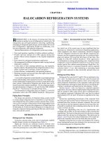
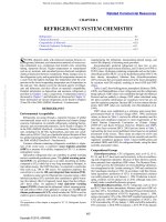
Figure 1 shows a double-gravity system with grains stored at the
39.1
Copyright © 2010, ASHRAE
This file is licensed to Abdual Hadi Nema (). License Date: 6/1/2010
39.2
2010 ASHRAE Handbook—Refrigeration (SI)
Licensed for single user. © 2010 ASHRAE, Inc.
Fig. 1 Brewery Flow Diagram
Table 1 Total Solids in a Cubic Metre of Wort at 10°C
%
Solids*
Total Density,
kg/m3
Mass of Solids,
kg
Specific Heat,
kJ/(kg ·K)
0
1
2
3
4
5
999.6
1003
1007
1011
1015
1019
0.0
10.0
20.1
30.3
40.6
51.0
4.19
4.16
4.13
4.10
4.07
4.04
6
7
8
9
10
1023
1027
1031
1036
1040
61.4
71.9
82.5
93.2
104.0
4.01
3.98
3.95
3.92
3.89
11
12
13
14
15
1044
1048
1052
1057
1061
114.8
125.8
136.8
147.9
159.1
3.86
3.84
3.81
3.78
3.75
16
17
18
19
20
1065
1070
1074
1078
1083
170.4
181.8
193.3
204.9
216.6
3.72
3.69
3.66
3.63
3.60
*Saccharometer readings.
Fig. 1 Brewery Flow Diagram
top of the brewhouse. As processing continues, gravity creates a
downward flow. Hot wort from the bottom of the brewhouse is
then pumped to the top of the stockhouse, where it is cooled and
again proceeds by gravity through fermentation and lagering.
After the wort cools, yeast and sterile air are injected into it. The
yeast is pumped in as a slurry at a rate of 4 to 12 g of slurry per litre
of wort. Normally, oil-free compressed air is filtered and treated
with ultraviolet light and then added to the wort, which is nearly saturated with approximately 11 mg/kg of oxygen. However, the wort
may also be oxygenated with pure oxygen.
Fermentation takes place in two phases. During the first phase,
called the respiratory or aerobic phase, the yeast consumes the oxygen present. It uses a metabolic pathway, preparing it for the anaerobic fermentation to follow. The process typically lasts 6 to 8 h.
Oxygen depletion causes the yeast to start anaerobically metabolizing the sugars in the extract, releasing heat and producing CO2
and ethanol as metabolic by-products.
During early fermentation, the yeast multiplies rapidly then more
slowly as it consumes the available sugars. Normal multiplication
for the yeast is approximately 3 times. A representative value for the
heat released during fermentation is 650 kJ/kg of extract (sugar) fermented.
Wort is measured by the saccharometer (measures sugar content), which is a hydrometer calibrated to read the percentage of
maltose solids in solution with water. The standard instrument is the
Plato saccharometer, and the reading is referred to as percentage of
solids by saccharometer, or degrees Plato (°P). Table 1 illustrates the
various data deducible from reading the saccharometer.
The same instrument is used to check fermentation progress.
Although it still gives an accurate measure of density of the fermenting liquid, it is no longer a direct indicator of dissolved solids
because the solution now contains alcohol, which is less dense than
water. This saccharometer reading is called the apparent extract,
which is always less than the real extract (apparent attenuation is
calculated from the hydrometer reading of apparent extract and the
original extract). In engineering computations, 81% of the change
in apparent extract is considered a close approximation of the
change in real extract. Thus, 81% of the difference between the solids shown in Table 1 for saccharometer readings before and after
fermentation represents the mass of maltose fermented. This mass
(in kilograms per cubic metre of wort at 10°C) times 650 kJ/kg gives
the heat of fermentation. The difference between the original solids
and mass of fermented solids gives the residual solids per cubic
metre. It is assumed that there is no change in the volume because
of fermentation. The specific heat of beer is assumed to be the same
as that of the original wort, but the mass per unit volume decreases
according to the apparent attenuation.
Bottom-fermentation yeast (e.g., Saccharomyces uvarium,
formerly carlsbergensis) is used in fermenting lager beer. Topfermentation yeast (e.g., Saccharomyces cerevisiae) is used in making
ale. They are so called because, after fermentation, one settles to the
bottom and the other rises to the top. A more significant difference
between the two types is that in the top-fermentation type, the fermenting liquid is allowed to attain a higher temperature before a
continued rise is checked. The following characteristics of brewing
ale make it different from brewing lager:
• A more highly kilned darker malt is used.
• Malt forms a greater proportion of the total grist (less adjunct).
• Infusion mashing is used and a wort of higher original specific
gravity is generally produced.
• More hops are added during the kettle boil.
• A different yeast and temperature of fermentation are used.
Therefore, ale may have a somewhat higher alcohol content and
a fuller, more bitter flavor than lager beer. With bottom-fermentation
yeasts, fermentation is generally carried out between 7 and 18°C
and most commonly between 10 and 16°C. Ale fermentations are
generally carried out at somewhat higher temperatures, often peaking in the range of 21 to 24°C. In either type, the temperature during fermentation would continue to rise above that desired if not
checked by cooling coils or attemperators, through which a cooling
This file is licensed to Abdual Hadi Nema (). License Date: 6/1/2010
Beverages
39.3
medium such as propylene glycol, ice water, brine, or ammonia is
circulated. In the past, these attemperators were manually controlled, but more recent installations are automatic.
PROCESSING
Licensed for single user. © 2010 ASHRAE, Inc.
Wort Cooling
To prepare boiling wort from the kettle for fermentation, it must
first be cooled to a temperature of 7 to 13°C. To avoid contamination
with foreign organisms that would adversely affect subsequent fermentation, cooling must be done as quickly as possible, especially
through the temperatures around 38°C. Besides the primary function of wort cooling, other beneficial effects accrue that are essential
to good fermentation, including precipitation, coagulation of proteins, and aeration (natural or induced, depending on the type of
cooler used).
In the past, the Baudelot cooler was almost universally used
because it is easy to clean and provides the necessary wort aeration.
However, the traditional open Baudelot cooler was replaced by one
consisting of a series of swinging leaves encased within a removable
enclosure into which sterilized air was introduced for aeration. This
modified form, in turn, has virtually been replaced by the totally
enclosed heat exchanger. Air for aeration is admitted under pressure
into the wort steam, usually at the discharge end of the cooler. The
air is first filtered and then irradiated to kill bacteria, or it can be sterilized by heating in a double-pipe heat exchanger with steam. By
injecting 40 L of air per cubic metre of wort, which is the amount
necessary to saturate the wort, normal fermentation should result.
The quantity can be accurately increased or diminished as the subsequent fermentation indicates.
The coolant section of wort coolers is usually divided into two or
three sections. For the first section, a potable source of water is used.
The heated effluent goes to hot-water tanks where, after additional
heating, it is used for subsequent mashing and sparging in the brew
house. Final cooling is done in the last section, either by direct
expansion of the refrigerant or by means of an intermediate coolant
such as chilled water or propylene glycol. Between these two, a
third section may be used from which warm water can be recovered
and stored in a wash-water tank for later use in various washing and
cleaning operations around the plant.
Closed coolers save on space and money for expensive cooler
room air-conditioning equipment. They also allow a faster cooling
rate and provide accurate control of the degree of aeration. To
maintain good heat transfer, closed coolers may be flushed with hot
water between brews or circulated for a few minutes with cleaning
solutions. More thorough cleaning, perhaps done weekly, is accomplished by much longer periods of circulation with cleaning solutions, such as 2 to 4% caustic at 80°C. Reverse flow of the cleaning
solution may also be used to help dislodge deposits of protein,
hops, and other materials.
In selecting a wort cooler, consider the following:
• The cooling rate should allow the contents of the kettle to be
cooled in 1 or, at most, 2 h.
• The heat transfer surfaces to be apportioned between the first section, using an available water supply, and the second section,
using refrigeration, should make the most economical use of each
of these resources. Cost of water, its temperature, and its availability should be balanced against the cost of refrigeration. Usual
design practice is to cool the wort in the first section to within 6 K
of the available water.
• Usable heat should be recovered (effluent from the first section is
a good source of preheated water). After additional heating, it can
be used for succeeding brews and as wash water in other parts of
the plant. At all times, the amount of heat recovered should be
consistent with the overall plant heat balance.
• Meticulous sanitation and maintenance costs are important.
Wort cooler size is determined by the rate of cooling desired, rate
of water flow, and temperature differences used. A brew, which may
vary in size from 5 to 100 m3 and over, is ordinarily cooled in 1 or,
at most, 2 h. Open coolers are made in stands up to about 6 m long.
Where more length is needed, two or more stands are operated in
parallel.
Open coolers are best operated with a wort flow of 10.7 to 12 L/s
per metre of stand. As flow increases beyond this rate, an increasingly larger part of the wort splashes from the top tube of the
cooler and drops directly into the collecting pan below without
contacting the cooler surfaces. An increased amount of wort flowing over the surfaces must be subcooled to offset what has been
bypassed.
In plate coolers, this bypassing does not occur, and wort velocities can be increased to a point where friction pressure through the
cooler approaches the maximum design pressure of the press and
gasketing. The number of passes and streams per pass afford the
designer much latitude in selecting the most favorable parameters
for optimum performance and economical design. This design is
based on (1) the specific heat of wort, (2) its initial temperature and
range through which it is to be cooled, (3) temperature of the available water supply, and (4) ratio of the quantity of cooling water to
wort that is to be used. Design and operating features of a typical
plate cooler are as follows:
Specifications
Quantity of wort to be cooled
Temperature of hot wort
Temperature of cooled wort
Temperature of available water (maximum)
Water used, not to exceed
Temperature of water leaving cooler
Temperature of wort leaving first section of cooler
Temperature of incoming recirculated chilled water
2.14 kg/s
98°C
4°C
21°C
4.28 kg/s
60°C
27°C
1°C
Plate cooler (first section)
Number of plates
Heat transfer surface per plate
Heat transfer surface in first section
Number of passes
Number of streams per pass
Water flow rate
Wort flow rate
40
0.4 m2
16 m2
5
4
4.28 kg/s
2.14 kg/s
Plate cooler (second section)
Number of plates
Heat transfer surface per plate
Heat transfer surface in second section
Number of passes
Number of streams per pass
Chilled-water flow rate
24
0.4 m2
9.6 m2
3
4
6.5 kg/s
A shell-and-tube or plate cooler with two stages of cooling can
cool the wort efficiently. In the first (hot) stage, potable water is used
counterflow to the wort, and the usual discharge temperature is
about 76 to 77°C. This hot water is then used in the following brews
at various blended temperatures. Excess is used in the brewery’s
general operations.
The second stage of wort cooling is accomplished at about 2°C
by a closed system of refrigerated water through a closed cooler,
which cools the wort to 10°C or lower, depending on the brewer.
Lower-temperature water (1°C) may be used in open units where no
danger of freezing exists.
Wort cooling may be accomplished in one stage, depending on the
potable water temperature available and plant refrigeration capacity.
If chilled water (0.5 to 2°C) is available, water use is typically 1.1 to
1.4 times the volume of wort and exits the cooler at temperatures
This file is licensed to Abdual Hadi Nema (). License Date: 6/1/2010
39.4
2010 ASHRAE Handbook—Refrigeration (SI)
suitable for immediate use in brewing. If ambient water is used, much
larger volumes are required and water costs must be considered.
Also, excess hot water may be sewered, leading to increased waste
effluent charges.
Fermenting Cellar
After cooling, the wort is pitched with yeast and collected in a fermenting tank, where respiration and fermentation occur according to
the chemical reaction previously discussed. The daily rate of fermentation varies depending on the operating procedure adopted in each
plant. On the first day, a representative rate might be 8 kg of converted maltose per cubic metre of wort. The rise in temperature
caused by fermentation and by the growth and changing physiology
of the yeast increases this rate to 27 kg/m3 on the second day. By
now, the maximum desired temperature has been attained, and a further rise is checked by an attemperator, so that on the third day
another 27 kg/m3 is converted. This rate continues through the fourth
day. Two examples of the fermentation rate follow; one is for normalgravity brewing, and the other is for high- (heavy) gravity brewing.
Example 1 Normal-Gravity Brewing
Licensed for single user. © 2010 ASHRAE, Inc.
Fermentation
Day
0
1
2
3
4
5
°Plato
11
10
8
5
3
2.5
Real
Extract
Mass of
Extract,
kg/m3
11.0
10.2
8.6
6.1
4.5
4.1
114.5
105.8
88.7
62.3
45.7
41.6
Extract
Fermented,
kg/m3
—
8.70
17.12
26.40
16.66
4.10
72.98
Example 2 High-Gravity Brewing
Fermentation
Day
0
1
2
3
4
5
°Plato
Real
Extract
Mass of
Extract,
kg/m3
16
15
12
7
4
3.5
16.0
15.2
12.8
8.7
6.3
5.9
170.0
161.0
134.2
89.3
64.4
60.2
Extract
Fermented,
kg/m3
—
9.01
26.71
44.49
25.36
4.17
Most brewers cool beer to between 7 and 3°C after ending fermentation or after the final days of quick cooldown in the fermenting
tank. In addition, the long rest allows time for the yeast to settle.
Some brewers agitate the beer in cylindrical fermenters, which
enables them to ferment the beer faster and then to separate out the
yeast by centrifuge. Most brewers cool the beer to the desired –2 to
7°C temperature before it goes into storage for resting and settling
between fermentation and final aging.
Fermenting Cellar Refrigeration
The agitation necessary for heat exchange between the attemperator and the beer is provided partly by convection resulting from temperature gradients in the beer. Agitation is principally by the
ebullition caused by the carbon dioxide (CO2) bubbles rising to the
surface of the liquid. In estimating the heat transfer surface required,
a heat transfer rate range from 85 to 170 W/(m2 ·K) is reasonable.
Heat loss from tank walls and the surface of the liquid may be disregarded when calculating attemperator coil surface requirements.
However, if the room temperature drops appreciably below 10°C,
heat dissipated through the metal tank walls becomes important.
Depending on the degree of heat dissipation, fermentation may be
retarded or even inhibited. In such instances, insulating the fermenter
walls and bottom is required so that control over heat removal
remains in the attemperator.
Refrigeration requirements are based on the maximum volume
of wort being fermented, as illustrated by Example 3.
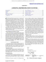
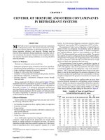
Example 3. Figure 2 illustrates the volume of wort production based on a
60 m3/day production rate. Days are represented by the abscissa, and
the kilograms of solids converted per cubic metre of beer by the ordinate. The individual brews in fermentation on any particular day are
additive. For example, on the fifth day, Brew no. 1 is finishing with a
conversion rate of 12 kg/m3 for that day; Brew no. 5, which is just
beginning the fermentation cycle, is fermenting at the rate of 8 kg/m3;
and Brews 2, 3, and 4 are each at the maximum rate of 28 kg/m3 per
day. The total solids fermented on this day are 104 kg/m3 for the
300 m3 in fermentation, totaling 6240 kg of solids converted per day
0.0722 kg/s. Because the heat of fermentation is 650 kJ/kg, the refrigeration load is
0.0722 650 = 46.9 kW
Calculations for sizing attemperators must consider the (1) internal
dimensions of the fermenting tank and its capacity; (2) temperature
109.74
By now, the amount of unconverted maltose remaining in the
beer is greatly diminished. Because alcohol, carbon dioxide, and
other products of fermentation inhibit further yeast propagation, the
action nearly stops on the fifth day, when only about 12 kg/m3 is
converted per cubic metre. At this stage the yeast begins to flocculate (clump together) and either settles to the bottom of the fermenter (bottom yeast) or rises to the top (top yeast). Because of the
reduced fermentation rate, the temperature of the beer begins to
fall, either as the result of increased attemperation applied to the
tank itself, heat loss from the tank to the surrounding area, or both.
Many fermentation programs call for the beer to be cooled to 2 to
7°C at this time. This period of more rapid cooling helps settle the
yeast. At the completion of this cooling period, the fermentation
rate is essentially zero, and the beer is ready to be transferred off the
settled yeast. Complete fermentation generally occurs in about
7 days. The introduction of new types of beers (e.g., reduced calorie, reduced alcohol) and the more general use of high-gravity
brewing have led to the use of a variety of fermentation programs
both between brewers making the same product and within the
same brewery for different products.
Complete fermentation can be accomplished in less than 7 days,
but most modern brewers take 7 to 10 days for the fermentation and
subsequent cooling. The time depends on original gravity, whether
a secondary fermentation is used, and available cooling capacity.
Fig. 2 Solids Conversion Rate
Fig. 2 Solids Conversion Rate
This file is licensed to Abdual Hadi Nema (). License Date: 6/1/2010
Beverages
39.5
difference between the coolant and fermenting beer; (3) maximum daily
sugar conversion rate; and (4) heat evolved, which is at the rate of
650 kJ/kg of fermentable sugar converted.
Assuming a square fermenting tank 4 m per side to hold a brew of
60 m3 and allowing 0.25 m between the tank wall and the attemperator
for easy cleaning, a 3.5 m attemperator can be used, giving 14 m of
tubing.
From Figure 2, the maximum daily conversion rate is 28 kg/m3.
Calculating for 60 m3 per day at 650 kJ/kg of sugar converted,
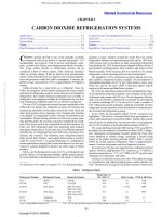
Fig. 3 Continuous Aging Gravity Flow
28 60 650/(24 3600) = 12.6 kW
Assuming a 10°C fermenting beer temperature and –7°C brine
(a temperature difference of 17 K and a heat transfer rate of 85 W/(m2 ·K)
for the attemperator, the surface area required is
12.6 1000/(85 17) = 8.72 m2
Considering 100 mm OD tubing with an external area of 0.314 m2/m,
the length required is
8.72/0.314 = 27.8 m
Licensed for single user. © 2010 ASHRAE, Inc.
Two attemperators (each 3.5 m square) give 28 m of tubing, which
is adequate for the conditions outlined.
Old attemperators usually consisted of one or more rings of 75 or
100 mm copper or stainless tubing, concentric with the walls of the
tank and supported at about two-thirds of the height of the liquid.
Almost all modern fermenter designs use exterior jackets for temperature control. The side wall of the fermenter may have two or three
individual jackets and the cone or bottom of vertical fermenters may
also have one or two small jackets. Each jacket uses a baffled flow or
dimple plate design that maintains good flow and good heat transfer
across all areas of the jacket. A glycol solution or liquid ammonia
may be circulated through the cooling jackets. These tank changes,
dictated by automation and economics, allow easier in-place tank
cleaning and provide more cooling effect in fermenting.
Stock Cellar
The stock cellar may be a refrigerated room containing storage
tanks that do not have any cooling capacity, or it may be an ambient
room containing storage tanks with exterior jackets or interior cooling surfaces. Cooled beer from fermentation is transferred into these
tanks for aging or maturing, as the process is sometimes called.
Some brewers prefer some yeast carry-over into aging, so they simply transfer the fermented beer into the stock cellar tanks. Other
brewers do not want as much (or perhaps no) yeast carry-over. Storage residence time varies, depending on the wishes of the brewer.
Typical residence times for modern breweries range from 5 to
15 days, but much longer times may be used. Under cold-storage
conditions, slow, subtle chemical changes take place that are very
important to the final flavor and aroma profile of the beer or ale.
Physical changes, such as precipitation of insoluble proteins, also
occur. These changes are important for preventing haze formation in
the finished product.
Modern aging tanks are normally pressurized with carbon dioxide to prevent air from coming into contact with the aging beer. For
stock cellars that use storage tanks that are vented to the atmosphere, adequate provision must be made to supply fresh air in
sufficient amounts to keep the CO2 concentration below 0.5%. Airconditioning equipment, using chemical dehumidification and
refrigeration, is generally used to maintain dry conditions such as
0°C and 50% rh in storage areas. This decreases mold growth and
rusting of steel girders and other steel structures. To maintain
lower CO2 concentration in tightly closed cellars and to reduce operational cost, heat exchange sinks and thermal wheels are used to
cool incoming fresh air and to exhaust cold stale air.
Air compressor systems commonly use air driers with refrigerated aftercoolers, 0°C glycol coolers, desiccant drying, or a combination. This is necessary if lines pass through areas below 0°C.
Fig. 3 Continuous Aging Gravity Flow
A continuous aging process used in multistory buildings, all
gravity flow, is shown in Figure 4. This process is better for larger
operations that principally produce one brand of beer.
Kraeusen Cellar
Instead of carbonating the beer during the finishing step, some
brewers prefer to carbonate by the Kraeusen method. In this procedure, fully fermented beer is moved from the fermenting tank to a
tank capable of holding about 140 kPa (gage). A small percentage of
actively fermenting beer is added. The tank is allowed to vent freely
for 24 to 48 h, then is closed and the CO2 pressure allowed to build.
Because the amount of CO2 retained in the beer is a function of temperature and pressure, the brewer can achieve the desired carbonation level by controlling either or both pressure and temperature.
After Kraeusen fermentation, generally a week or more, the beer
may be moved to another storage tank. However, the brewer can
accomplish the same effect by leaving the beer in the Kraeusen tank
and cooling the beer by space cooling, tank coils, or both.
Heat is generated by this secondary fermentation, but the temperature of the liquid does not rise as high as it did in the fermenter
because fermentable sugars are only available from the small percentage of actively fermenting beer, added as Kraeusen. Furthermore, the bulk of the liquid may have a lower starting temperature
than in primary fermentation. Typically, a temperature of 4 to 10°C
may be reached at the peak, after which the liquid cools to the ambient temperature of the room. This cooling can be accelerated in the
tanks by circulating a cooling liquid, such as propylene glycol,
through attemperators. Because heat is generated during Kraeusen
fermentation, refrigeration load calculations must include removal
of this heat by transfer to air in the cellar, by tank coils, or by a combination of both. Furthermore, if the tank is to be used as a storage
tank, the calculation must include the necessary heat removal to
reduce the beer temperature to the desired level.
Finishing Operations
After flavor maturation and clarification in the storage tanks, the
beer is ready for finishing. Finishing includes carbonation, stabilization, standardization, and clarification.
Carbonation. Any of the following processes are used to raise
the CO2 concentration from 1.2 to 1.7 volumes/volume to about
2.7 volumes/volume:
This file is licensed to Abdual Hadi Nema (). License Date: 6/1/2010
39.6
•
•
•
•
•
Kraeusen
In-line
In-tank with stones
Saturator
Aging train
Stabilization. The formation of colloidal haze, caused by soluble proteins and tannins forming insoluble protein/tannin complexes, is reduced by any of the following materials:
Licensed for single user. © 2010 ASHRAE, Inc.
•
•
•
•
Enzymes (papain)
Tannic acid
Tannin absorbents
Protein absorbents, silica gel, bentonite
Standardization. Chilled, deaerated, and carbonated water is
added to adjust original density from high-density level (14 to
16° Brix) down to normal package levels (10 to 12° Brix or lower
for diet beer).
Clarification. In the finishing cellar, beer is polished by filtration
and is then carbonated by any of several methods. Filtering is normally done with an easily automated diatomaceous earth (DE) filter.
Some cellulose pulp filters and sheet filters are still used, but they
require more labor. After the filtration step, frequently a cartridgetype filter is used to trap any particles that may still be present.
Recently, various types of cartridges and membranes have been used
to produce products that are essentially sterile. The number of filters
used depends on the brilliance desired in the finished product. After
this final processing, beer is transferred to the government cellar and
held until it is needed for filling kegs in the racking room or bottles
or cans in the packaging plant. In some breweries, initial clarification
is accomplished using centrifuges. This reduces the load on the filtration system, allowing higher flow rates and longer filter runs.
Outdoor Storage Tanks
Some breweries use vertical outdoor fermenting and holding
tanks (similar to those popular with dairies). These tanks have
working capacities of 250 to 1200 m3. The geometry of these tanks
includes a conical bottom and height-to-diameter ratios from 1:1 to
5:1. The tanks are jacketed and use propylene glycol or the direct
expansion of ammonia for cooling. Insulation is usually 100 to
150 mm thick polyurethane foam with a stainless steel cladding.
They may be built as fermenters or as aging tanks, or in many
cases, the same tank may serve for both fermenting and aging, with
no beer transfer.
Hop Storage
If raw hop cones are used, they should be stored at a temperature
of 0 to 1°C with 55 to 65% rh and very little air motion to prevent
excessive drying. Sweating of the bales should not be permitted
because this would carry off the light aromatic esters and deteriorate
the fine hop character. Nothing else should be stored in the hops
cellar because foreign odors may be absorbed by the hops, which
would result in off-flavors in the beer. Hops pellets are packed in airtight, sealed containers, but should be stored near or below 0°C to
prevent flavor and aroma deterioration. Hop extracts are generally
very stable and may be stored at ambient temperatures.
Yeast Culture Room
In the yeast culture room, yeast is propagated to be used in
reseeding and replacing yeast that has lost its viability. Normal fermentation of aerated wort also propagates yeast. The amount of
yeast roughly triples during fermentation, depending on the degree
of aeration. A portion of this yeast is repitched (reused) in later fermentation, and the balance is discarded as waste yeast, which is
sometimes sold for other purposes. Clean yeast, usually the middle
layer of the yeast deposit that remains in a fermenting tank after
removal of the beer, is selected for repitching.
2010 ASHRAE Handbook—Refrigeration (SI)
Repitched yeast is carefully handled to avoid contamination with
bacteria and is stored in the yeast room as a liquid slurry (yeast balm)
in suitable vats. If open vats are used, 80% rh is required to prevent
the yeast from hardening on the vat walls. The CO2 blanket on top of
the vats should not be disturbed by excessive air motion. There is
considerable variation in yeast handling and recycling practices.
PASTEURIZATION
Plate pasteurizers heat beer to a temperature sufficient for proper
pasteurization (15 s at 71°C or 10 s at 74°C) and then cool the pasteurized product with incoming cold beer. Plate pasteurizers and
microfiltration are used to produce a beer that is similar to draft beer
but does not require refrigeration to prevent spoilage. It is distributed in bottles and cans that can be of slightly lighter construction
because they do not have to withstand the high pressure created in
tunnel pasteurizers.
CARBON DIOXIDE
The amount of CO2 produced per litre of wort depends on the
original gravity (starting sugar concentration) and the final gravity
of the beer (ending sugar concentration). Depending on the type of
fermenter and amount of free head space at the start of fermentation,
over 75% of this gas may be collected, purified, and liquefied for
later use in the brewery. In addition to carbonating the beer to the
proper level, CO2 is also used to purge air from tanks, to push beer
from one tank to another, for pressure in tanks of beer, and for operating bottle, can, and keg lines.
Decades ago, open-top fermenters were common. Carbon dioxide
from fermentation filled the fermenting room and was a serious health
hazard. Concentrations below 0.5% were generally considered to be
safe for the operators, but higher concentrations reduced a worker’s
efficiency. Concentrations between 4 and 5% were considered too
dangerous to work in for more than a minute or two. Because carbon
dioxide is heavier than air, it tends to settle to the floor. Fermenting
rooms were constructed with outlets near the floor where the elevated
concentrations of carbon dioxide could be withdrawn. Fresh air inlets
were located at the upper levels of the room.
Almost all modern breweries now use fully closed fermentation
tanks. Not only do these closed tanks protect the process from accidental contamination, but all carbon dioxide can be either vented
outside of the room, or directed to a collection system. As federal
and state regulation became more common, very strict safety standards were adopted for exposure to carbon dioxide in the working
areas. To comply with these standards and avoid potential penalties
from agencies such as the Occupational Safety and Health Administration (OSHA), many modern breweries now use monitoring systems to detect elevated concentrations of carbon dioxide in the
various enclosed work areas in the brewery.
Collection
Carbon dioxide gas, produced as a by-product of fermentation,
can be collected from closed fermenters, compressed, and stored in
pressure tanks for later use. It may be used for final carbonation,
counterpressure in storage and finishing tanks, transfer, and bottling
and canning. In the past, the CO2 was stored in the gaseous state at
about 1.8 MPa. Today, however, in most medium and large breweries, the gas is collected and, after thorough washing and purification, it is liquefied and stored. Carbon dioxide stored in the liquid
state occupies about 2% of the volume of an equal mass of gas at the
same pressure at room temperature.
As an example, from each cubic metre of wort fermented, about
50 kg of CO2 is generated over a period of five days, though not at
a constant daily rate. Therefore, brews must be carefully scheduled
to provide the necessary CO 2 gas, thereby minimizing storage
requirements. As a general rule, only about 50 to 60% of the total
gas generated is collected. Gas generated at the beginning and end
This file is licensed to Abdual Hadi Nema (). License Date: 6/1/2010
Beverages
39.7
Licensed for single user. © 2010 ASHRAE, Inc.
of the fermentation cycle is discarded because of excessive air content and other impurities.
From the fermenting tank, the gas is piped through a foam trap
to a gas-pressure booster. Surplus gas is discharged to the outside
from a water-column safety relief tank, which also protects the fermenting tank from excessive gas pressure. To compensate for friction pressure loss in the long lines to the compressor and to
increase its capacity, the booster raises the pressure from as low as
0.25 to 30 to 40 kPa (gage).
Compressors, which in the past were two-stage with water injection, are being replaced by nonlubricated compressors that use carbon or nonstick fluorocarbon rings. Today, lubricated screw and
reciprocating compressors are used for food and beverage-grade
CO2 production in commercial CO2 plants and in some large breweries. These may be single two-stage compressors or two compressors comprising individual high and low stages. A complete
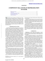
collection system consists of suction and foam trap; rotary boosters,
where required; scrubber; deodorizer; compressor (or compressors); intercoolers and aftercoolers; dehumidifying tower; condenser (with refrigeration from a separate system to ensure that no
CO2 enters the main system through leaks); liquid storage tanks;
and vaporizers, all interconnected and automatically controlled.
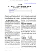
Fig. 4 Typical Arrangement of CO2 Collecting System
Liquefaction
The condensing pressures of carbon dioxide at several temperatures are
–30°C
–25°C
–20°C
1.43 MPa
1.68 MPa
1.97 MPa
The latent heat at saturation temperature is about 280 kJ/kg.
The refrigerant for liquefying the compressed gas should be about
–30°C to condense the CO2 effectively. Most of the moisture must
be removed from the compressed gas; this may be done by passing the gas through a horizontal-flow finned coil (located in a 2°C
cellar), which condenses out about 80% of the moisture (i.e., the
condensate is drained from the system. Also, this is done effectively with refrigerant-cooled precoolers, intercoolers, and aftercoolers. Sending the gas through desiccant driers removes
additional moisture. The emerging gas has a slightly higher temperature, but has a dew point around –57°C or lower.
Under these conditions, gas is liquefied when it comes in contact
with the liquefying surfaces, which stay ice-free because of the low
moisture content (–40°C dew point) of the gas, thus ensuring continuous service. Dryers are installed in duplicate with automatic
timing for regeneration of the desiccant material. Desiccant dryers
usually rely on heated CO2 as the regeneration gas. An earlier
method used dual sets of double-pipe dryers, which froze out moisture and retained it in the heat exchanger.
Liquefiers are vertical shell-and-tube, inclined double-pipe, or
shell-and-tube types. The refrigerant side is operated fully flooded,
with refrigerant supplied from a system separate from the main system. Carbonating systems have changed with all-closed fermenters,
refrigerated condensing systems, and large liquid CO2 holding tanks.
See Figure 4 for collecting and liquefaction system flow diagrams.
CO2 Storage and Reevaporation
Condensed CO2 drains into a storage tank, which is usually
designed for a working pressure of 2.1 MPa and varying storage
capacities of 4.5 to 54 Mg each. The vessel is insulated and is
equipped with equalizing connections, safety valves, liquid-level
indicators, and electric heating units. Gas purity tests are regularly
conducted from samples withdrawn from above the liquid level.
As liquid is withdrawn from the tank, it is introduced to a steamheated liquid vaporizer, which is automatically controlled to give
the desired superheat to the vaporized gas. This type of vaporizer is
now replacing other types because of its ability to control the
Fig. 4 Typical Arrangement of CO2 Collecting System
temperature of CO2 gas. Vaporized gas is directed to large, highpressure surge tanks, where the pressure may be over 1400 kPa.
Carbon dioxide from these tanks passes through pressure reduction
valves to supply the brewery with gas that normally ranges from
550 to 690 kPa.
HEAT BALANCE
Most of the steam required for processing, heating water, and
general plant heating can be obtained as a by-product. Because the
manufacture of beer is a batch process with various peaks occurring
at different times, the study of the best heat balance possible is difficult. In a given plant, it depends on many variables, and a comprehensive study of all factors is necessary.
In brewery plant locations where electric energy costs are high,
installation of cogeneration facilities can be favorable. However, in
plants that produce more than 350 000 m3 annually, the steam turbine as a prime mover often comes into prominence. A bleeder
steam turbine operating at 2.8 MPa can be used to drive a refrigeration compressor, electrical generator, or both; steam bled from it
can be used for process and other needs requiring low-pressure
steam. In smaller plants, less favorable heat balances must be accepted in line with more economical plant investment programs.
Each brewery requires individual study to develop the most economical program.
Many process steam loads are highly variable; for example, the
brew kettle’s warm-up cycle (both equipment mass and the content’s
mass) requires three to five times as much steam as brewing does.
Steam plant (boiler) sizing is significantly affected by this changeability. Initial boiler size/capacity can be reduced by installing a heat
storage tank (e.g., for brewing water) that can be heated over a longer
period of time, thus reducing the dynamic peak load required at batch
start-up.
COMMON REFRIGERATION SYSTEMS
Absorption Machine for Heat Balance (especially for air conditioning and water cooling for wort cooling). The unit requires a
This file is licensed to Abdual Hadi Nema (). License Date: 6/1/2010
Licensed for single user. © 2010 ASHRAE, Inc.
39.8
2010 ASHRAE Handbook—Refrigeration (SI)
careful heat balance study to determine whether it is economical.
These machines may be a good selection if excess 140 kPa (gage)
steam (single-effect) or 760 kPa (gage) steam (double-effect) is available.
Halocarbon Refrigerant Cascade System. Oil-free ammonia
as brine can be pumped at a 1:1 ratio with water. The ratio of motive
power to refrigeration at 170 and 1270 kPa (gage) is 0.30 kW/kW.
Direct Centrifugal. This is often an oil-free ammonia system
with a 1:1 ratio with water. The unit requires pumps. This is usually
the most expensive and least efficient of these systems.
Oil-Sealed Screw Compressors. Ammonia is circulated at a 1:1
ratio in this system. The units require pumps. The ratio of motive
power to refrigeration is 0.27 kW/kW. This is probably the least
expensive system.
Oil-Free Compressors, Screw Type. The ratio of motive power
to refrigeration is 0.32 kW/kW. System noise levels can be high.
Large Balanced Opposed Horizontal Double-Acting Reciprocating Compressor. While the system is not oil-free, good oil
separation equipment minimizes this problem. It can use recirculation or direct expansion. The ratio of motive power to refrigeration
is 0.26 kW/kW. This system requires the most maintenance, and can
be the most expensive.
Further automation has been accomplished by programming the
flow of materials in the brewhouse, as well as the entire brewing
operation. The newest brewing operations are fully automated.
Where necessary, a cooling tower may be used to reduce thermal
pollution or to conserve water in the pasteurizing phase. Ecology
plays an important part in the brewery; stacks are monitored for
particulates, effluent is checked, and heat from kettle vents and others is recovered. Water use is more closely regulated, and refrigeration systems use water-saving equipment, including evaporative
condensers.
Food-Grade Brines. Some of the cooling temperatures (e.g.,
ingredient water required for finished product mixing from heavygravity brewing) are near freezing, thus requiring coolant temperatures
below freezing and consequently the necessary brine in the coolant. In
food and beverage facilities, this brine should be food-grade propylene
glycol so that minor leaks (e.g., heat exchanger pinholes) into the ingredient will not render the finished product nonsalable. If other plant
systems require brine solutions, they should also use food-grade propylene glycol to eliminate the chance of injecting a non-food-grade
brine into a food-grade system.
VINEGAR PRODUCTION
Vinegar is produced from any liquid capable of first being converted to alcohol (e.g., wine, cider, malt) and syrups, glucose,
molasses, and the like.
First Stage: Conversion of sugar to alcohol by yeast (anaerobic)
C6H12O6 2CH3CH2OH + 2CO2
Second Stage: Conversion of alcohol to acetic acid by bacterial
action (aerobic)
CH3CH2HO + O2 CH3COOH + H2O
Bacteria are active only at the surface of the liquid where air
is available. Two methods are used to increase the air-to-vinegar
surface:
The packed (or Frings) generator is a vertical cylinder with a
perforated plate and is filled with oak shavings or other inert support
material intended to increase column surface area. The weak alcohol and vinegar culture are introduced, and the solution is continuously circulated through a sparger arm, with air introduced through
drilled holes in the top of the tank. A heat exchanger is used to
remove the heat generated and to maintain the solution at 30°C. This
is a batch process requiring 72 h.
In submerged fermentation, air is distributed to the bacteria
by continuously disbursing air bubbles through the mash in a tank
filled with cooling coils to maintain the 30°C temperature. This
also is a batch process, requiring 39 h.
Concentration is best accomplished by removing some of the
water in the form of ice, which increases the acid concentration by
12 to 40%. In freezing out water, a rotator is often used. About –18
to –12°C is required on the evaporating surface to produce the best
crystals; the ice is separated in a centrifuge. The vinegar is then
stored 30 days before filtering. Effective concentration can also be
achieved by distillation (as is done for distilled white vinegar).
WINE MAKING
The use of refrigeration to control the rates of various physical,
chemical, enzymatic, and microbiological reactions in commercial
wine making is well established. Periods at elevated temperatures,
followed by rapid cooling, can be used to denature oxidative
enzymes and proteins in grape juices, to retain desirable volatile
constituents of grapes, to enhance the extraction of color pigments
from skins of red grapes, to modify the aroma of juices from certain white grape cultivars, and to inactivate the fungal populations
of mold-infected grapes. Reduced temperatures can slow the
growth rate of natural yeast and of the enzymatic oxidation of certain phenolic compounds, assist in the natural settling of grape solids in juices, and favor the formation of certain by-products during
fermentation. Also, reduced temperatures can be used to enhance
the nucleation and crystallization of potassium bitartrate from
wines, to slow the rate of aging reactions during storage, and to
promote the precipitation of wood extractives of limited solubility
from aged brandies.
The extent to which refrigeration is used in these applications
depends on factors such as the climatic region in which the grapes
were grown, the grape cultivars used, physical condition of the
fruit at harvest, styles and types of wines being produced, and the
discretion of the winemaker.
Presently, the wine industry in the United States is heavily committed to the production of table wines (ethanol content less than
14% by volume). Considerably less emphasis is being placed on
the production of dessert wines and brandies than in the past.
Additionally, the recent growth in wine cooler popularity has significantly altered winery operations where they are produced. A
variety of enological practices and winery equipment can be found
between the batch emphasis of small wineries (crushing tens of
tonnes per season) and the continuous emphasis of large wineries
(crushing hundreds or thousands of tonnes per season).
The applications of refrigeration will be classified and considered in the following order:
1.
2.
3.
4.
5.
6.
7.
8.
Must cooling
Heat treatment of red musts
Juice cooling
Heat treatment of juices
Control of fermentation temperature
Potassium bitartrate crystallization
Control of storage temperatures
Chill-proofing of brandies
MUST COOLING
Must cooling is the cooling of crushed grapes before separating
the juice from the skins and seeds. White wine grape musts will
often be cooled before being introduced to a juice-draining system
or a skin-contacting tank; this is done to reduce the rate of oxidation
of certain juice components, as well as to prevent the onset of spontaneous fermentation by wild and potentially undesirable organisms. Must cooling can be used when grapes are delivered to the
This file is licensed to Abdual Hadi Nema (). License Date: 6/1/2010
Beverages
39.9
winery at excessively high temperatures or when they have been
heated to aid in pressing or extracting red color pigments.
In general, tube-in-tube or spiral heat exchangers are used.
Tubes of at least 100 mm internal diameter with detachable end
sections of large-radius return bends are necessary to reduce the
possibility of blockage by any stems that might be left in the must
after the crushing-destemming operation. The cooling medium
can be chilled water, a glycol solution, or a directly expanding
refrigerant. Overall heat transfer coefficients for must cooling
range between 400 and 700 W/(m2 ·K), depending on the proportions of juice and skins, with the must side providing the controlling resistance. In small wineries, jacketed draining tanks and
fermenters are often used to cool musts in a relatively inefficient
batch procedure in which the overall coefficients are on the order
of 10 to 30 W/(m2 ·K) because the must is stationary and, therefore, rate-controlling.
believe, enhance the varietal aroma of certain juices. Denaturation
of proteins reduces the need for their removal (by absorptive clays
such as bentonite) from the finished wine. However, turbid juices
and wines can result from this treatment, presumably because of
modification of the pectin and polysaccharide fraction. Clarified
juices from mold-infected grapes can be treated in a similar way to
denature oxidative enzymes and to inactivate the molds. Most wineries in the United States rely on “pure culture” fermentation to
achieve consistently desirable results; hence the value of HTST
treatment in the control of microbial populations.
A typical program includes rapidly raising the juice temperature
to 90°C, holding it for 2 s, and rapidly cooling it to 15°C. Plate heat
exchangers are used because of their thin film paths and high overall
coefficients. Grape pulp and seeds can cause problems in this equipment if they are not completely removed beforehand.
FERMENTATION TEMPERATURE CONTROL
Licensed for single user. © 2010 ASHRAE, Inc.
HEAT TREATMENT OF RED MUSTS
Most red grapes have white or greenish-white flesh (pulp) and
juice. The coloring matter or pigments (anthocyanins) reside in the
skins. Color can be rapidly extracted from these varieties by heat
treating musts so that the pigment-containing cells are disrupted
before actual fermentation. This process is done in several countries throughout the world when grape skins are low in color or
when color extraction during fermentation is poor. Must heating is
necessary to produce the desirable flavor profile of some varieties,
most notably Concord, when manufacturing juices, jellies, and
wines. The series of operations is referred to as thermovinification.
The must is heated to temperatures in the range of 57 to 75°C, generally by draining off some of the juice, condensing steam, and
returning the hot juice to the skins for a given contact time, often
30 min. The complete must can be cooled before separation and
pressing, or the colored juice can be drawn off and cooled prior to
the fermentation.
Heat treatment can also be used to inactivate the more active oxidative enzymes found in red grapes infected by the mold Botrytis
cinerea. It can further aid the action of pectic enzyme preparations
added to facilitate pressing of some cultivars. In all cases, the temperature/time pattern used is a compromise between desirable and
undesirable reactions. The two most undesirable reactions are caramelization and accelerated oxidation of the juice. Condensing steam
and tube-in-tube exchangers are generally used for these applications, with design coefficients similar to those given previously for
must cooling.
JUICE COOLING
Juices separated from the skins of white grapes are usually
cooled to between 2 and 20°C to aid natural settling of suspended
grape solids, to retain volatile components in the juice, and to prepare it for cool fermentation. Tube-in-tube, shell-and-tube, and
spiral exchangers and small jacketed tanks are used with either
direct expansion refrigerant, propylene glycol solution, or chilled
water as the cooling medium. Overall coefficients for juice cooling
range between 550 and 850 W/(m2 ·K) for the exchanger and 25 to
50 W/(m2 ·K) for small jacketed tanks.
The small jacketed tank values can be improved significantly by
juice agitation. Transport and thermal properties of 24% (by mass)
sucrose solutions can be used for grape juices. There is a general
tendency for medium and large wineries to use continuous-flow
juice cooling arrangements of jacketed tanks.
HEAT TREATMENT OF JUICES
Juices from sound grapes can be exposed to a high-temperature,
short-time (HTST) treatment to denature grape proteins, reduce
the number of unwanted microorganisms, and, some winemakers
Anaerobic conversion of grape sugars to ethanol and carbon dioxide by yeast cells is exothermic, although the yeast is capturing a
significant quantity of the overall energy change in the form of highenergy phosphate bonds. Experimental values of the heat of reaction
range between 83.7 and 100.5 kJ/mole, with 99.6 kJ/mole being
generally accepted for fermentation calculations (Bouffard 1985).
One litre of juice at 262 kg/m3 sucrose (24° Brix) will produce
approximately 60 L of carbon dioxide during fermentation. Allowing for the enthalpy lost by this gas, with its saturation levels of
water and ethanol vapors, the corrected heat release value is
95.9 kJ/mole at 15°C and 88.3 kJ/mole at 25°C. The adiabatic temperature rise of the 262 kg/m3 juice would then be 48.3°C, based on
the 15°C value, and 45.6°C, based on the 25°C value. Whether a
fermentation approaches these adiabatic conditions depends on the
difference between the rate of heat generation by fermentation and
the rate of heat removal by the cooling system. For constanttemperature fermentations, which are the most common type of
temperature control practiced, these rates must be equal. Red wine
fermentations are generally controlled at temperatures between 24
and 32°C, whereas white wines are fermented at 10, 15, or 20°C,
depending on the cultivar and type of wine being produced. The
more rapid fermentations of red wines are used in the cooling load
calculations of individual fermenters; a more involved composite
calculation, allowing for both red and white fermentations staggered in time, is necessary for the overall daily fermentation loads.
At 20°C, red wines have average fermentation rates in the range
of 40 to 50 kg/m3 per day, which correspond to heat release rates of
approximately 217 to 270 W/m3 per hour. The peak fermentation
rate is generally 1.5 times the average, leading to values of 325 to
405 W/m3 per hour. This value, multiplied by the volume of must
fermenting, provides the maximum rate of heat generation. The heat
transfer area of the jacket or external exchanger can then be calculated from the average coolant temperature and overall heat transfer
coefficient.
The largest volume of a fermenter of given proportions, with fermentation that can be controlled by jacket cooling alone, is a function of the maximum fermentation rate and the coolant temperature.
The limitation occurs because the volume (and hence the heat generation rate) increases with the diameter cubed, whereas the jacket
area (and hence the cooling rate) only increases with the diameter
squared. Similarly, the temperature rise in small fermenters, cooled
only by ambient air, depends on the fermenter’s volume and shape
and the ambient air temperature (Boulton 1979a).
Development of a kinetic model for wine fermentations (Boulton
1979b) has made it possible to predict the daily or hourly cooling
requirements of a winery. The many different fermentation temperatures, volumes, and starting times can now be incorporated into algorithms that predict future demands and schedule off-peak electricity
usage, allowing for optimal control of refrigeration compressors.
This file is licensed to Abdual Hadi Nema (). License Date: 6/1/2010
Licensed for single user. © 2010 ASHRAE, Inc.
39.10
2010 ASHRAE Handbook—Refrigeration (SI)
POTASSIUM BITARTRATE CRYSTALLIZATION
CHILL-PROOFING BRANDIES
Freshly pressed grape juices are usually saturated solutions of
potassium bitartrate. The solubility of this salt decreases as alcohol
accumulates, so newly fermented grape wines are generally supersaturated. The extent of supersaturation and even the solubility of
this salt depend on the type of wine. Young red wines can hold
almost twice the potassium content at the same tartaric acid level as
young white wines, with other effects caused by pH and ethanol
concentration. Because salt solubility also decreases with temperature, wines will usually be cold-stabilized so that crystallization
occurs in the tank rather than in the bottle if the finished wine is
chilled. In the past, this was done by holding the wine close to its
congealing temperature (usually –4 to –6°C for table wines) for two
to three weeks. Crystallization at these temperatures can be increased dramatically by introduction of nuclei, either potassium
bitartrate powder or other neutral particles, and subsequent agitation. In modern wineries, it is particularly important to supply nuclei
for crystallization, because unlike older wooden cooperage, stainless steel tanks do not offer convenient sites for rapid growth. Holding
times can be reduced to 1 to 4 h by these methods. Several continuous and semicontinuous processes have been developed, most
incorporating an interchange of the cold exit stream with warmer incoming wine (Riese and Boulton 1980). Dessert wines can be stabilized in the same manner, except that the congealing temperatures
are usually in the range of –11 to –14°C. In all wines, it is usual for
stabilization to occur sometime after grape harvest and for suction
temperatures of the refrigeration compressors to be adjusted in favor
of low coolant temperatures rather than refrigeration capacity.
In brandy production, refrigeration is used in the chill-proofing
step, just before bottling. When the proof is in the range of 100 to
120 (50 to 60% v/v ethanol), aged brandies contain polysaccharide
fractions extracted from the wood of the barrels. When the proof is
reduced to 80 for bottling, some of these components with limited
solubility become unstable and precipitate, often as a dispersed
haze. These components are removed by rapidly chilling the diluted
brandy with a plate heat exchanger to a temperature in the –18 to
0°C range and filtering while cold with a pad filter. The outgoing filtered brandy is then used to precool the incoming stream, thus
reducing the cooling load. Calculations can be made by using the
properties of equivalent ethanol/water mixtures, with particular
attention to the viscosity effects on the heat transfer coefficient.
STORAGE TEMPERATURE CONTROL
Control of storage temperature is perhaps the most important
aspect of postfermentation handling of wines, particularly generic
white wines. Transferring wine from a fermenter to a storage vessel generally results in at least a partial saturation with oxygen.
The rates at which oxidative browning reactions (and the associated development of acetaldehyde) advance depend on the wine, its
pH and free sulfur dioxide level, and its storage temperature. Berg
and Akiyoshi (1956) indicate that, in oxidation of white wines, for
temperatures below ambient, the rate was reduced to one-fifth its
value for each 10 K reduction in temperature. Similar studies of
hydrolysis of carboxylic esters (Ramey and Ough 1980) produced
during low-temperature fermentations indicate that the rate was
more than halved for each 10 K reduction in temperature. These
latter data suggest that, on average, the esters have half-lives of
380, 600, and 940 days when wine is stored at 15, 10, and 5°C,
respectively. As a result, wines should generally be stored at temperatures between 5 and 10°C if oxidation and ester hydrolysis are
to be reduced to acceptable levels. The importance of cold bulk
wine storage will likely increase as vintners strive to reduce the
amount of sulfur dioxide used to control undesirable yeasts.
Cooling requirements during storage are easily calculated using
the vessels’ dimensions and construction materials as well as the
thickness of the insulation used.
CARBONATED BEVERAGES
Refrigeration equipment is used in many carbonated beverage
plants. The refrigeration load varies with plant and production conditions; small plants may use 500 kW of refrigeration and large
plants may require over 5000 kW.
Dependency on refrigeration equipment has diminished in carbonated beverage plants using modern deaerating, carbonating,
and high-speed beverage container-filling equipment. In facilities
that use refrigeration, product water is often deaerated before
cooling to aid carbonation. In addition, cooling the product at this
stage of production (1) facilitates carbonation to obtain maximum
stability of the carbonated beverage during filling (reduces foaming), (2) allows reducing the pressure at which the beverage is
filled into the container (minimizing glass bottle breakage at
filler), and (3) reduces overall filling equipment size and investment.
Immediately before filling, beverage product preparation requires the use of equipment for proportioning, mixing, and carbonating so that the finished beverage has the proper release of carbon
dioxide gas when it is served. The equipment for these functions is
frequently found as an integrated apparatus, often called a mixercarbonator or a proportionator.
Table 2 lists the volume of carbon dioxide dissolved per volume
of water at various temperatures. At 15.6°C and atmospheric pressure, a given volume of product water will absorb an equal volume
of carbon dioxide gas. If the carbon dioxide gas is supplied to the
product water under a pressure of approximately 205 kPa (absolute), it will absorb two volumes. For each additional 100 kPa, one
additional volume of gas is absorbed by the water. Reducing the
temperature of the product water to 0°C increases the absorption
rate to 1.7 volumes. Therefore, at 0°C product temperature, each
increase of 100 kPa in CO2 pressure results in the absorption of an
additional 1.7 volumes instead of one volume as when the product
water temperature is 15.6°C. Carbonated levels for different products vary from less than 2.0 volumes to around 5.0 volumes.
Table 2 Volume of CO2 Gas Absorbed in One Volume of Water
Pressure in Bottle, kPa (absolute)
Temperature
°C
101.3
170.3
239.2
308.2
377.1
446.1
515.0
584.0
652.9
721.9
790.8
0
4.4
10.0
15.6
21.1
26.7
32.2
37.8
1.71
1.45
1.19
1.00
0.85
0.73
0.63
0.56
2.9
2.4
2.0
1.7
1.4
1.2
1.0
0.9
4.0
3.4
2.8
2.3
2.0
1.7
1.5
1.3
5.2
4.3
3.6
3.0
2.5
2.2
1.9
1.7
6.3
5.3
4.4
3.7
3.1
2.7
2.3
2.0
7.4
6.3
5.2
4.3
3.7
3.2
2.7
2.4
8.6
7.3
6.0
5.0
4.2
3.6
3.2
2.8
9.7
8.3
6.8
5.7
4.8
4.1
3.6
3.2
10.9
9.2
7.6
6.3
5.4
4.6
4.0
3.5
12.2
10.3
8.5
7.1
6.1
5.2
4.5
3.9
13.4
11.3
9.5
7.8
6.6
5.7
4.9
4.3
This file is licensed to Abdual Hadi Nema (). License Date: 6/1/2010
Beverages
Licensed for single user. © 2010 ASHRAE, Inc.
BEVERAGE AND WATER COOLERS
The main sanitation requirements for beverage and/or water
coolers are hygiene and ease of cleaning, particularly if the beverage
is cooled rather than the water. The key point is that water freezes
easily, and cooler equipment design needs to avoid this. The early
Baudelot tank solved the problem by not forming ice; however,
because sanitation of such systems is a problem, their use is not
recommended.
If a cooler is needed, most plants choose plate heat exchangers
and careful control of temperature. Plate heat exchangers reduce ice
formation through high turbulence, which reduces thermal gradients. Furthermore, they are hygienic and easy to clean. These heat
exchange devices are normally fed by a brine (not direct refrigeration) and are protected against brine leakage, for example, by ensuring that the brine pressure is lower than the beverage product/water
pressure.
Many beverage plants use coolers with patented direct-expansion
refrigeration equipment to achieve system security, hygiene, ease of
cleaning, etc., using a Baudelot-type system. However, this equipment is only used for cooling water (not product), making it easier to
clean. This is achieved by the equipment manufacturer’s long experience with a proprietary system and its attention to detailed equipment design.
When coolers are necessary, it is recommended that this component of the refrigeration system be located adjacent to, or integrated
with, the proportioner-mixer-carbonator. Usually these devices are
physically positioned next to the beverage container filler. Normally, the refrigeration plant itself should be housed separately from
product processing and filling areas, preferably located together
with the other plant utilities (boilers, hot water heater, air compressors, etc.).
It is most important to keep the beverage free from contamination by foreign substances or organisms picked up from the atmosphere or from metals dissolved in transit. Consequently, coolers
are designed for easy cleaning and freedom from water stagnation. The coolers and product water piping are fabricated of
corrosion-resistant nontoxic metal (preferably stainless steel);
however, certain plastics are usable. For example, acrylonitrilebutadiene-styrene (ABS) is used in the beverage industry for raw
water piping.
Refrigeration Plant
Halogenated hydrocarbons or ammonia refrigerants are commonly used for plants requiring beverage product and/or water coolers. Refrigeration compressors vary from two-cylinder vertical units
to larger, multicylinder V-style compressors.
The refrigeration plant should be centralized in larger production facilities. With the multiplicity of product sizes, production
speeds, and other factors affecting refrigeration load, an automatically controlled central plant conserves energy, reduces electrical
energy costs, and improves opportunities for a preventive maintenance program.
Makeup water and electrical energy costs encourage careful
selection and use of compressors, air-cooled condensers, evaporative condensers, and cooling towers. Some plants have economized
by using spent water from empty can and bottle rinsers as makeup
water for evaporative condensers and cooling towers. Also, thermal
storage (e.g., cold glycol storage tanks) can be used to reduce refrigeration equipment size.
As indicated earlier, the temperature to which the product must
be cooled depends on the type of filling machinery used, as well as
the deaerating-mixing-proportioning-carbonating equipment used.
Cooling needs may be divided into three general categories: those
that use water (1) at supply temperature or less, (2) at 7 to 13°C,
and (3) at 5°C or lower. The exact temperature to which the product should be cooled depends on the specific requirements of the
beverage product and the needs of the particular plant. These
39.11
requirements are primarily based on product preparation, production equipment availability, and capital costs versus operating
costs.
The refrigeration load per case has been reduced by improved
filling technology. Fill temperatures between 14 and 15.6°C have
been achieved, which raises the required coolant temperature (thus
raising refrigerant suction temperatures and lowering compressor
power input).
Refrigeration Load
Refrigeration load is determined by the amount of water being
cooled per unit of time. This is derived from the maximum fluid output of the beverage filler. Most cooling units are of the instantaneous
type; they must furnish the desired output of cold water continuously, without relying on storage reserve.
Knowing the water temperature from the supply source, temperature to which the water is to be cooled, and water demand, refrigeration load can be determined by
qR = Qcp(ts – tc)
where
qR
Q
ts
tc
cp
=
=
=
=
=
=
cooling load, kW
water flow rate, m3/s
supply water temperature, °C
cold-water temperature, °C
specific heat of water = 4.19 kJ/(kg·K)
density of water = 1000 kg/m3
In computing the refrigeration load, one of the most troublesome
values to determine is the highest temperature the incoming supply
water can be expected to reach. This temperature usually occurs
during the hottest summer period. Allow for additional supply water
warming from flowing through piping and water treatment equipment in the beverage plant.
SIZE OF PLANT
Output of each plant depends on the beverage-filling capacity
of the plant production equipment. Small, individual filling units
turn out approximately 600 cases of 24 beverage containers
(approximately 0.25 L capacity) per hour, or 240 containers per
minute (cpm); intermediate units turn out up to 1200 cases per
hour (480 cpm); and high-speed, fully automatic machines begin
at approximately 1200 cases per hour and go through several
increases in size up to the largest units, which approach 5000 cases
per hour (2000 cpm).
Operation of these filling machines, which also determines
demand on refrigeration machinery, usually exceeds 8 h per day,
especially during summer, when market demands are highest.
An arbitrary classification of beverage plants may be (1) small
plants that produce under 1.25 million cases per year, (2) intermediate plants that produce about 2.5 million cases per year, and
(3) large plants that produce 15 million or more cases per year.
The latter require installation of multiple-filling lines.
The usual distribution area of finished beverages is within the
metropolitan area of the city in which the plant is located. Some
plants have built such a reputation for their goods that they ship to
warehouses several hundred kilometres away. Local distribution is
made from there. A few nationally known products are shipped long
distances from producing plants to specialized markets.
In the warehouse, cans and nonreturnable bottles filled with precooled beverage are commonly warmed to a temperature exceeding
the dew-point temperature to prevent condensation and resulting
package damage. Bottled goods should be protected against excessive temperature and direct sunlight while in storage and transportation. At the point of consumption, the carbonated beverage is
often cooled to temperatures close to 0°C.
This file is licensed to Abdual Hadi Nema (). License Date: 6/1/2010
39.12
2010 ASHRAE Handbook—Refrigeration (SI)
LIQUID CARBON DIOXIDE STORAGE
Licensed for single user. © 2010 ASHRAE, Inc.
Liquefied carbon dioxide, used to carbonate water and beverages, is truck-delivered in bulk to the beverage plant. The liquid is
then piped to large outdoor storage-converter tanks equipped with
mechanical refrigeration and electrical heating. The typical tank
unit is maintained at internal temperatures not exceeding –18°C, so
that the equilibrium pressure of the carbon dioxide does not exceed
2 MPa and the storage tanks need not be built for excessively high
pressures. Full-controlled equipment heats or refrigerates, and
safety relief valves discharge sufficient carbon dioxide to relieve
excess pressure.
Academie des Sciences, Paris 121:357. Progres agricole et viticole
24:345.
Boulton, R. 1979a. The heat transfer characteristics of wine fermentors.
American Journal of Enology and Viticulture 30:152.
Boulton, R. 1979b. A kinetic model for the control of wine fermentations. Biotechnology and Bioengineering Symposium 9:167.
MBAA. 1999. The practical brewer, 3rd ed. John T. McCabe, ed. Master
Brewers Association of the Americas, Madison, WI.
Ramey, D.R. and C.S. Ough. 1980. Volatile ester hydrolysis or formation
during storage of model solutions and wine. Journal of Agriculture
and Food Chemistry 28:928.
Riese, H. and R. Boulton. 1980. Speeding up cold stabilization. Wines
and Vines 61(11):68.
REFERENCES
BIBLIOGRAPHY
Berg, H.W. and M. Akiyoshi. 1956. Some factors involved in the browning of white wines. American Journal of Enology 7:1.
Bouffard, A. 1985. Determination de la chaleur degagée dans la fermentation alcoölique. Comptes rendus hebdomadaires des séances,
Kunze, W. 1999. Technology brewing and malting, 2nd ed. WestkreuzDruckerei Ahrens KG, Berlin.
Priest, F.G. and I. Campbell. 2003. Brewing microbiology, 3rd ed. Kluwer, Amsterdam
Related Commercial Resources