SI r10 ch48
Bạn đang xem bản rút gọn của tài liệu. Xem và tải ngay bản đầy đủ của tài liệu tại đây (485.13 KB, 11 trang )
This file is licensed to Abdual Hadi Nema (). License Date: 6/1/2010
Related Commercial Resources
CHAPTER 48
ULTRALOW-TEMPERATURE REFRIGERATION
Autocascade Systems ...............................................................
Custom-Designed and Field-Erected Systems .........................
Single-Refrigerant Systems ......................................................
Cascade Systems ......................................................................
48.1
48.2
48.2
48.3
Licensed for single user. © 2010 ASHRAE, Inc.
U
LTRALOW-TEMPERATURE refrigeration is defined here
as refrigeration in the temperature range of –50 to –100°C.
What is considered low temperature for an application depends on the
temperature range for that specific application. Low temperatures
for air conditioning are around 0°C; for industrial refrigeration,
–35 to –50°C; and for cryogenics, approaching 0 K. Applications
such as freeze-drying, as well as the pharmaceutical, chemical, and
petroleum industries, use refrigeration in the low temperature range
as designated in this chapter.
The –50 to –100°C temperature range is treated separately
because design and construction considerations for systems that
operate in this range differ from those encountered in industrial
refrigeration and cryogenics, which bracket it. Designers and builders of cryogenic facilities are rarely active in the low-temperature
refrigeration field. One major type of low-temperature system is the
packaged type, which often serves applications such as environment chambers. The other major category is custom-designed and
field-erected systems. Industrial refrigeration practitioners are the
group most likely to be responsible for these systems, but they may
deal with low-temperature systems only occasionally; the experience
of a single organization does not accumulate rapidly. The objective
of this chapter is to bring together available experience for those
whose work does not require daily contact with low-temperature systems.
The refrigeration cycles presented in this chapter may be used
in both standard packaged and custom-designed systems. Cascade
systems are emphasized, both autocascade (typical of packaged
units) and two-refrigerant cascade (found in custom-engineered
low-temperature systems).
AUTOCASCADE SYSTEMS
An autocascade refrigeration system is a complete, self-contained
refrigeration system in which multiple stages of cascade cooling effect occur simultaneously by means of vapor/liquid separation and
adiabatic expansion of various refrigerants. Physical and thermodynamic features, along with a series of counterflow heat exchangers
and an appropriate mixture of refrigerants, allow the system to reach
low temperature.
Autocascade refrigeration systems offer many benefits, such as a
low compression ratio and relatively high volumetric efficiency.
However, system chemistry and heat exchangers are complex, refrigerant compositions are sensitive, and compressor displacement
is large.
Operational Characteristics
Components of an autocascade refrigeration system typically
include a vapor compressor, an external air- or water-cooled condenser, a mixture of refrigerants with descending boiling points, and
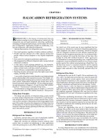
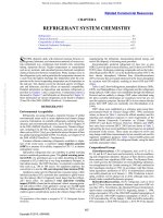
a series of insulated heat exchangers. Figure 1 is a schematic of a
simple system illustrating a single stage of autocascade.
The preparation of this chapter is assigned to TC 10.4, Ultralow-Temperature
Systems and Cryogenics.
Low-Temperature Materials..................................................... 48.6
Insulation ................................................................................. 48.9
Heat Transfer ........................................................................... 48.9
Secondary Coolants ............................................................... 48.10
Fig. 1
Fig. 1 Simple Autocascade Refrigeration System
In this system, two refrigerants with significantly different boiling
points are compressed and circulated by one vapor compressor. Assume that one refrigerant is R-23 (normal boiling point, –82°C) and
the second refrigerant is R-404a (normal boiling point, –46.7°C).
Assume that ambient temperature is 25°C and that the condenser is
100% efficient.
With properly sized components, this system should be able to
achieve –60°C in the absorber while the compression ratio is maintained at 5.1 to 1. As the refrigerant mixture is pumped through the
main condenser and cooled to 25°C at the exit, compressor discharge pressure is maintained at 1524 kPa (gage). At this condition,
virtually all R-404a is condensed at 35°C and then further chilled to
subcooled liquid. Although R-23 molecules are present in both liquid and vapor phases, the R-23 is primarily vapor because of the
large difference in the boiling points of the two refrigerants. A phase
separator at the outlet of the condenser collects the liquid by gravitational effect, and the R-23-rich vapor is removed from the outlet of
the phase separator to the heat exchanger.
At the bottom of the phase separator, an expansion device adiabatically expands the collected R-404a-rich liquid such that the outlet of the device produces a low temperature of –19°C at 220 kPa
(gage) (Weng 1995). This cold stream is immediately sent back to
the heat exchanger in a counterflow pattern to condense the R-23rich vapor to liquid at –18.5°C and 1524 kPa (gage). The R-23-rich
liquid is then adiabatically expanded by a second expansion device
to –60°C. As it absorbs an appropriate amount of heat in the absorber, the R-23 mixes with the expanded R-404a and evaporates in
the heat exchanger, providing a cold source for condensing R-23 on
the high-pressure side of the heat exchanger. Leaving the heat exchanger at superheated conditions, the vapor mixture then returns to
the suction of the compressor for the next cycle.
48.1
Copyright © 2010, ASHRAE
Simple Autocascade Refrigeration System
This file is licensed to Abdual Hadi Nema (). License Date: 6/1/2010
48.2
2010 ASHRAE Handbook—Refrigeration (SI)
Fig. 2
Four-Stage Autocascade System
Licensed for single user. © 2010 ASHRAE, Inc.
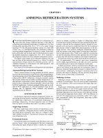
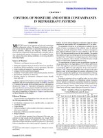
Fig. 2
Four-Stage Autocascade System
As can be seen from this simple example, the autocascade effect
derives from a short cycle of the refrigerant circuit within the system that performs only internal work to condense the lower boiling
point refrigerant.
The concept of the single-stage cycle can be extended to multiple
stages. Figure 2 shows the flow diagram of a four-stage system. The
condensation and subsequent expansion of one refrigerant provides
the cooling necessary to condense the next refrigerant in the heat
exchanger downstream. This process continues until the last refrigerant with the lowest boiling point is expanded to achieve extremely
low temperature.
The design process includes selection of (1) metal for piping and
vessels and (2) insulating material and method of application. The
product to be refrigerated may actually pass through the evaporator,
but in many cases a secondary coolant transfers heat from the final
product to the evaporator. Brines and antifreezes that perform satisfactorily at higher temperatures may not be suitable at low temperatures. Compressors are subjected to unusual demands when
operating at low temperatures, and, because they must be lubricated,
oil selection and handling must be addressed.
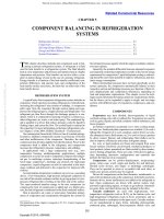
Design Considerations
Single-refrigerant systems are contrasted with the cascade system,
which consists of two separate but thermally connected refrigerant
circuits, each with a different refrigerant (Stoecker and Jones 1982).
In the industrial refrigeration sector, the traditional refrigerants
have been R-22 and ammonia (R-717). Because R-22 will ultimately be phased out, various hydrofluorocarbon (HFC) refrigerants and blends are proposed as replacements. Two that might be
considered are R-507 and R-404a.
Compressor Capacity. As can be seen from Figures 1 and 2, a
significant amount of compressor work is used for internal evaporating and condensing of refrigerants. The final gain of the system is
therefore relatively small. Compressor capacity must be enough to
produce an appropriate amount of final refrigerating effect.
Heat Exchanger Sizing. Because there is a significant amount
of refrigerant vapor in each stage of the heat exchanger, the overall
heat transfer coefficients on both the evaporating and condensing
sides are rather small compared to those of pure components at
phase-changing conditions. Therefore, generous heat-transfer area
should be provided for energy exchange between refrigerants on the
high- and low-pressure sides.
Expansion Devices. Each expansion device is sized to provide
sufficient refrigerating effect for the adjacent downstream heat
exchanger.
Compressor Lubrication. General guidelines for lubrication of
refrigeration systems should be adopted.
CUSTOM-DESIGNED AND FIELDERECTED SYSTEMS
If refrigeration is to maintain a space at a low temperature to store
a modest quantity of product in a chest or cabinet, the packaged lowtemperature system is probably the best choice. Prefabricated walkin environmental chambers are also practical solutions when they
can accommodate space needs. When the required refrigeration
capacity exceeds that of packaged systems, or when a fluid must be
chilled, a custom-engineered system should be considered.
The refrigeration requirement may be to chill a certain flow rate
of a given fluid from one temperature to another. Part of the design
process is to choose the type of system, which may be a multistage
plant using a single refrigerant or a two-circuit cascade system using
a high-pressure refrigerant for the low-temperature circuit. The
compressor(s) and condenser(s) must be selected, and the evaporator and interstage heat exchanger (in the case of the cascade system)
must be either selected or custom-designed.
SINGLE-REFRIGERANT SYSTEMS
Two-Stage Systems
In systems where the evaporator operates below about
–20°C, two-stage or compound systems are widely used. These systems are explained in Chapter 2 of this volume and in Chapter 2 of
the 2009 ASHRAE Handbook—Fundamentals. Advantages of twostage compound systems that become particularly prominent when
the evaporator operates at low temperature include
• Improved energy efficiency because of removal of flash gas at the
intermediate pressure and desuperheating of discharge gas from
the low-stage compressor before it enters the high-stage compressor.
• Improved energy efficiency because two-stage compressors are
more efficient operating against discharge-to-suction pressure
ratios that are lower than for a single-stage compressor.
• Avoidance of high discharge temperatures typical of single-stage
compression. This is important in reciprocating compressors but
of less concern with oil-injected screw compressors.
• Possibility of a lower flow rate of liquid refrigerant to the evaporator because the liquid is at the saturation temperature of the
intermediate pressure rather than the condensing pressure, as is
true of single-stage operation.
Refrigerant and Compressor Selection
The compound, two-stage (or even three-stage) system is an
obvious possibility for low-temperature applications. However, at
very low temperatures, limitations of the refrigerant itself appear:
freezing point, pressure ratios required of the compressors, and
This file is licensed to Abdual Hadi Nema (). License Date: 6/1/2010
Ultralow-Temperature Refrigeration
48.3
Table 1 Low-Temperature Characteristics of Several
Refrigerants at Three Evaporating Temperatures
Pressure Ratio with
Two-Stage System
Refrige Freezing
rant
Point
Licensed for single user. © 2010 ASHRAE, Inc.
R-22
–160°C
R-507
<–100°C
R-717
–77.8°C
R-404a <– 100°C
Evaporating Temp.
–50°C –70°C –90°C
4.6
4.4
5.75
4.36
8.14
7.8
11.1
7.58
17.9
16.1
25.4
15.2
Fig. 3
Simple Cascade System
Volumetric Flow of
Refrigerant, L/s per kW
Evaporating Temp.
–50°C –70°C
–90°C
1.57
1.29
2.05
1.34
19.8
17.5
—
16.75
4.81
4.08
7.24
4.13
volumetric flow at the suction of the low-stage compressor per unit
refrigeration capacity. Table 1 shows some key values for four candidate refrigerants, illustrating some of the concerns that arise when
considering refrigerants that are widely applied in industrial refrigeration systems. Hydrocarbons (HCs), which are candidates particularly in the petroleum and petrochemical industry, where the entire
plant is geared toward working with flammable gases, are not
included in Table 1.
The freezing point is not a limitation for the halocarbon refrigerants, but ammonia freezes at –77.8°C, so its use must be
restricted to temperatures safely above that temperature.
The pressure ratios the compressors must operate against in
two-stage systems are also important. A condensing temperature of
35°C is assumed, with the intermediate pressure being the geometric
mean of the condensing and evaporating pressures. Many lowtemperature systems may be small enough that a reciprocating
compressor would be favorable, but the limiting pressure ratio
with reciprocating compressors is usually about 8, a value chosen
to limit the discharge temperature. An evaporating temperature of
–70°C is about the lowest permissible for systems using reciprocating compressors. For evaporating temperatures lower than –70°C,
consider using a three-stage system. An alternative to the reciprocating compressor is the screw compressor, which operates with lower
discharge temperatures because it is oil flooded. The screw compressor can therefore operate against larger pressure ratios than the
reciprocating compressor, and is favored in larger systems.
The required volumetric pumping capacity of the compressor
is measured at the compressor suction. This value is an indicator of
the physical size of the compressor; the values become huge at the
–90°C evaporating temperature.
Some conclusions from Table 1 are
• A single-refrigerant, two-stage system can adequately serve a
plant in the higher-temperature portion of the range considered
here, but it becomes impractical in the lower-temperature portion.
• Ammonia, which has many favorable properties for industrial
refrigeration, has little appeal for low-temperature refrigeration
because of its relatively high freezing point and pressure ratios.
Special Multistage Systems
Special high-efficiency operations to recover volatile compounds such as hydrocarbons use the reverse Brayton cycle. This
consists of one or two conventional compressor refrigeration cycles
with the lowest stage ranging from –60 to –100°C. This final stage
is achieved by using a turbo compressor/expander and enables the
collection of liquefied hydrocarbons (Emhö 1997; Enneking and
Priebe 1993; Jain and Enneking 1995).
CASCADE SYSTEMS
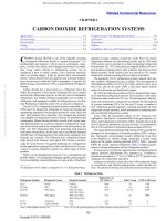
The cascade system (Figure 3) confronts some of the problems of
single-refrigerant systems. It consists of two separate circuits, each
using a refrigerant appropriate for its temperature range. The two
circuits are thermally connected by the cascade condenser, which is
the condenser of the low-temperature circuit and the evaporator of
Fig. 3 Simple Cascade System
Fig. 4
Simple Cascade Pressure-Enthalpy Diagram
Fig. 4
Simple Cascade Pressure-Enthalpy Diagram
the high-temperature circuit. Typical refrigerants for the hightemperature circuit include R-22, ammonia, R-507, and R-404a. For
the low-temperature circuit, a high-pressure refrigerant with a high
vapor density (even at low temperatures) is chosen. For many years,
R-503, an azeotropic mixture of R-13 and R-23, was a popular
choice, but R-503 is no longer available because R-13 is an ozonedepleting chlorofluorocarbon (CFC). R-23 could be and has been
used alone, but R-508b, an azeotrope of R-23 and R-116, has superior properties, as discussed in the section on Refrigerants for LowTemperature Circuit.
The cascade system has some of the thermal advantages of twostage, single-refrigerant systems: it approximates flash gas removal
and allows each compressor to take a share of the total pressure ratio
between the low-temperature evaporator and the condenser. The cascade system has the thermal disadvantage of needing to provide an
additional temperature lift in the cascade condenser because the condensing temperature of the low-temperature refrigerant is higher
than the evaporating temperature of the high-temperature refrigerant.
There is an optimum operating temperature of the cascade condenser
for minimum total power requirement, just as there is an optimum
intermediate pressure in two-stage, single-refrigerant systems.
Figure 3 shows a fade-out vessel, which limits pressure in the lowtemperature circuit when the system shuts down. At room temperature, the pressure of R-23 or R-508b in the system would exceed
4000 kPa if liquid were present. The entire low-temperature system
must be able to accommodate this pressure. The process occurring
in the fade-out vessel is at constant volume, as shown on the
This file is licensed to Abdual Hadi Nema (). License Date: 6/1/2010
48.4
2010 ASHRAE Handbook—Refrigeration (SI)
pressure-enthalpy diagram of Figure 4. When the system operates
at low temperature, the refrigerant in the system is a mixture of
liquid and vapor, indicated by point A. When the system shuts
down, the refrigerant begins to warm and follows the constantvolume line, with pressure increasing according to the saturation
curve. When the saturated vapor line is reached at point B, further
increases in temperature result in only slight increases in pressure
because the refrigerant is superheated vapor.
Larger cascade systems are field engineered, but packaged systems are also available. Figure 5 shows a two-stage system with the
necessary auxiliary equipment. Figure 6 shows a three-stage cascade system.
Licensed for single user. © 2010 ASHRAE, Inc.
Fig. 5 Two-Stage Cascade System
Fig. 5
Two-Stage Cascade System
Fig. 6 Three-Stage Cascade System
Fig. 6 Three-Stage Cascade System
This file is licensed to Abdual Hadi Nema (). License Date: 6/1/2010
Ultralow-Temperature Refrigeration
48.5
Refrigerants for Low-Temperature Circuit
R-503 is no longer available for general use. R-23 can be used,
but R-508b, an azeotropic mixture of non-ozone-depleting R-23 and
R-116, is superior. It is nonflammable and has zero ozone depletion
potential (ODP). Table 2 lists some properties of R-508b.
R-508b offers excellent operating characteristics compared to
R-503 and R-13. Capacity and efficiency values are nearly equivalent
to R-503’s and superior to R-13’s. The compressor discharge temperature is lower than for R-23; lower discharge temperatures may
equate to longer compressor life and better lubricant stability. The
estimated operating values of a cascade system running with
R-508b are shown in Table 3. Performance parameters of R-503,
R-13, and R-23 are shown for comparison.
Table 4 shows calculated data for R-23 and R-508b for two
operating ranges. The volumetric efficiency is 100%. Actual compressor performance varies with pressure ratios and yields lower capacity and efficiencies and higher discharge temperatures and flow
requirements than shown.
Licensed for single user. © 2010 ASHRAE, Inc.
Compressor Lubrication
When selecting a lubricant to use with R-508b in an existing lowtemperature system, consider (1) refrigerant/lubricant miscibility,
(2) chemical stability, (3) materials compatibility, and (4) refrigeration system design. Original equipment manufacturers and compressor suppliers should be consulted.
Table 2 Properties of R-508b
Boiling point (101.325 kPa)
Critical temperature
Critical pressure
Latent heat of vaporization at boiling point
Ozone depletion potential (R-12 = 1)
Flammability
Exposure limit (8 and 12 h)*
–88°C
13.7°C
3935 kPa
168.4 kJ/kg
0
Nonflammable
1000 ppm
*The exposure limit is a calculated limit determined from the DuPont airborne exposure limit (AEL) of the individual components. The AEL is the maximum amount to
which nearly all workers can be repeatedly exposed during a working lifetime without
adverse effects.
Table 3
Theoretical Performance of Cascade System Using
R-13, R-503, R-23, or R-508b
Capacity (R-503 = 100)
Efficiency (R-503 = 100)
Discharge pressure, kPa
Suction pressure, kPa
Discharge temperature, °C
R-503
R-13
R-23
R-508b
100
100
999
110
107
71
105
717
83
92
74
95
848
90
138
98
103
1013
10
87
Note: Operating conditions are –84.4°C evaporator, –35°C condenser; 5.6 K subcooling; –17.8°C suction temperature; 70% isentropic compression efficiency, 4% volumetric clearance.
Table 4
Theoretical Compressor Performance Data for
Two Different Evaporating Temperatures
Evaporating
Temperature,
°C
Refrigerant
–80
–100
Pressure
Ratio
Discharge
Temperature,
°C
Volumetric
Flow,
L/s per kW
R-23
7.49
58
1.10
R-508b
6.51
32
0.866
R-23
26.88
72
3.85
R-508b
21.88
39
2.94
Basis: –35°C condensing temperature; compressor efficiency of 70%; volumetric efficiency of 100%; 10 K subcooling, and 50 K suction superheat.
Using additives to enhance system performance is well established in the low-temperature industry, and may be applied to
R-508b. The miscibility of R-508b with certain polyol esters
(POEs) is slightly better than the limited miscibility of R-13 and
R-503 with mineral oil and alkylbenzene, which helps oil circulation at the low evaporator temperatures. Even with increased miscibility, additives may enhance performance. Some POE oils
designed for use in very-low-temperature systems have been used
successfully with R-508b in equipment retrofits. Consult compressor manufacturers and suppliers before a final decision on lubricants
and any additives.
Compressors
Larger cascade systems typically use standard, positivedisplacement compressors in the dual refrigeration system. The
evaporator of the higher-temperature refrigerant system serves as
the condenser for the lower-temperature one. This allows rather normal application of the compressors on both systems in relation to the
pressures, compression ratios, and oil and discharge temperatures
within the compressors. However, several very important items
must be considered for both the high and low sides of the cascade
system to avoid operational problems. Commercially available
compressors must be analyzed for both sides of the cascade to determine the best combination for a suitable intermediate high-side
evaporator/low-side condenser and minimum (or economical) system power usage.
High-Temperature Circuit. The higher-temperature system is
generally a single- or two-stage system using a commercial refrigerant (R-134a, R-22, R-404a, or R-717); evaporating temperature is
approximately –23 to –45°C, and condensing is at normal ambient
conditions. Commercially available reciprocating and screw compressors are suitable. If compressor evaporating temperature is below –45°C, a suction-line heat exchanger is needed to superheat
compressor suction gas to at least –43°C to avoid the metal brittleness associated with lower temperatures at the compressor suction valve and body. Suction piping materials and the evaporator/
condenser (evaporator side) must also be suitable for these low temperatures per American Society of Mechanical Engineers (ASME)
code requirements.
Lubricant for the higher-temperature system must be compatible
with the refrigerant and suitable for the type of system, considering oil carryover and return from the evaporator and the lowtemperature conditions within the evaporator.
Low-Temperature Circuit. The compressor may also be a standard refrigeration compressor, if the compressor suction gas is superheated to at least –43°C to avoid low-temperature metal brittleness.
Operation is typically well within standard pressure, oil temperature,
and discharge temperature limits. The refrigerant is usually R-23 or
R-508b. Because temperatures in the low side are below –45°C, all
piping, valves, and vessels must be of materials that comply with
ASME codes for these temperatures.
It may be difficult to obtain compressor rating data for lowtemperature applications with these refrigerants because few
actual test data are available, and the manufacturer may be reluctant to be specific. Therefore, the low side should not be designed
too close to the required specification. Good practice is to calculate the actual volumetric flow rate to be handled by the compressor (at the expected superheat) to be certain that it can perform as
required.
Capacity loss from high superheat is more than recouped (for a
net capacity gain) from the liquid subcooling obtained by the suction-line heat exchanger. In rare cases, it may be necessary to inject
a small quantity of hot gas into the suction to ensure maximum suction temperature.
The lubricant selected for the low side must be compatible with
the specific refrigerant used and also suitable for the low temperatures expected in the evaporator. It is important that adequate
This file is licensed to Abdual Hadi Nema (). License Date: 6/1/2010
48.6
2010 ASHRAE Handbook—Refrigeration (SI)
coalescing oil separation (5 ppm) is provided to minimize oil carryover from compressor to evaporator.
In direct-expansion evaporators, any oil is forced through the
tubes, but speed in the return lines must be high enough to keep
this small amount of oil moving back to the compressor. If the system has capacity control, then multiple suction risers or alternative
design procedures may be required to prevent oil logging in the
evaporator and ensure oil return. At these ultralow temperatures, it
is imperative to select a lubricant that remains fluid and does not
plate out on the evaporator surfaces, where it can foul heat transfer.
Choice of Metal for Piping and Vessels
Licensed for single user. © 2010 ASHRAE, Inc.
The usual construction metal for use with thermal fluids is
carbon steel. However, carbon steel should not be used below –29°C
because of its loss of ductility. Consider using 304 or 316 stainless
steel because of their good low-temperature ductility. Another alternative is to use carbon steel that has been manufactured specifically
to retain good ductility at low temperatures (Dow Corning USA
1993). For example,
Carbon steel
SA - 333 - GR1
SA - 333 - GR7
SA - 333 - GR3
SA - 333 - GR6
Down to –29°C
–29 to –46°C
–46 to –73°C
–59 to –101°C
To –46°C
LOW-TEMPERATURE MATERIALS
Choosing material for a specific low-temperature use is often a
compromise involving several factors:
•
•
•
•
•
•
•
Cost
Stress level at which the product will operate
Manufacturing alternatives
Operating temperature
Ability to weld and stress-relieve welded joints
Possibility of excessive moisture and corrosion
Thermal expansion and modulus of elasticity characteristics for
bolting and connection of dissimilar materials
• Thermal conductivity and resistance to thermal shock
Effect of Low Temperature on Materials. When the piping and
vessels are to contain refrigerant at low temperature, special materials must usually be chosen because of the effect of low temperature on material properties. Chemical interactions between the
refrigerant and containment material must also be considered.
Mechanical and physical properties, fabricability, and availability
are some of the important factors to consider. Few generalizations
can be made, except that decreased temperature increases hardness,
strength, and modulus of elasticity. The effect of low temperatures
on ductility and toughness can vary considerably between materials.
With a decrease in temperature, some metals show increased ductility; others increase at some limiting low temperature, followed by a
decrease at lower temperatures. Still other metals decrease in toughness and ductility as temperature decreases below room temperature.
The effect of temperature reduction on polymers depends on the
type of polymer. Thermoplastic polymers, which soften when
heated above their glass transition temperature Tg, become progressively stiffer and finally brittle at low temperatures. Thermosetting
plastics, which are highly cross-linked and do not soften when
heated, are brittle at both ambient and lower temperatures. Elastomers (rubbers) are lightly cross-linked and stiffen like thermoplastics as the temperature is lowered, becoming fully brittle at very low
temperatures.
Although polymers become brittle and may crack at low temperatures, their unique combination of properties (excellent thermal
and electrical insulation capability, low density, low heat capacity,
and nonmagnetic character) make them attractive for a variety of
lower-temperature applications. At extremely low temperatures, all
plastic materials are very brittle and have low thermal conductivity
and low strength relative to metals and composites, so selection and
use must be carefully evaluated.
Fiber composite materials have gained widespread use at low
temperatures, despite their incorporation of components that are
often by themselves brittle. A factor that must be considered in the
use of composites is the possibility of anisotropic behavior, in
which they exhibit properties with different values when measured
along axes in different directions. Composites with aligned fibers
are highly anisotropic.
Metals
The relation of tensile strength to temperature for common structural metals at low temperatures is shown in Figure 7 (Askeland
1994). The slopes of the curves indicate that the increase in strength
with decrease in temperature varies. However, tensile strength is not
the best criterion for determining the suitability of a material for
low-temperature service, because most failures result from a loss of
ductility.
Lower temperatures can have a dramatic effect on the ductility
of metal; the effect depends to a large extent on crystal structure.
Metals and alloys that are face-centered cubic (FCC) and ductile at
ambient temperatures remain ductile at low temperatures; this category includes aluminum, copper, copper-nickel alloys, nickel, and
austenitic stainless steels. Metals and alloys that are body-centered
cubic (BCC), such as pure iron, carbon steel, and many alloy steels,
become brittle at low temperatures. Many BCC metals and alloys
exhibit a ductile-to-brittle transition at lower temperatures (see 1020
steel in Figure 8). This loss of ductility comes from a decrease in the
Fig. 7 Tensile Strength Versus Temperature of
Several Metals
Fig. 7 Tensile Strength Versus Temperature of
Several Metals
Fig. 8 Tensile Elongation Versus Temperature of
Several Metals
Fig. 8
Tensile Elongation Versus Temperature of
Several Metals
This file is licensed to Abdual Hadi Nema (). License Date: 6/1/2010
Ultralow-Temperature Refrigeration
48.7
Table 5 Several Mechanical Properties of Aluminum Alloys at –196°C
Aluminum Alloy
Licensed for single user. © 2010 ASHRAE, Inc.
1100-0
2219-T851
5083-0
6061-T651
Modulus of Elasticity,
GPa
78
85
80
77
Yield Strength,
MPa
Ultimate Tensile
Strength, GPa
Percent Elongation
at Failure, %
Plane Strain Fracture Toughness,
MPa ·m1/2
190
568
434
402
—
14
32
23
—
45
62
42
50
440
158
337
number of operating slip systems, which accommodate dislocation
motion. Hexagonal close-packed (HCP) metals and alloys occupy
an intermediate place between FCC and BCC materials and may
remain ductile or become brittle at low temperatures. Zinc becomes brittle, whereas pure titanium (Ti) and many Ti alloys
remain ductile.
Ductility values obtained from the static tensile test may give
some clue to ductility loss, but the notched-bar impact test gives a
better indication of how the material performs under dynamic loading and how it reacts to complex multidirectional stress. Figure 8
shows ductility, as measured by percent elongation in the tensile
test, in relation to temperature for several metals. As temperature
drops, the curves for copper and aluminum show an increase in
ductility, while AISI 304 stainless steel and Ti-6%Al-4%V show a
decrease.
Aluminum alloys are used extensively for low-temperature
structural applications because of cost, weldability, and toughness.
Although their strength is considered modest to intermediate, they
remain ductile at lower temperatures. Typical mechanical properties at –196°C are listed in Table 5. Property values between ambient (21°C) and –196°C are intermediate between those at these
temperatures.
Aluminum 1100 (relatively pure at 99% Al) has a low yield
strength but is highly ductile and has a high thermal conductivity. It
is used in nonstructural applications such as thermal radiation
shields. For structural purposes, alloys 5083, 5086, 5454, and 5456
are often used. Alloys such as 5083 have a comparatively high
strength when annealed (0) and can be readily welded with little loss
of strength in the heat-affected zone; post-welding heat treatments
are not necessary. These alloys are used in the storage and transportation areas. Alloy 3003 is widely used for plate-fin heat exchangers
because it is easily brazed with an Al-7%Si filler metal. Aluminummagnesium alloys (6000 series) are used as extrusions and forgings
for such components as pipes, tubes, fittings, and valve bodies.
Copper alloys are rarely used for structural applications because
of joining difficulties. Copper and its alloys behave similarly to aluminum alloys as temperature decreases. Strength is typically inversely proportional to impact resistance; high-strength alloys have
low impact resistance. Silver soldering and vacuum brazing are the
most successful methods for joining copper. Brass is useful for
small components and is easily machined.
Nickel and nickel alloys do not exhibit a ductile-to-brittle transition as temperature decreases and can be welded successfully, but
their high cost limits use. High-strength alloys can be used at very
low temperatures.
Iron-based alloys that are body-centered cubic usually exhibit a
ductile-to-brittle transition as the temperature decreases. The BCC
phase of iron is ferromagnetic and easily identified because it is
attracted to a magnet. Extreme brittleness is often observed at lower
temperatures. Thus, BCC metals and alloys are not normally used
for structural applications at lower temperatures. Notable exceptions are iron alloys with a high nickel content.
Nickel and manganese are added to iron to stabilize the austenitic
phase (FCC), promoting low-temperature ductility. Depending on
the amount of Ni or Mn added, a great deal of low-temperature
toughness can be developed. Two notable high-nickel alloys for use
below ambient temperature include 9% nickel steel and austenitic
36% Ni iron alloy. The 9% alloy retains good ductility down to
100 K (–173°C). Below 100 K, ductility decreases slightly, but a
clear ductile-to-brittle transition does not occur. Iron containing
36% Ni has the unusual feature of nearly zero thermal contraction
during cooling from room temperature to near absolute zero. It is
therefore an attractive metal for subambient use where the thermal
stress associated with differential thermal contraction is to be
avoided. Unfortunately, this alloy is quite expensive and therefore
sees limited use.
Lesser amounts of Ni can be added to Fe to lower cost and depress
the ductile-to-brittle transition temperature. Iron with 5% Ni can be
used down to 150 K (–123°C), and Fe with 3.5% Ni remains ductile
to 170 K (–102°C). High-nickel steels are usually heat treated before
use by water quenching from 800°C, followed by tempering at
580°C. The 580°C heat treatment tempers martensite formed during
quenching and produces 10 to 15% stable austenite, which is responsible for the improved toughness of the product.
The austenitic stainless steels (300 series) are widely used for
low-temperature applications. Many retain high ductility down to
4 K (–269°C) and below. Their attractiveness is based on good
strength, stiffness, toughness, and corrosion resistance, but cost is
high compared to that of Fe-C alloys. A stress relief heat treatment
is generally not required after welding, and impact strengths vary
only slightly with decreasing temperature. A popular, readily available steel with moderate strength for low-temperature service is
AISI type 304, with the low-carbon grade preferred. Where higher
strengths are needed and welding can be avoided, strain-hardened or
high-nitrogen grades are available. Castable austenitic steels are
also available; a well-known example (14-17%Cr, 18-22%Ni, 1.752.75%Mo, 0.5%Si max, and 0.05%C max) retains excellent ductility and strength to extremely low temperatures.
Titanium alloys have high strength, low density, and poor thermal
conductivity. Two alloys often used at low temperatures are Ti-5%Al2.5%Sn and Ti-6%Al-4%V. The Ti-6-4 alloy has the higher yield
strength, but loses ductility below about 80 K (–193°C). The lowtemperature properties are dramatically affected by oxygen, carbon,
and nitrogen content. Higher levels of these interstitial elements
increase strength but decrease ductility. Extra-low interstitial (ELI)
grades containing about half the normal levels are usually specified
for low-temperature applications. Both Ti-6-4 and Ti-5-2.5 are easily welded but expensive and difficult to form. They are used where
a high strength-to-mass or strength-to-thermal conductivity ratio is
attractive. Titanium alloys are not recommended for applications
where an oxidation hazard exists.
Thermoplastic Polymers
Reducing the temperature of thermoplastic polymers restricts
molecular motion (bond rotations and molecules sliding past one
another), so that the material becomes less deformable. Behavior
normally changes rapidly over a narrow temperature range, beginning at the material’s glass transition temperature Tg.
Figure 9 shows the general mechanical response of linear amorphous thermoplastics to temperature. At or above the melting temperature Tm, bonding between polymer chains is weak, the material
flows easily, and the modulus of elasticity is nearly zero. Just below
Tm, the polymer becomes rubbery; with applied stress, the material
deforms by elastic and plastic strain. The combination of these
deformations is related to the applied stress by the shear modulus. At
still lower temperatures, the polymer becomes stiffer, exhibiting
This file is licensed to Abdual Hadi Nema (). License Date: 6/1/2010
48.8
2010 ASHRAE Handbook—Refrigeration (SI)
Fig. 9 Shear Modulus Versus Normalized Temperature (T/
Tg) for Thermoplastic Polymers
Fig. 10 Tensile Strength Versus Temperature of Plastics and
Polymer Matrix Laminates
Fig. 10 Tensile Strength Versus Temperature of
Plastics and Polymer Matrix Laminates
Licensed for single user. © 2010 ASHRAE, Inc.
Fig. 9 Shear Modulus Versus Normalized Temperature
(T/Tg) for Thermoplastic Polymers
Table 6 Approximate Melting and Glass Transition
Temperatures for Common Polymers
Melting
Temperature Tm
Polymer
Addition polymers
Low-density polyethylene
High-density polyethylene
Polyvinyl chloride
Polypropylene
Polystyrene
Polytetrafluoroethylene
Polymethyl methacrylate
(acrylic)
Condensation polymers
6-6 Nylon
Polycarbonate
Polyester
Elastomers
Silicone
Polybutadiene
Polychloroprene
Polyisoprene
Tg
K
°C
K
°C
390
415
—
445
—
605
—
115
140
—
170
—
330
—
155
155
365
260
380
—
370
–120
–120
90
–15
105
—
95
540
—
530
265
—
255
320
420
350
50
145
75
—
395
355
305
—
115
80
30
150
185
220
200
–125
–90
–50
–70
Source: Askeland (1994). Derived from Table 15-2, p. 482.
“leathery” behavior and a higher stress at failure. Many commercially available polymers (e.g., polyethylene) are used in this condition. Tg is at the transition between the leathery and glassy regions,
and is usually 0.5 to 0.75 times the absolute melting temperature Tm.
Table 6 lists Tg and Tm values for common polymers. In the glassy
state, at temperatures below Tg, the polymer is hard, brittle, and
glass-like. Although polymers in the glassy region have poor ductility and formability, they are strong, stiff, and creep-resistant.
For thermoplastic polymers, the temperature at which stress is
applied and the rate of stress application are interdependent based
on time/temperature superposition. This relationship allows different types of tests, such as creep or stress relaxation, to be related
through a single curve that describes the viscoelastic response of the
material to time and temperature. Applying stress more rapidly has
an effect equivalent to applying stress at lower temperatures. Figure
10 shows tensile strength versus temperature for plastic and polymer composites.
Thermoplastic polymers such as polyethylene and polyvinyl chloride (PVC) may be used for plastic films and wire insulation but
are not generally suitable for structural applications because of their
brittleness at temperatures below Tg. The only known polymer that
exhibits appreciable ductility at temperatures substantially below Tg
is polytetrafluoroethylene (PTFE). Because of their large thermal
contraction coefficients, thermoplastic polymers should not be restrained during cooldown. Large masses should be cooled slowly to
ensure uniform thermal contraction; the coefficient of thermal contraction decreases with temperature. Contractions of 1 to 2% in cooling from ambient to –196°C are common. For instance, nylon, PTFE,
and polyethylene contract 1.3, 1.9, and 2.3%, respectively. These values are large compared to those for metals, which contract 0.2 to 0.3%
over the same temperature range.
Thermosetting Plastics
Thermosetting plastics such as epoxy are relatively unaffected
by changes in temperature. As a class, they are brittle and generally used in compression and not tension. Care must be taken in
changing their temperature to avoid thermally induced stress,
which could lead to cracking. Adding particulate fillers such as silica (SiO2) to thermosetting resins can increase elastic modulus and
decrease strength. The main reasons for adding fillers are to reduce
the coefficient of thermal expansion and to improve thermal conductivity. Filled thermosetting resins such as epoxy and polyester
can be made to have coefficients of thermal expansion that closely
match those of metal; they may be used as insulation and spacers
but are not generally used for load-bearing structural applications.
Fiber Composites
Nonmetallic filamentary reinforced composites have gained
wide acceptance for low-temperature structural applications because they have good strength, low density, and low thermal conductivity. Nonmetallic insulating composites are usually formed
by laminating together layers of fibrous materials in a liquid thermosetting resin such as polyester or epoxy. The fibers are often but
not necessarily continuous; they can take the form of bundles,
mats, yarns, or woven fabrics. The most frequently used fiber materials include glass, aramid, and carbon. Reinforcing fibers add
considerable mechanical strength to otherwise brittle matrix material and can lower the thermal expansion coefficient to a value
comparable to that of metals. High figures of merit (ratio of thermal conductivity to elastic modulus or strength) can reduce refrigeration costs substantially from those obtained with fully metallic
configurations. Nonmetallic composites can be used for tanks,
tubes, struts, straps, and overlays in low-temperature refrigeration
systems. These materials perform well in high-loading environments and under cyclic stress; they do not degrade chemically at
low temperatures.
This file is licensed to Abdual Hadi Nema (). License Date: 6/1/2010
Ultralow-Temperature Refrigeration
48.9
Table 7 Tensile Properties of Unidirectional
Fiber-Reinforced Composites
Composite
Test Temperature, Tensile Strength, Tensile Modulus,
°C
MPa
GPa
E glass (50%)
Longitudinal
Transverse
Aramid fibers (63%)
Longitudinal
Transverse
Table 8 Components of a Low-Temperature Refrigerated Pipe
Insulation System
22
–196
22
–196
1050
1340
9
8
41
45
11
12
22
–196
22
–196
1130
1150
4.2
3.6
71
99
2.5
3.6
Insulation
System
Component
Insulation
Licensed for single user. © 2010 ASHRAE, Inc.
Source: Hands (1986). Table 11.3.
Different combinations of fiber materials, matrices, loading fractions, and orientations yield a range of properties. Material properties are often anisotropic, with maximum properties in the fiber
direction. Composites fail because of cracking in the matrix layer
perpendicular to the direction of stress. Cracking may propagate
along the fibers but does not generally lead to debonding. Maximum
elongations at failure for glass-reinforced composites are usually 2
to 5%; the material is generally elastic all the way to failure.
A major advantage of using glass fibers with a thermosetting
binder matrix is the ability to match thermal contraction of the
composite to that of most metals. Aramid fibers produce laminates with lower density but higher cost. With carbon fibers, it is
possible to produce components that show virtually zero contraction on cooling.
Typical tensile mechanical property data for glass-reinforced
laminates are given in Table 7. Under compressive loading, strength
and modulus values are generally 60 to 70% of those for tensile
loading because of matrix shrinkage away from fibers and microbuckling of fibers.
Adhesives
Adhesives for bonding composite materials to themselves or to
other materials include epoxy resins, polyurethanes, polyimides,
and polyheterocyclic resins. Epoxy resins, modified epoxy resins
(with nylon or polyamide), and polyurethanes apparently give the
best overall low-temperature performance. The joint must be properly designed to account for the different thermal contractions of the
components. It is best to have adhesives operate under compressive
loads. Before bonding, surfaces to be joined should be free of contamination, have uniform fine-scale roughness, and preferably be
chemically cleaned and etched. An even bond gap thickness of 0.1
to 0.2 mm is usually best.
INSULATION
Refrigerated pipe insulation, by necessity, has become an engineered element of the refrigeration system. The complexity and cost
of this element now rival that of the piping system, particularly for
ultralow-temperature systems.
Some factory-assembled, close-coupled systems that operate
intermittently can function with a relatively simple installation of
flexible sponge/foam rubber pipe insulation. Larger systems that
operate continuously require much more investment in design and
installation. Higher-technology materials and techniques, which are
sometimes waived (at risk of invested capital) for systems operating
at warmer temperatures, are critical for low-temperature operation.
Also, the nature of the application does not usually allow shutdown
for repair.
Pipe insulation systems are distinctly different from cold-room
construction. Cold-room construction vapor leaks can be neutral if
they reach equilibrium with the dehumidification effect of the
Primary Roles
Secondary Roles Typical Materials
Efficiently insulate Limit water
Polyurethanepipe
movement toward modified
pipe
polyisocyanurate
Provide external
foams
hanger support Reduce rate of
moisture/vapor Extruded
transfer toward
polystyrene foams
pipe
Cellular glass
Protect vapor
retarder from
external damage
Elastomeric Limit liquid water
joint
movement
sealant
through
insulation cracks
Reduce rate of
moisture/vapor
transfer toward
pipe
Synthetic rubbers
Resins
Vapor
retarder
Severely limit
moisture transfer
toward pipe
Eliminate liquid
water movement
toward pipe
Mastic/fabric/mastic
Laminated
membranes
and very-lowpermeance plastic
films
Protective
jacket
Protect vapor
Reduce moisture/ Aluminum
retarder from
vapor transfer
Stainless steel
external damage
toward pipe
PVC
Limit water
movement toward
pipe
Protective
Prevent liquid
Limit rate of
jacket joint water movement moisture/vapor
sealant
through gaps in
transfer toward
protective jacket
pipe
Vapor stops
Isolate damage
caused by
moisture
penetration
Mastic/fabric/
mastic
refrigeration unit. Moisture entering the pipe insulation can only
accumulate and form ice, destroying the insulation system. At these
low temperatures, it is proper to have redundant vapor retarders
(e.g., reinforced mastic plus membrane plus sealed jacket). Insulation should be multilayer to allow expansion and contraction, with
inner plies allowed to slide and the outer ply joint sealed. Sealants
are placed in the warmest location because they may not function
properly at the lower temperature of inner plies. Insulation should
be thick enough to prevent condensation (above dew point) at the
outside surface.
The main components of a low-temperature refrigerated pipe
insulation system are shown in Table 8. See Chapter 10 for more
information on insulation systems for refrigerant piping.
HEAT TRANSFER
The heat transfer coefficients of boiling and condensing refrigerant and the convection heat transfer coefficients of secondary coolants
are the most critical heat transfer issues in low-temperature refrigeration. In a cascade system, for example, the heat transfer coefficients
in the high-temperature circuit are typical of other refrigeration applications at those temperatures. In the low-temperature circuit,
however, the lower temperatures appreciably alter the refrigerant
properties and therefore the boiling and condensing coefficients.
This file is licensed to Abdual Hadi Nema (). License Date: 6/1/2010
48.10
The expected changes in properties with a decrease in temperature are as follows. As temperature drops,
Licensed for single user. © 2010 ASHRAE, Inc.
•
•
•
•
•
•
•
•
•
Density of liquid increases
Specific volume of vapor increases
Enthalpy of evaporation increases
Specific heat of liquid decreases
Specific heat of vapor decreases
Viscosity of liquid increases
Viscosity of vapor decreases
Thermal conductivity of liquid increases
Thermal conductivity of vapor decreases
In general, increases in liquid density, enthalpy of evaporation,
specific heats of liquid and vapor, and thermal conductivity of liquid and vapor cause an increase in the boiling and condensing
heat transfer coefficients. Increases in specific volume of vapor
and viscosities of liquid and vapor decrease these heat transfer
coefficients.
Data from laboratory tests or even field observations are scarce
for low-temperature heat transfer coefficients. However, heat transfer principles indicate that, in most cases, lowering the temperature
level at which heat transfer occurs reduces the coefficient. The lowtemperature circuit in a custom-engineered cascade system encounters lower-temperature boiling and condensation than are typical of
industrial refrigeration. In some installations, refrigerant boiling is
within the tubes; in others, it is outside the tubes. Similarly, the
designer must decide whether condensation at the cascade condenser occurs inside or outside the tubes.
Some relative values based on correlations in Chapter 5 of the
2009 ASHRAE Handbook—Fundamentals may help the designer
determine which situations call for conservative sizing of heat
exchangers. The values in the following subsections are based on
changes in properties of R-22 because data for this refrigerant are
available down to very low temperatures. Other halocarbon refrigerants used in the low-temperature circuit of the cascade system are
likely to behave similarly. Predictions are complicated by the fact
that, in a process inside tubes, the coefficient changes constantly as
the refrigerant passes through the circuit. For both boiling and condensing, temperature has a more moderate effect when the process
occurs outside the tubes than when it occurs inside the tubes.
A critical factor in the correlations for boiling or condensing
inside the tubes is the mass velocity G in g/(s·m2). The relative
values given in the following subsections are based on keeping G
in the tubes constant. The result is that G drops significantly
because the specific volume of vapor experiences the greatest
relative change of all the properties. As the vapor becomes less
dense, the linear velocity can be increased and still maintain a
tolerable pressure drop of the refrigerant through the tubes. So G
would not drop to the extent used in the comparison below, and
the reductions shown for tube-side boiling and condensing would
not be as severe as shown.
Condensation Outside Tubes. Based on Nusselt’s film condensation theory, the condensing coefficient at 20°C, a temperature that
could be encountered in a cascade condenser, would actually be
17% higher than the condensing coefficient in a typical condenser at
30°C because of higher latent heat, liquid density, and thermal conductivity. The penalizing influence of the increase in specific volume of vapor is not present because this term does not appear in the
Nusselt equation.
Condensation Inside Tubes. Using the correlation of Ackers
and Rosson (Table 3, Chapter 4 of the 2001 ASHRAE Handbook—
Fundamentals) with a constant velocity and thus decreasing the
value of G by one-fifth, the condensation coefficient at 20°C is onefourth that at 30°C.
Boiling Inside Tubes. Using the correlation of Pierre [Equation
(1) in Table 2, Chapter 4 of the 2001 ASHRAE Handbook—Fundamentals] and maintaining a constant velocity, when the temperature
2010 ASHRAE Handbook—Refrigeration (SI)
drops to 70°C, the boiling coefficient drops to 46% of the value at
20°C.
Boiling Outside Tubes. In a flooded evaporator with refrigerant
boiling outside the tubes, the heat-transfer coefficient also drops as
the temperature drops. Once again, the high specific volume of
vapor is a major factor, restricting the ability of liquid to be in contact with the tube, which is essential for good boiling. Figure 4 in
Chapter 5 (Perry 1950; Stephan 1963a, 1963b, 1963c) of the 2009
ASHRAE Handbook—Fundamentals shows that the heat flux has a
dominant influence on the coefficient. For the range of temperatures
presented for R-22, the boiling coefficient drops by 12% as the boiling temperature drops from –15°C to –41°C.
SECONDARY COOLANTS
Secondary coolant selection, system design considerations, and
applications are discussed in Chapter 13; properties of brines, inhibited glycols, halocarbons, and nonaqueous fluids are given in Chapter 31 of the 2009 ASHRAE Handbook—Fundamentals. The focus
here is on secondary coolants for low-temperature applications in
the range of –50 to –100°C.
An ideal secondary coolant should
• Have favorable thermophysical properties (high specific heat, low
viscosity, high density, and high thermal conductivity)
• Be nonflammable, nontoxic, environmentally acceptable, stable,
noncorrosive, and compatible with most engineering materials
• Possess a low vapor pressure
Only a few fluids meet these criteria, especially in the entire –50 to
–100°C range. Some of these fluids are hydrofluoroether (HFE),
diethylbenzene, d-limonene, polydimethylsiloxane, trichloroethylene, and methylene chloride. Table 9 provides an overview of these
coolants. Table 10 gives refrigerant properties for the coolants at
various low temperatures.
Polydimethylsiloxane, known as silicone oil, is environmentally
friendly, nontoxic, and combustible and can operate in the whole
range. Because of its high viscosity (greater than 10 mPa·s), its flow
pattern is laminar at lower temperatures, which limits heat transfer.
d-Limonene is optically active terpene (C10H16) extracted from
orange and lemon oils. This fluid can be corrosive and is not recommended for contact with some important materials (polyethylene,
polypropylene, natural rubber, neoprene, nitrile, silicone, and PVC).
Some problems with stability, such as increased viscosity with time,
are also reported. Contact with oxidizing agents should be avoided.
The values listed are based on data provided by the manufacturer in
a limited temperature range. d-Limonene is a combustible liquid
with a flash point of 46.1°C.
The synthetic aromatic heat transfer fluid group includes diethylbenzene. Different proprietary versions of this coolant contain
Table 9 Overview of Some Secondary Coolants
Flash
Point,
°C
Freezing
Point,
°C
Boiling
Point,
°C
Temperature at
Which Viscosity
> 10 mm2/s
Polydimethylsiloxane
46.7
–111.1
175
–60
d-Limonene
46.1
96.7
154.4
–80
58
<–84
181
–80
Coolant
Diethylbenzene*
–75
181
–70
Hydrofluoroether not flamm.
58
–130
60
–30
Ethanol
12
–117
78
–60
Methanol
11
–98
64
–90
*Two proprietary versions containing different additives.
This file is licensed to Abdual Hadi Nema (). License Date: 6/1/2010
Ultralow-Temperature Refrigeration
Table 10
48.11
Refrigerant Properties of Some Low-Temperature
Secondary Coolants
Temperature, Viscosity,
°C
mPa·s
Density,
kg/m3
Thermal
Heat Capacity, Conductivity,
kJ/(kg· K)
W/(m·K)
Polydimethylsiloxanea
–100
–90
–80
–70
–60
–50
78.6
33.7
20.1
13.3
9.4
6.4
–80
–70
–60
–50
1.8
1.7
1.6
1.5
978
968
958
948
937
927
1.52
1.54
1.56
1.58
1.60
1.62
0.1340
0.1323
0.1305
0.1288
0.1269
0.1250
—
—
—
1.39
0.139
0.137
0.135
0.133
d-Limoneneb
929.6
921.0
912.2
903.5
Diethylbenzenea, c
Licensed for single user. © 2010 ASHRAE, Inc.
–90
–80
–70
–60
–50
10.0
7.11
5.12
3.78
Below Freezing Point
933.6
1.570
926.7
1.594
920.0
1.615
913.0
1.636
0.1497
0.1475
0.1454
0.1435
Hydrofluoroether d
–100
–90
–80
–70
–60
–50
21.226
10.801
6.412
4.235
3.017
2.268
1814
1788
1762
1737
1711
1686
–100
–90
–80
–70
–60
–50
47.1
28.3
18.1
12.4
8.7
6.4
717.0
726.0
735.1
744.1
753.1
762.2
0.933
0.954
0.975
0.992
1.013
1.033
0.093
0.091
0.089
0.087
0.085
0.083
1.884
1.918
1.943
1.964
1.985
2.011
0.199
0.198
0.197
0.195
0.194
0.192
2.178
2.203
2.228
2.253
2.278
2.303
0.224
0.223
0.222
0.221
0.220
0.219
Freezing Point
1.996
2.042
2.008
2.021
2.029
—
0.150
0.148
0.146
0.145
0.143
—
Ethanol e
Methanol e
–100
–90
–80
–70
–60
–50
16.1
8.8
5.7
40.2
2.98
22.6
720
729
738
747
756
765
Acetone
–94
–90
–80
–70
–60
–50
20
—
1.19
0.89
0.75
0.75
—
Sources:
a Dow Corning USA (1993)
bFlorida Chemical Co. (1994)
—
—
—
—
—
791
cTherminol
LT (1992)
Company (1996)
e Raznjevic (1997)
d3M
different additives. In these fluids, the viscosity is not as strong a
function of temperature. Freezing takes place by crystallization,
similar to water.
Hydrofluoroether (1-methoxy-nonafluorobutane, C4F9CH3), is
a new fluid, so there is limited experience with its use. It is nonflammable, nontoxic, and appropriate for the whole temperature range.
No ozone depletion is associated with its use, but its global warming
potential is 500 and its atmospheric lifetime is 4.1 years.
The alcohols (methanol and ethanol) have suitable lowtemperature physical properties, but they are flammable and methanol is toxic, so their application is limited to industrial situations
where these characteristics can be accommodated.
Another possibility for a secondary coolant is acetone (C3H6O).
REFERENCES
Askeland, D.R. 1994. The science and engineering of materials, 3rd ed.
PWS Publishing, Boston.
Dow Corning USA. 1993. Syltherm heat transfer fluids. Dow Corning Corporation, Midland, MI.
Emhö, L.J. 1997. HC-recovery with low temperature refrigeration. Presented at ASHRAE Annual Meeting, Boston.
Enneking, J.C. and S. Priebe. 1993. Environmental application of Brayton
cycle heat pump at Savannah River Project. Meeting Customer Needs
with Heat Pumps, Conference/Equipment Show.
Florida Chemical Co. 1994. d-Limonene product and material safety data
sheets. Winter Haven, FL.
Hands, B.A. 1986. Cryogenic engineering. Academic Press, New York.
Jain, N.K. and Enneking, J.C. 1995. Optimization and operating experience
of an inert gas solvent recovery system. Air and Waste Management
Association Annual Meeting and Exhibition, San Antonio, June 18-23.
Perry, J.H. 1950. Chemical engineers handbook, 3rd ed. McGraw-Hill, New
York.
Raznjevic, K. 1997. Heat transfer. McGraw-Hill, New York.
Stephan, K. 1963a. The computation of heat transfer to boiling refrigerants.
Kältetechnik 15:231.
Stephan, K. 1963b. Influence of oil on heat transfer of boiling Freon-12 and
Freon-22. Eleventh International Congress of Refrigeration, I.I.R. Bulletin No. 3.
Stephan, K. 1963c. A mechanism and picture of the processes involved in
heat transfer during bubble evaporation. Chemic. Ingenieur Technik
35:775.
Stoecker, W.F. and J.W. Jones. 1982. Refrigeration and air conditioning,
2nd ed. McGraw-Hill, New York.
Therminol LT. 1992. Technical Bulletin No. 9175. Monsanto, St. Louis.
3M Company. 1996. Performance Chemicals and Fluids Laboratory, St.
Paul, MN.
Weng, C. 1995. Non-CFC autocascade refrigeration system. U.S. Patent
5,408,848 (April).
BIBLIOGRAPHY
Wark, K. 1982. Thermodynamics, 4th ed. McGraw-Hill, New York.
Weng, C. 1990. Experimental study of evaporative heat transfer for a nonazeotropic refrigerant blend at low temperature. M.A. thesis, Ohio
University.
Related Commercial Resources