The design of mat foundations
Bạn đang xem bản rút gọn của tài liệu. Xem và tải ngay bản đầy đủ của tài liệu tại đây (3.39 MB, 65 trang )
Lecture #10
The Design of Mat Foundations
- Compensated mats
- Rigid mats
- Semi-rigid mats
A mat foundation is primarily shallow foundation. In essence, it is an expanded continuous
footing and is usually analyzed in the same way.
Mat foundations are sometimes referred to as raft foundations.
Mat foundations are selected when:
1. The area covered by the individual footings exceeds 50% of the structural plan area.
This is usually the case for buildings higher than 10-stories, and/or on relatively weak soils
where q < 3 ksf = 150 kPa;
2. The building requires a deep basement, below the phreatic surface. For example, to build
several levels of parking, for mechanical systems, access to subway stations, etc;
3. The Engineer wishes to minimize the differential settlement in variable (that is,
heterogeneous) soils, or if pockets of extremely weak soils are known to be present;
4. The Engineer wishes to take full advantage of the soil’s increasing bearing capacity with
depth by excavating basements, and thereby seek a fully or a partially compensated
foundation.
Problem Soils That May Necessitate the Use of Mat Foundations.
1. Compressible soils, occur in highly organic soils including some glacial deposits and certain
flood plain areas. Highly plastic clays in some glacial deposits and in coastal plains and
offshore areas there can be significant amounts of compressible soils. Problems involved are
excessive settlements, low bearing capacity, and low shear strength.
2. Collapsing soils, settlement in loose sands and silts primarily. Densification occurs by the
movement of grains to reduce the volume. Typically includes shallow subsidence. May occur
in sandy coastal plain area, sandy glacial deposits, and alluvial deposits of intermountain
regions of the western United States.
3. Expansive soils, containing swelling clays, mainly Montmorillite, which increase in
volume when absorbing water and shrink when loosing it. Climate is closely related to the
severity of the problem. Semi-arid and semi-humid areas with swelling clays are the most
severe because the soil moisture active zone has the greatest thickness under such conditions.
Foundation supports should be placed below the active soil zone. Expansive soils are most
prevalent on the Atlantic and Gulf coastal plain and in some areas of the central and western
United States.
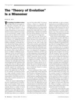
Photograph of the construction of the mat
foundation for the new Century Hotel in
San Francisco (1999).
Having had 25 feet of dredge spoils and
excavated soil stored on its construction site
may have saved Harvest States Cooperative up
to a half million dollars in construction costs on
its new Amber Milling facility in Houston,
Texas.
For about 20 years, the dredged material from
nearby waterways and excavated soil from a
neighboring project sat on the mill site. The
material acted as a surcharge which compacted
the soil to the point of allowing for mat
foundations and shallow footings instead of
more traditional pile foundations.
Without the need for 60- to 80- foot piles, the
shallow foundations also allowed construction
without disturbing contaminated soils below.
Most mat foundations employ a constant thickness ‘T’. This type of constant thickness is
called a flat plate mat.
A A
A - A
In most tall and large buildings, the mat thickness
T varies with the load. Therefore, the Engineer
may desire to separate the various sections of the
structure.
Mats have been used for centuries:
Assyrians joined ceramic blocks with asphalt.
Chinese joined large stones with keys of
molten lead.
Romans joined stones with hydraulic cements.
Today, we exclusively use reinforced concrete.
Many buildings are designed for multi-purposes, such as the one shown above, where a light
structure is required for offices, versus heavier structural frames are required for the ware-
house. The dilatation joint between them helps isolate the structures, but not the soil reactions.
Therefore, a mat foundation may be a solution to minimize the coupled actions.
When large column loads must be designed to prevent shear, other thickening designs are
common. Below are some typical flat plates with thickening under the columns.
Slab with basement walls acting as stiffness for the mat grillages.
Details of a mat foundation, serving as the slab of a one-story basement.
Compensated mat foundations.
If zero settlement is desired, the excavated soil weight will be equal to the weight of the
building, that is, the Engineer must excavate to a depth D
f
,
D
f
= Q / A γ (for a fully compensated foundation)
or D
f
< Q / A γ (for a partially compensated foundation)
q
o
= Q/A - γ D
f
Example 1.
A mat foundation is being designed for a small office building with a total live load of 250 kips
and dead load of 500 kips. Find: (a) the depth D
f
for a fully compensated foundation, (b) the
depth D
f
if a soft clay with γ = 120 pcf, c
u
= 100 psf and q
all
= 1 ksf with FS = 3, and
(c) the settlement under mid-mat for the partially compensated mat shown if D
f
= 2 ft.
A
60'
40'
Plan
2'
2'
16'
8'
Sand
Sand
Clay
Sand
60' x 40'
Q = DL + LL = 750 kips
density = 100 pcf
density (sat) = 100 pcf
density (sat) = 125 pcf
Cc = 0.25
eo = 0.9
density (sat) = 119 pcf
Part (a). A fully compensated foundation requires, in dry sand,
Part (b). For the soft clay,
q
u
= 5.14 c
u
(1 + 0.195 B / L)(1 + 0.4 D
f
/ B) = q
all
FS
Part (c). For the partially compensated case,
q
o
= Q/A - γ D
f
= (750x10³) / (60x40) – (100)(2) = 112.5 psf
3
(250500)10
3.13
(60)(40)(100)
f
Qlb
Dft
Aftftpcfγ
+
===
5.14(11.095)(10.4)
(1)(3)
0.94
f
u
all
f
f
D
B
c
LB
qFS
Q
D
A
Dfeet
γ
++
∴==
−
∴=
The average pressure increase in the clay layer is,
Using Boussinesq’s modified curves for L/B ≠ 1 (on the next slide),
1) At the top of the clay layer, z/B = 18 ft / 40 ft = 0.45 and L/B = 60 ft / 40 ft = 1.50
2) At the middle of the clay layer, z / B = 22 ft / 40 ft = 0.55 and L/B = 60 ft / 40 ft = 1.50
3) At the bottom of the clay layer, z / B = 26 ft / 40 ft = 0.65 and L/B = 60 ft / 40 ft = 1.50
(4)
6
topmiddlebottom
avg
qqq
q
++
∆=
0.82(0.82)(112.5)(0.82)92.3
top
topo
o
q
fromthechartsothereforeqqpsf
q
∆
=∆===
0.70(0.70)(112.5)(0.70)78.8
middle
middleo
o
q
qqpsf
q
∆
=∴∆===
0.62(0.62)(112.5)(0.62)69.8
bottom
bottomo
o
q
qqpsf
q
∆
=∴∆===
Boussinesq’s pressure distribution.
Increase of stress under the center of a
flexibly loaded rectangular area.
z/B
?q / q
o
Q
(92.34(78.8)69.8)
79
6
avg
qpsf
++
∆==
Therefore, the average pressure increase in the clay layer is,
The pressure p
o
at the center of the clay layer is,
p
o
= γ
sand
h
sand
+ γ’
sand
h’
sand
+ γ’
clay
h’
clay
= (100)(4) + (100–62.4)(16) + (125-62.4)(8 ft/2) = 1,252 psf
Finally, determine the settlement ?H,
(8')(12)(0.25)(1252)(79)
log[]log[]0.34
11(0.90)(1252)
oavg
c
oo
pq
HC
Hinches
ep
+∆
+
∆===
++
Analysis of Rigid Mats.
The analysis of a mat by assuming that it is rigid simplifies the soil pressures to either a
uniform condition or varying linearly. This is attained by not permitting R (the resultant force)
to fall outside the kern of the mat. Hence, the corner stress is,
σ = R / BL (1 ± 6 e
x
/ L ± 6 e
y
/ B)
Analysis and Design Procedure for Rigid Mats.
1) Calculate total column load, Q = Q
1
+ Q
2
+ Q
3
…...;
2) Determine the pressure on the soil q, at the mat’s invert,
3) Compare the resulting soil pressures with the allowable soil pressure;
4) Divide the mat into several strips in the x and y directions;
5) Draw the shear V and the moment M diagrams for each strip in both directions;
6) Determine the effective depth d of the mat by checking for diagonal tension shear at the
columns (ACI 318 11.12.2.1c);
7) From the all the moment diagrams of all the strips in one direction, choose the maximum
positive and negative moments per unit of width; and
8) Determine the areas of steel per unit width for the positive and the negative reinforcement in
both directions.
y
x
xy
Mx
My
Q
q
AII
=±±
Once the stress distribution is known for a rigid mat, the shears V and moment M can be
found,
V = S Qi – ∫ σ dx
M = S (Qi xi) – ∫ σ x dx
The loads Qi do not usually include the mat weight, but should be in the final iteration. The
assumption of linear distribution is conservative for rigid mats, and yields satisfactory results.
Analysis of Semi-Rigid Mats.
Mats are rarely completely rigid, since the cost would be prohibitive. Some differential
settlement must be admissible, without making the mat so flexible that shear reinforcing
becomes necessary. There are various methods of analysis for a semi-rigid mat:
(a) as a rigid mat,
(b) as a row of independent strips or beams,
(c) as a grid,
(d) using an elastic mat theory (for example, Hetenyi’s), and
(e) employing a finite element software.
Method (a) as a Rigid Mat is admissible when:
1. Column loads differ by less than 20% from each other,
2. Column spacing is very similar throughout,
3. The building superstructure is very rigid, and,
4. The load resultant R falls within the kern.
Method (b) of Independent Strips or Beams.
The mat is represented as strips along column centerlines and each strip is analyzed
as an independent elastic beam. Each column contributes an equal load to each contiguous
strip, and thus pressures vertical displacement compatibly.
Analysis of Semi-Rigid Strips (Conventional Method).
The pressure under the mat is assumed to be linear,
Consider each strip as a combined footing. Adjust so that equilibrium is satisfied with V ≅ 0
between strips). Analyze as a beam on an elastic foundation.
1
[]
y
x
i
xy
ex
ey
AII
=±±
For cases A, B and C (shown below), the reaction suggestion by Seiffert may be used.
Example 2.
Using the Independent Strip Method, analyze and design the 16.5 m by 21.5 m mat shown in
the figure on the next slide. Given that f’
c
= 20.7 MN/m
2
, f
y
= 413.7 MN/m
2
, with a load
factor = 1/7.
Solution.
Divide the mat into 3 strips AGHF, GIJH, and ICDJ, where
Strip AGHF, B
1
= 4.25 m,
Strip GIJH, B
2
= 8 m, and
Strip ICDJ, B
3
= 4.25 m.
A
G
B I
C
4.25
8 4.25
400 500 450
1500
1500
1200
1500 1500 1200
400 500 350
F
H E J
D
8m 8m
0.25
0.25m
0.25m
7m
7m
7m
x
ey = 0.10
ex = 0.44
kN
kN
kN
m
y