LTL-X Mark II RETROREFLEKTROMETER User Manual
Bạn đang xem bản rút gọn của tài liệu. Xem và tải ngay bản đầy đủ của tài liệu tại đây (2.71 MB, 50 trang )
LTL-X Mark II RETROREFLEKTROMETER
User Manual
On site quality control of road markings & road surfaces in accordance with CEN / ASTM
DELTA · Venlighedsvej 4 · 2970 Hørsholm · Denmark · Tel. +45 72 19 40 00 ·
DISCLAIMER
The information contained in this document is subject to
change without notice.
DELTA LIGHT & OPTICS MAKES NO WARRANTY OF
ANY KIND WITH REGARD TO THIS MATERIAL, INCLUDING, BUT NOT LIMITED TO, THE IMPLIED WARRANTIES
OF MERCHANTABILITY AND FITNESS FOR A PARTICULAR PURPOSE. DELTA LIGHT & OPTICS SHALL NOT BE
LIABLE FOR ERRORS CONTAINED HEREIN OR FOR
INCIDENTAL OR CONSEQUENTIAL DAMAGES IN
CONNECTION WITH THE FURNISHING, PERFORMANCE
OR USE OF THIS MATERIAL.
LTL-X Mark II IS BUILT ON GENERAL PUBLIC LICENSE
COMPONENTS. THE SOURCS CODE IS AVAILABLE
UPON REQUEST.
Caution: Changes / modifications not approved by the responsible party could void the user’s authority to operate the
equipment.
NOTE: This equipment has been tested and found to comply
with the limits for a Class A digital device, pursuant to part
15 of the FCC Rules. These limits are designed to provide
reasonable protection against harmful interference when the
equipment is operated in a commercial environment. This
equipment generates, uses, and can radiate radio frequency
energy and, if not installed and used in accordance with the
instruction manual, may cause harmful interference to radio
communications. Operation of this equipment in a residential
area is likely to cause harmful interference in which case the
user will be required to correct the interference at his / her
own expense.
Visit our web-site: www.roadsensors.com
GUI 2.00, June, 2015
Version 1.2b English
2
LTL-X Mark II Retroreflectometer
DELTA
DELTA
LTL-X Mark II Retroreflectometer
3
4
LTL-X Mark II Retroreflectometer
DELTA
TABLE OF CONTENTS
SECTION 1................................................................................................................................ 7
OPERATING INFORMATION ...................................................................................................... 7
LTL-X Mark II introduction ..................................................................................................................... 7
LTL-X Mark II retroreflectometer features .............................................................................................. 8
Getting started ........................................................................................................................................... 9
Height adjustment ................................................................................................................................ 9
Buttons ................................................................................................................................................. 9
Turn on ................................................................................................................................................. 9
Measuring ............................................................................................................................................ 9
User select (user initials) .................................................................................................................... 10
Series Id select (name) ....................................................................................................................... 10
Errors and warnings ........................................................................................................................... 10
Miscellaneous .................................................................................................................................... 10
Data exchange / communication ........................................................................................................ 11
Important guide lines for the correct use of the LTL-X Mark II............................................................. 11
Positioning of the instrument on the road marking ............................................................................ 11
Taking the measurement .................................................................................................................... 11
Number of measurements. ................................................................................................................. 11
Protection of the display/display shield. ............................................................................................ 11
SECTION 2.............................................................................................................................. 12
GENERAL INFORMATION ........................................................................................................ 12
The measurement .................................................................................................................................... 12
Errors and warnings ................................................................................................................................ 12
Optical principle ..................................................................................................................................... 12
Notes on error sources ............................................................................................................................ 13
High temperature conditions. .................................................................................................................. 14
Display ............................................................................................................................................... 14
Battery ................................................................................................................................................ 14
SECTION 3.............................................................................................................................. 15
THE USER INTERFACE .............................................................................................................. 15
Display and keyboard layout .................................................................................................................. 15
Measurement display .............................................................................................................................. 15
Upper icon row ....................................................................................................................................... 15
Lower icon row ....................................................................................................................................... 16
Push buttons ............................................................................................................................................ 16
The menu tree ......................................................................................................................................... 18
SETTING UP FOR MEASUREMENTS ...................................................................................... 19
Selecting a User Id .................................................................................................................................. 19
Selecting a user. ................................................................................................................................. 19
Selecting a road marking icon ................................................................................................................ 21
The purpose of the road marking icon. .............................................................................................. 21
Deactivating the profile icon. ............................................................................................................. 21
Setting the date and time ......................................................................................................................... 21
Setting the time format ....................................................................................................................... 22
Setting the date format ....................................................................................................................... 22
Adjusting the time and date ............................................................................................................... 22
Setting the dimmer and back light for the display .................................................................................. 23
Setting the sound..................................................................................................................................... 23
Auto Sleep (Power) ................................................................................................................................. 24
Setting the language ................................................................................................................................ 24
Setting the temperature unit .................................................................................................................... 24
Setting the SMART key function ........................................................................................................... 25
Setting the AUX functions / GPS ........................................................................................................... 25
Activating the GPS ............................................................................................................................ 26
More about the GPS ........................................................................................................................... 26
Setup (basic / advanced) ......................................................................................................................... 27
DELTA
LTL-X Mark II Retroreflectometer
5
MEASURE TYPE ........................................................................................................................... 28
Wet timer ................................................................................................................................................ 28
Timer Alarm ........................................................................................................................................... 28
Series id ............................................................................................................................................ 29
Working with Series Id ........................................................................................................................... 29
The purpose of a Series Id.................................................................................................................. 29
Activate Series ........................................................................................................................................ 29
Selecting a Series Id ................................................................................................................................ 29
Enter a new Series Id .............................................................................................................................. 30
Edit a Series Id ........................................................................................................................................ 30
Removing a Series Id .............................................................................................................................. 30
Presetting the road marking icon ............................................................................................................ 31
The log .............................................................................................................................................. 32
Clearing data in the log ........................................................................................................................... 32
Viewing the log....................................................................................................................................... 33
View series data. ..................................................................................................................................... 34
OTHER SETTINGS ....................................................................................................................... 35
Average function .................................................................................................................................... 35
AVERAGE: ....................................................................................................................................... 35
TYPE: ................................................................................................................................................ 35
NUMBER: ......................................................................................................................................... 35
RESET: .............................................................................................................................................. 35
Editing names ......................................................................................................................................... 36
Auto print ................................................................................................................................................ 36
Diagnostics ............................................................................................................................................. 36
The help system ...................................................................................................................................... 36
SECTION 4.............................................................................................................................. 37
MAINTENANCE ............................................................................................................................ 37
General care ............................................................................................................................................ 37
Protection window .................................................................................................................................. 37
Battery .................................................................................................................................................... 37
Replacing the battery ......................................................................................................................... 38
Battery status ...................................................................................................................................... 39
Fuses ....................................................................................................................................................... 39
Lamp ....................................................................................................................................................... 39
Calibration .............................................................................................................................................. 40
Calibration procedure ......................................................................................................................... 40
Verification procedure ....................................................................................................................... 42
Keep the calibration ceramic in good condition! ............................................................................... 42
Calibration service ............................................................................................................................. 42
Printer ..................................................................................................................................................... 43
Replacing paper ................................................................................................................................. 43
Mounting the wet night rails for rain measurements .............................................................................. 44
Mounting the wheel unit ......................................................................................................................... 46
APPENDIX A .......................................................................................................................... 47
COMMUNICATION FACILITIES .............................................................................................. 47
RSC software program............................................................................................................................ 47
APPENDIX B .......................................................................................................................... 48
SPECIFICATION ........................................................................................................................... 48
General characteristics ............................................................................................................................ 48
Environmental characteristics ................................................................................................................. 49
Mechanical characteristics ...................................................................................................................... 49
APPENDIX C .......................................................................................................................... 50
DELIVERY ..................................................................................................................................... 50
6
LTL-X Mark II Retroreflectometer
DELTA
SECTION 1
OPERATING INFORMATION
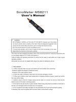
LTL-X Mark II introduction
The LTL-X Mark II retroreflectometer is a portable field instrument intended for measuring
the retroreflection and reflection properties of road markings. LTL-X Mark II measures the RL
value (coefficient of retroreflected luminance at night). RL is a measure of the lightness of the
road marking as seen by drivers of motorized vehicles in car headlight illumination. The road
is illuminated at an angle of 1.24The reflected light RL at an angle of 2.29, which corresponds, to an observation distance of 30 meters. This is relevant for a motorist’s viewing situation under normal conditions. Further information on measuring principles and standards can
be located on: www.roadsensors.com.
RL is an important factor in the ON-SITE quality control of road markings.
Figure 1. The instrument
The operation of the retroreflectometer is very simple and requires minimal instruction.
The LTL-X Mark II measures the retroreflectivity and calculates RL according to the international CEN and ASTM standards like EN 1436, ASTM E 1710, ASTM E 2177 and ASTM E
2832. Results are presented in plain text on a large graphic display. Error messages or warnings are shown in the display in case of any problems during use.
The memory of the instrument provides registration of measurements with corresponding
DELTA
LTL-X Mark II Retroreflectometer
7
date, time and following data (if enabled):
Name of measuring series (road name)
Profile icon for road marking type
User name
GPS data (if installed)
Temperature & humidity
Instrument status
The measurement results can be printed by the built-in printer. Communication with a PC using the LTL RSC (Road Sensor Control) software program (see pg. 47) allows for data exchange with other PC programs.
A rechargeable NiMH (Nickel-Metal Hydride) High capacity battery powers the LTL-X Mark
II, allowing approx. 2.500 measurements on a new and fully charged battery. A mains powered 15V power adaptor for charging (the instrument has a built-in charging circuit) is supplied as customary delivery. Charging time is approx. 3½ hour. The instrument can also be
charged from a 15-18 VDC source. For field charging the 15V power supply could be powered from an “AC power inverter” connected to the car battery.
LTL-X Mark II retroreflectometer features
Portable instrument
Ergonomic operation height
Fast measurement. Completed in approximately 1 sec.
Measuring on dry and wet surfaces as well as under continuous wetting
Flat, textured & profiled markings
Fully documented measurements with automatic data storage, user and series identification for labeling and grouping measurements
Audible signals during use (if enabled)
Easy one-step calibration procedure
Traceable and accredited calibrated reflection standard
User replaceable battery
Battery charging time is approx. 3½ hour for high capacity battery pack
Rechargeable from mains using power adapter
Average calculation of 2 to 99 readings
Multiple languages
RSC (Road Sensor Control) PC software for data exchange. Logged data can
easily be exported to applications such as Microsoft Excel or displayed on Goggle Earth
LTL-X Mark II comes as customary delivery with extendable handle, wheels, built-in printer
and built-in GPS.
8
LTL-X Mark II Retroreflectometer
DELTA
Getting started
Height adjustment
Before using the LTL-X Mark II, notice that the operating panel can be adjusted in height
for ergonomic considerations. The height is adjusted by pressing the red knob on the front
of the instrument and at the same time lifting the handle on the operating panel. Release
the knob and continue lifting until the handle locks.
Buttons
HELP
ON/OFF
MENU
SMART
HOME
CALIBRATE
BACK
UP
LEFT
RIGHT
OK (center)
DOWN
Figure 2.Buttons
For more information about buttons: see pg. 16
Turn on
Switch on the LTL-X Mark II by pressing and holding the ON/OFF button
until the
display turns on. The instrument will be ready for measuring within 10-12 sec from cold.
From idle the instrument will be ready within 1 sec.
Measuring
Calibrate the instrument if necessary. DELTA recommends calibrating the instrument every time the instrument is switched on and / or starts a new series of measurements or minimun once a day typically in the morning before measurements start. See Calibration, pg. 40.
Place the instrument on the road marking. See positioning on the road, pg. 11
Press the green OK-button
in approx. 1 sec.
to take the measurement. A measurement will be finished
When the measurement is complete the display will be updated with information from the
measurement. Data is automatically transferred to the data log. If there is a problem with
the measurement a warning icon or an error icon will pop up (see Errors and warnings, pg. 10)
and an audible alarm will sound (if enabled, see Sound settings, pg. 23 ).
DELTA
LTL-X Mark II Retroreflectometer
9
Measurements taken with a low battery warning are marked in the log and a warning icon
appears. If battery voltage gets too low measurements can’t be taken and an error icon appears.
To print out the last measurement data, press the PRINT button
.
User select (user initials)
If the User icon
is displayed in the upper icon row on the measuring display, press the
UP button ▲ (and if necessary ◄ or ►) to mark the user icon. Press the OK-button
to
enter the user select menu.
icon is not shown or if further information is need, see User Id, pg. 19.
If
Series Id select (name)
If the Series Id icon
is displayed in the upper icon row on the measuring display press
the UP button ▲to mark the road icon. Press the OK-button
lect menu. Choose SELECT to use a name from the list.
If the
to enter the Series Id se-
icon is not shown or if further information is need, see Series Id, pg. 29.
Errors and warnings
An error or warning icon will appear in the upper row of the display if the LTL-X Mark II
detects a problem.
Press the UP button ▲ to get a description of the most serious error or warning. Now press
the OK-button to display a total list of all errors or warnings related to the measurement and
the instrument in general.
Miscellaneous
The HOME screen can be activated at any time by pressing the HOME button
.
Reset log:
Press the MENU button
and select LOG and CLEAR DATA, Now select from the menu:
CLEAR LAST DATA, CLEAR ALL DATA or CLEAR SERIES DATA.
Date and time:
Press the MENU button
and select SETTINGS AND DATE & TIME. Choose SET TIME/DATE.
Use the UP ▲ and DOWN ▼ buttons to set the different time related settings.
Power save:
Press the MENU button
and select SETTINGS and POWER. Choose AUTO SLEEP or
AUTO OFF. Use ▲and ▼ to edit the values.
10
LTL-X Mark II Retroreflectometer
DELTA
Data exchange / communication
The RSC software program, developed by DELTA for use on a PC, allows data to be exchanged between the LTL-X Mark II and a PC. See RSC-program, pg. 47.
Important guide lines for the correct use of the LTL-X Mark II
Positioning of the instrument on the road marking
Select an area of the pavement marking that is level when taking readings. The measurement
field is marked with a yellow sticker on one side of the base cover. The measurement field is
approximately 45 mm / 1.77 inch wide and 200 mm / 7.87 inch long. Ensure that the pavement marking to be measured is free of debris before taking measurements. Make sure that
the instrument is stable positioned.
Reason: The LTL-X Mark II has three support pads, each with a small footprint, two smaller
in the front and one larger at the back. An uneven marking or a small piece of gravel trapped
below one of the pads will move the measurement field and affect the reading.
Taking the measurement
Press the OK-button
to take a reading. Do not put pressure on the handle when taking a
measurement.
Reason: Pressure on the handle can tilt the instrument slightly and affect the measurement
geometry and therefore influence the reading.
Number of measurements.
For accurate readings, do not take just one reading of a road marking. Three readings will
give a more accurate result than one reading. Five readings will give an even more accurate
result than three readings, etc. Take the readings in adjacent areas of the marking. Let the instrument calculate the average of the readings (fixed or moving average options). See pg. 35
Reason: A road marking’s retroreflectivity varies from area to area. It is not unusual to see
variations of 5% - 20% when the instrument is moved even less than 12 mm / ½” in either
direction.
Protection of the display/display shield.
For the protection of the display and longevity of the instruments keep the display shield
closed when the instrument is not used. For further information please see High temperature conditions, pg. 14.
Remember:
LTL-X Mark II is an optical precision instrument, handle with care.
Keep the protection window and calibration unit clean and undamaged.
Store in a clean, dust free and dry environment.
Read:
“Measurement practice for road markings”. This leaflet can be located on:
www.roadsensors.com under “Technical Background” and “Introduction”
DELTA
LTL-X Mark II Retroreflectometer
11
SECTION 2
GENERAL INFORMATION
The measurement
The LTL-X Mark II retroreflectometer measures the RL (coefficient of retroreflected luminance) parameter. The RL parameter represents the brightness of road markings seen by drivers of motor vehicles by headlight illumination.
In the LTL-X Mark II the illumination angle is 1.24 degrees for RL. The observation angles
are 2.29 degrees. According to both ASTM and CEN standards these angle simulates a driver’s viewing distance of 30 meters. The instrument’s illumination field is approximately
200 mm x 45 mm / 7.87 x 1.77 inch.
The LTL-X Mark II is controlled by multiple microprocessors. It is operated with an extractable keyboard located at the top of the retroreflectometer.
Push the
button to take a measurement. Shortly after, the RL and related information are
presented on the color display. The result is automatically transferred to the internal memory.
The measurement, along with its corresponding time, date, and other data can be printed using
the built-in printer.
Each time a measurement is taken, a status information is generated. If any error occurs the
information can be interpreted by the warning/error icon in the top line of the display. The
information is available until a new measurement is taken or the problem is resolved. The status information is also stored in the log.
Errors and warnings
When a measurement is taken, a warning text is generated if a problem arises and saved in the
log together with the measurement. If a problem occurs, a warning icon
or an error icon
is show above the HOME screen and an audible alarm is sounded (if enabled) and the
warning / error information are stored in the log.
To view the nature of the problem, press the UP button and the warning/error icon will be
highlighted. The most severe problem will be stated in the message line underneath.
Then press the OK button to view a total list of problems starting with the most severe.
Press the BACK button to return to the HOME screen. If the problem did not hinder the completion of the measurement, the erroneous value(s) will be stored in the log. If an error is registered the measurement will not be stored in the log.
When printing out, on the built-in printer, or transferring logged data to a PC using the RSC
program, any trouble will be shown in clear text on the concerned measurement.
Optical principle
The optical system in the LTL-X Mark II is covered by a patent. A LED lamp in the top of the
tower generates the light for the RL measurements. After a field stop the light is collimated by
a lens and deflected through a mirror toward the road.
12
LTL-X Mark II Retroreflectometer
DELTA
The reflected light from the road uses the same mirror and lens. Between the lens and the photo detector field aperture, stops define the observation area. The illumination field is inside in
the observation field. This is important to assure correct measurement on profiled markings.
V spectral correction is achieved by use of advanced optical filters.
Notes on error sources
Stray light can occasionally enter the instrument but will be insignificant under normal measurement conditions. Before each measurement, the LTL-X Mark II automatically evaluates
the leakage and compensates for it before the readout. In case of a significant leakage level, a
warning or error message is given and special precautions may be necessary.
Instrument leak, drift and offset errors are compensated by means of data obtained during the
calibration procedure. It is very important to keep the protection window and the ceramic on
the calibration unit clean.
The LTL-X Mark II illumination angle is 1.24° relative to the road surface. Because of this
small angle accurate placement on the road is important. Avoid pebbles and abnormal irregularities. The LTL-X Mark II must be parallel and in contact with the marking surface.
The LTL-X Mark II retroreflectometer is a rugged instrument, but it is an optical instrument
and must be handled as such.
The LTL-X Mark II is factory calibrated. Nevertheless start measurements with a calibration.
Study the display for any warning or error icons. See also Section 4 – Maintenance, pg. 37
Note
Keep the protection window and ceramics on the calibration unit clean.
Keep the battery fully charged. A well charged battery is more resistant to aging and damage.
DELTA
LTL-X Mark II Retroreflectometer
13
High temperature conditions.
Display
If the display is exposed to intense direct sunlight during a longer period of time the display
could become overheated. It is recommended to close the protective display shield. The shield
also protects against damages and scratches. "Daylight readable" displays are vulnerable to
high temperatures. High temperature will decrease the display service life.
Battery
The battery is rated to operate between 0C / 32F and 45C / 113F.
14
LTL-X Mark II Retroreflectometer
DELTA
SECTION 3
THE USER INTERFACE
Figure 4: The display
Display and keyboard layout
The user interface consists of a rectangular display surrounded by push buttons.
The display has two main modes: the measurement display (HOME screen) and the menu display. The instrument will start up with the measurement display shown. The display area is
divided into four areas: a large main display in the middle, an icon row at the top, a message
or caption field underneath and an icon row at the bottom.
Measurement display
Here the last measured RL value is presented with large digits together with other information
from the measurement. On the graphic in figure 4, all available information’s are shown in the
display. If a function is deactivated, it will not be shown. The actual date and time are always
shown.
Upper icon row
The upper row of icons is accessed by pressing the UP button ▲. One of the icons is then
highlighted and can be activated by pressing the OK-button. The other icons in the row can be
accessed by using the LEFT ◄ or RIGHT ►buttons. The meanings of the icons are (from left
to right):
Series Id selection, can be switched off (see pg. 29).
User Id selection, can be switched off (see pg. 19).
Error/warning alarm. Will be shown in case of an error/warning (see pg. 10).
GPS indication (see pg. 25).
Battery status (see pg. 39).
DELTA
LTL-X Mark II Retroreflectometer
15
Lower icon row
From the lower icon row you can select a road marking icon that will be saved together
with the measurement in the log for future measurement identification. Access the icons
by pressing the DOWN button ▼. Use the LEFT or RIGHT button to mark the preferred
icon. Pressing DOWN again shows more icon rows from a roll stack of four rows. One
row, marked with a "PR" for "Preset" can be preset by the user (see pg. 31) and is saved
separately for each measuring series. It will be the active icon row, ready for selection,
when a measuring series is selected.
Activate the marked icon with the OK-button or exit with the HOME
or UP ▲ button.
The selected icon is now shown in the left side of the HOME screen and the instrument
is again ready for measuring.
Other functionality regarding the lower icon row:
Activating an already selected icon will cancel the activation and remove the icon from
the main display (and no icon will be saved with the next measurement).
Push buttons
OK
When the message row shows MEASURE, press the OK-button to take a measurement. In most
other cases pressing the OK-button will activate a highlighted selection.
ON/OFF
The button turns the instrument ON or OFF. Press the button to turn the instrument ON. It
will take 10-12 seconds from cold start, warm start within 1 sec. before the main menu is
shown and the instrument is ready to operate.
To turn the instrument OFF, hold down the button about 4-5 second. If the ON/OFF button
is held less than 4 seconds the instrument will enter standby mode and turn off the display.
From standby mode, a short press on the
button will wake up the instrument and turn on
the display.
It is not possible to turn off the instrument during battery charging or when connected to a
USB port.
HOME
Bring you back to the measurement display.
BACK
Bring you backward one step in the menu and cancel new settings, which have not yet been
confirmed by the OK button. In most cases the LEFT ◄ button has the same function.
Pressing BACK from the HOME screen will, in most cases, jump to the last used menu / sub
menu point.
16
LTL-X Mark II Retroreflectometer
DELTA
HELP
The button presents a context sensitive help text. The help presented will be on the subject
headline shown in the display. Another press on the button will open up a general help menu.
Menu
The button selects the top level of the menu tree, see pg. 18 (the main menu). Use the UP and
the DOWN buttons to scroll through the menu items. Press OK to select the highlighted item.
In most cases it opens up further submenu levels.
SMART
This button is user programmable to one out of several functions, e.g. to clear the last measurement, see pg. 25.
CALIBRATE
This button starts the calibration wizard, see pg. 40.
Print out the last measurement or selected parts of the log to the internal printer. In the diagnostics menu you can print out different instrument information’s.
DELTA
LTL-X Mark II Retroreflectometer
17
The menu tree
MAIN MENU:
SETTINGS
MEASURE TYPE
SERIES-ID
LOG
AVERAGE
DIAGNOSTICS
HELP
AUTOPRINT
SETTINGS:
USER
DATE & TIME
DISPLAY
SOUND
POWER
LANGUAGE
TEMPERATURE
SMART
AUX
SETUP
MEAS. TYPE:
RL
WET TIMER
TIMER ALARM
SERIES-ID:
ACTIVATE
SELECT NEW
EDIT
DELETE
PRESET MARK
USER:
SELECT
EDIT
NEW
DELETE
SEL. AT START
DATE & TIME:
TIME FORMAT
DATE FORMAT
SET TIME/DATE
TIME ZONE
SYNC TO GPS
DISPLAY:
BACKLIGHT
DIMMER
DIM LEVEL
BACKGROUND
SOUND:
KEY CLICK
SOUNDS
BEEP
LOG:
CLEAR DATA
VIEW LOG
POWER:
AUTO SLEEP
AUTO OFF
AVERAGE:
AVERAGE
TYPE
NUMBER
RESET
AUX:
GPS
DIAGNOSTICS:
INSTRUMENT
BATTERY
BOARDS
GPS
SYSTEM
CLEAR LOG:
LAST DATA
ALL DATA
SERIES DATA
VIEW LOG:
LAST DATA
ALL DATA
SERIES DATA
HELP:
HELP ON KEYS
HELP ON MENU
HELP ON MEASUREMENT
HELP ON SERIES SELECT
ROAD MARKING SELECT
HELP ON USER SELECT
HELP ON EDITING
HELP ON AVERAGING
HELP ON GPS
HELP ON SETTINGS MENU
HELP ON SERIES-ID MENU
HELP ON LOG MENU
Figure: 5 – The menu tree
18
LTL-X Mark II Retroreflectometer
DELTA
SETTING UP FOR MEASUREMENTS
Selecting a User Id
The User Id (user profile) is used to identify the operator and is saved in the log together with
each measurement. If enabled, it can be seen at the lower left side of the measurement display.
Measurements can also be taken without a User Id. Unlimited User Id’s can be stored in the
instrument.
Certain instrument settings are stored individually for each user. Selecting a user will restore
these settings. Following settings are stored:
User, sel at start
Sound level
Time format
Beep (on/off)
Sync to gps
Activate series
Backlight time
Average (on/off)
Dimmer time
Average type
Dim level
Average number
Background (on/off)
Wet timer
Key repeat (time)
Wet timer alarm/measure
Setup (basic/advanced)
Calibration value
Auto off time
Temperature (°c/°f)
Auto sleep time
Languages
Key click sound level
Smart key
Selecting a user.
If the user select icon
Press the
DELTA
is not seen in the upper icon row:
button and select SETTINGS / USER / SELECT to display the USER menu.
LTL-X Mark II Retroreflectometer
19
If the user select icon
is seen in the upper icon row:
Press the UP button. Then, if necessary, use the LEFT or RIGHT button to highlight the user
icon. Press the OK button. The USER menu is shown:
Now use the UP or DOWN button to highlight a user name. Press the OK button to select the
user.
Changes made to the above mentioned individual instrument settings are automatically stored
in the selected User Id.
Selecting OFF will deactivate the user function and set all individual instrument settings to
default.
Edit user
User names can be edited from the menu SETTINGS / USER / EDIT (see editing pg. 36).
New user
A new user can be made from the menu SETTINGS / USER / NEW (see editing pg. 36).
Clear user
Deleting the User Id will remove the user and settings from the memory.
Select at start
Enabling SEL. AT START will force the user to select a User Id each time the LTL-X MARK
II is turned on.
Press the MENU button and select SEL. AT START. Press OK to toggle between YES and NO
20
LTL-X Mark II Retroreflectometer
DELTA
Selecting a road marking icon
The purpose of the road marking icon.
The road marking icons are used as labels for the individual measurement corresponding to
the measured road marking and will be saved in the log together with the measuring result.
The icon will be presented together with the corresponding measurement when viewing the
log, print out or in the RSC program (see pg. 47).
There are 24 fixed icons to select from. Six of the icons can be programmed as individual presets for each series (see pg. 31) and will be ready for selection when a series is selected.
Selecting an icon.
From the HOME screen press the DOWN button. Then use the LEFT or RIGHT button to highlight the wanted icon. Pressing DOWN button steps through and displays the four icon rows.
Pressing UP button will return to the HOME screen without selecting a new icon.
Pressing the OK button will activate the selected icon. The selected icon is now shown in the
left side of the measuring field and the instrument is again ready for measuring.
Deactivating the profile icon.
Activating an already selected marking icon will cancel the activation and remove the icon
from the main display.
Setting the date and time
Date and time is always shown in the display. Every measurement taken is stamped with the
date and time, so it is essential that the settings are correct.
Press the MENU button and select SETTINGS / DATE & TIME. Press OK and the time format sub
menu is shown.
DELTA
LTL-X Mark II Retroreflectometer
21
Setting the time format
Press OK when TIME FORMAT is highlighted and toggle between 12 and 24 hr format by
pushing the OK button.
Setting the date format
Navigate to DATE FORMAT and press OK.
Highlight the preferred date format using UP or DOWN. Press OK to accept.
Adjusting the time and date
Press OK when SET TIME/DATE is highlighted.
Press OK to activate each line and use UP or DOWN to set the figure. Press OK to accept the
setting.
Note: the time in this menu is not live updated, but it will synchronize the time shown in the
HOME screen.
22
LTL-X Mark II Retroreflectometer
DELTA
Setting the Time zone
Press OK when TIMEZONE is highlighted. Press OK to open the list of geographical locations. Choose your area. Press OK to select. Now a new list shows up with national time
zones. Scroll to your location and press OK to select.
Time zone is used in relation with automatic daylight saving and When SYNC. TO GPS is enabled.
Note:
Be aware that if the time zone is changed, the recorded time stamp in the
logged data will be updated to the new time zone.
Synchronize to GPS
When SYNC. TO GPS is highlighted press OK to toggle between ON and OFF. By activating
this function make sure that the time zone is correct otherwise the clock in the LTL-X Mark II
and the time stamp in the log data will probably not be correct.
Setting the dimmer and back light for the display
The backlight and dimmer can be adjusted. Press the MENU button and select SETTINGS /
DISPLAY.
The levels can be adjusted on a scale from 1 (lowest intensity) to 10. Press OK to activate the
function and use UP and DOWN to change the values. Press LEFT or BACK to store.
It is also possible to adjust the time before the light switch to dimmer mode from 5 to 120
seconds or set to OFF.
The BACKGROUND option toggles the background colour of the display.
Note: Using high backlight intensity will drain the battery faster!
Setting the sound
Press the MENU button and select SETTINGS / SOUND. Select KEY CLICK or SOUNDS to set
the individual sound levels for key click and system sounds. Use the UP or DOWN button to
set the level. Accept the setting by pressing the OK-button.
DELTA
LTL-X Mark II Retroreflectometer
23
To activate a high level beep when the instrument has finished measurement set BEEP to ON
by pushing the OK-button.
Note:
The beep indicates that the measurement is taken and the instrument can be
removed from the road marking. Data processing can be on going after the
beep and after a moment the display is updated.
Auto Sleep (Power)
To save power the instrument can be set to automatically change to Auto Sleep mode. The
Auto Sleep time can be set from 1 to 30 min. in intervals of 1 min. or it can be deactivated
(OFF). Startup will be instantaneous pushing the ON/OFF -button.
Press the MENU button and select SETTINGS / POWER / AUTO SLEEP. Use UP and DOWN to
edit the auto turn sleep time.
Auto Off (Power)
To save power, the instrument can be programmed to automatically shut down if not used for
a certain period of time.
Press the MENU button and select SETTINGS / POWER / AUTO OFF. Use UP and DOWN to edit
the auto turn off time. The off time can be set from 1 to 8 hours in intervals of 1 hour or it can
be deactivated (OFF).
When communicating with RSC program or when the charger is connected the instrument
will not power down automatically.
Setting the language
Press the MENU button and select SETTINGS / LANGUAGE. Use the UP or DOWN button to
select a language. Accept by pressing the OK button or leave unchanged by pressing BACK.
Setting the temperature unit
Press the MENU button and select SETTINGS / TEMPERATURE. Use the OK button to select between Celsius and Fahrenheit.
24
LTL-X Mark II Retroreflectometer
DELTA
Setting the SMART key function
This button is user programmable to one of several functions, e.g. to clear the last measurement. Press the MENU button and select SETTINGS / SMART.
Use the UP or DOWN button to select the SMART KEY function. Accept by pressing the
OK button.
The selected function is now accessed every time
is pressed
Setting the AUX functions / GPS
The AUX function is used to enable auxiliary built-in equipment like the GPS.
Using GPS
The GPS receiver is mounted inside the instrument. The GPS system is used to log position
data (latitude and longitude) together with the measurement data.
If activated a GPS icon is shown in the upper icon row
The icon will display the quality (reliability) of the GPS signal.
DELTA
LTL-X Mark II Retroreflectometer
25