Nghệ Thuật Gấp Giấy_ Gấp 1 CHIẾC XE MÁY VMAX PAPER CRAFT_ YAMAHA - P1
Bạn đang xem bản rút gọn của tài liệu. Xem và tải ngay bản đầy đủ của tài liệu tại đây (582 KB, 15 trang )
PAPER CRAFT
Thank you for downloading the "VMAX" paper craft model. By simply fol-
lowing this manual while referring to the names and numbers shown on the
parts sheets, you can assemble an authentic-looking replica of the VMAX.
Assembly instructions: Fifteen A4-sized sheets.
Paper craft: Sixteen A4-sized sheets with 174 parts in all
These instructions apply only to the "VMAX".
Other paper craft model instructions can be downloaded separately.
The parts are easier to work with when printed on strong, thick paper.
Assembly Instructions
Note
TO BEGIN
Item of Caution
*Take care when using sharp or pointed objects or when
using bladed cutting tools. Place a heavy sheet of paper
under the paper you want to cut.
*Use glue and other adhesives only in well-ventilated
areas.
*When printing, use a slightly reduced font size as there
are many differences in dimensions depending on the
type of printer used.
Tools and materials needed
-Ruler -Scissors - Blade cutter or "Exacto-knife" - Awl or
other pointed tool (for making a folding crease) - Felt
pen - Pin set - Glue - Hand towel ( for cleaning your
fingers) - Dictionary or other heavy book ( to press the
papers flat)
HOW TO ASSEMBLE
*Follow the working method and markings carefully.
*Cut carefully along the outter line with a cutting blade,
Exacto-knife or scissors.
*Cut carefully with a cutting blade, Exacto-knife or
scissors.
*For folding parts, first use an awl or other pointed
tool to make a light crease along the dotted or solid
line. This will make the folds straight. Avoid making
strong creases, as this will cause the paper to tear.
*As an adhesive, white, wood glue is recommended.
Avoid over application as this will cause the paper
to wrinkle.
*Before beginning assembly, test adhesive amounts
on extra paper.
*Occasionally, white spots will be apparent on folds
and cuts. Use a marker or pencil to fill-in these spots.
It is recommended that this be done after each stage
of assembly because coloring becomes more diffi-
cult once parts are assembled.
One - point Advice
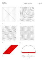
Basic working method and markings
Fold along these lines. The printed
surface should be on the outside of
the folded shape.
Solid lines
Dotted line
Fold along these lines. The printed
surface should be on the inside of
the folded shape.
Broken lines
Cut out parts marked with an as-
terisk (*).
Cut along these lines
Red dots are the reference positions
for gluing surfaces.
- 2 -
Do not fold or cut the parts
marked .
- 3 -
A-
1
Body
Sheet A, 1 part in total
Fold each relevant part according to the assembly symbols.
Reference photo
First, assemble each component by following the
working method and markings. Then, refer to the il-
lustration and photos below to glue the parts together.
Indication of
Working Methods
Fold or Curve
Glue
1 Assembling the Body
Reference photo
- 4 -
B-
3
B-
5
B-
6
B-
4
B-
9
B-
10
B-
13
B-
1
B-
12
B-
7
B-
14
B-
8
B-
11
B-
2
B-
15
B-
19
B-
18
B-
22
B-
21
B-
17
B-
16
B-
20
B-
24
B-
23
Apply glue on the area
indicated in the illustration.
Steering column
Sheet B, 24 parts in total
Fold each relevant part according to the assembly symbols.
First, assemble each component by following the
working method and markings. Then, refer to the il-
lustration and photos below to glue the parts together.
Indication of
Working Methods
Fold or Curve
Glue
2 Assembling the Steering Column
Please use the dots on each component as reference when gluing surfaces.
- 5 -
C-
1
C-
2
C-
2
D-
2
D-
1
Top cover
Sheet C, 2 parts in total
Fold each relevant part according to the assembly symbols.
First, assemble each component by following the
working method and markings. Then, refer to the il-
lustration and photos below to glue the parts together.
Indication of
Working Methods
Fold or Curve
Glue
3 Assembling the Top Cover and Intake
Please use the dots on each component as reference when gluing surfaces.
Reference photo
Fold and glue the parts making sure both tabs (illustrated
by dotted-lines) are neatly tucked in.
Intake
Sheet D, 2 parts in total
Fold each relevant part according to the assembly symbols.
Reference photo
- 6 -
E-
33 (
E-
35)
E-
36 (
E-
38)
E-
11 (
E-
9)
E-
7 (
E-
13)
E-
40 (
E-
42)
E-
26 (
E-
25)
E-
46 (
E-
47)
E-
5 (
E-
6)
E-
3 (
E-
4)
E-
20 (
E-
19)
E-
15 (
E-
16)
E-
21 (
E-
22)
E-
1 (
E-
2)
E-
37 (
E-
39)
E-
24 (
E-
27)
E-
41 (
E-
43)
E-
12 (
E-
10)
E-
8 (
E-
14)
E-
32 (
E-
34)
E-
29 (
E-
31)
E-
28 (
E-
30)
E-
44 (
E-
45)
E-
17 (
E-
18)
E-
23
Engine
Sheet E, 47 parts in total
Fold each relevant part according to the assembly symbols.
Please use the dots on each component as reference when gluing surfaces.
First, assemble each component by following the
working method and markings. Then, refer to the il-
lustration and photos below to glue the parts together.
Indication of
Working Methods
Fold or Curve
Glue
4 Assembling the Engine
* Make two of each part.
The diagram shows how the left part of
the engine looks. The numbers within
parentheses indicate parts for the right
part of the engine.
Reference photo
* Only the left part is available.
Left
Right