8.2.1.5 Lab - Designing and Implementing a VLSM Addressing Scheme - ILM
Bạn đang xem bản rút gọn của tài liệu. Xem và tải ngay bản đầy đủ của tài liệu tại đây (134.32 KB, 12 trang )
Lab – Designing and Implementing a VLSM Addressing Scheme
(Instructor Version)
Instructor Note: Red font color or Gray highlights indicate text that appears in the instructor copy only. Optional
activities are designed to enhance understanding and/or to provide additional practice.
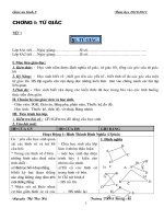
Topology
Objectives
Part 1: Examine Network Requirements
Part 2: Design the VLSM Address Scheme
Part 3: Cable and Configure the IPv4 Network
Background / Scenario
Variable Length Subnet Mask (VLSM) was designed to avoid wasting IP addresses. With VLSM, a network is
subnetted and then re-subnetted. This process can be repeated multiple times to create subnets of various
sizes based on the number of hosts required in each subnet. Effective use of VLSM requires address
planning.
In this lab, use the 172.16.128.0/17 network address to develop an address scheme for the network displayed
in the topology diagram. VLSM is used to meet the IPv4 addressing requirements. After you have designed
the VLSM address scheme, you will configure the interfaces on the routers with the appropriate IP address
information.
Note: The routers used with CCNA hands-on labs are Cisco 1941 Integrated Services Routers (ISRs) with
Cisco IOS Release 15.2(4)M3 (universalk9 image). Other routers and Cisco IOS versions can be used.
Depending on the model and Cisco IOS version, the commands available and output produced might vary
from what is shown in the labs. Refer to the Router Interface Summary Table at the end of this lab for the
correct interface identifiers.
Note: Make sure that the routers have been erased and have no startup configurations. If you are unsure,
contact your instructor.
Instructor Note: Refer to the Instructor Lab Manual for the procedures to initialize and reload devices.
This lab can be performed in multiple sessions if time is an issue. Parts 1 and 2 are paper based and can be
assigned as homework. Part 3 is Hands-on and requires lab equipment.
© 2017 Cisco and/or its affiliates. All rights reserved. This document is Cisco Public.
Page 1 of 12
Lab – Designing and Implementing a VLSM Addressing Scheme
It is worth noting to the students that as a network administrator, you would not have a single network with
over 1000 hosts. You would break these down further in a production network.
Required Resources
•
3 routers (Cisco 1941 with Cisco IOS software, Release 15.2(4)M3 universal image or comparable)
•
1 PC (with terminal emulation program, such as Tera Term, to configure routers)
•
Console cable to configure the Cisco IOS devices via the console ports
•
Ethernet (optional) and serial cables, as shown in the topology
•
Windows Calculator (optional)
Part 1: Examine Network Requirements
In Part 1, you will examine the network requirements to develop a VLSM address scheme for the network
displayed in the topology diagram using the 172.16.128.0/17 network address.
Note: You can use the Windows Calculator application and the www.ipcalc.org IP subnet calculator to help
with your calculations.
Step 1: Determine how many host addresses and subnets are available.
How many host addresses are available in a /17 network? ________ 32,766
What is the total number of host addresses needed in the topology diagram? ________ 31,506
How many subnets are needed in the network topology? ______ 9
Step 2: Determine the largest subnet.
What is the subnet description (e.g. BR1 G0/1 LAN or BR1-HQ WAN link)? ___________________ HQ G0/0
LAN
How many IP addresses are required in the largest subnet? __________ 16,000
What subnet mask can support that many host addresses?
_____________________ /18 or 255.255.192.0
How many total host addresses can that subnet mask support? _________ 16,382
Can you subnet the 172.16.128.0/17 network address to support this subnet? _____ yes
What are the two network addresses that would result from this subnetting?
_____________________ 172.16.128.0/18
_____________________ 172.16.192.0/18
Use the first network address for this subnet.
Step 3: Determine the second largest subnet.
What is the subnet description? _____________________________ HQ G0/1 LAN
How many IP addresses are required for the second largest subnet? ______ 8,000
What subnet mask can support that many host addresses?
___________________ /19 or 255.255.224.0
How many total host addresses can that subnet mask support? __________ 8,190
© 2017 Cisco and/or its affiliates. All rights reserved. This document is Cisco Public.
Page 2 of 12
Lab – Designing and Implementing a VLSM Addressing Scheme
Can you subnet the remaining subnet again and still support this subnet? ______ yes
What are the two network addresses that would result from this subnetting?
_____________________ 172.16.192.0/19
_____________________ 172.16.224.0/19
Use the first network address for this subnet.
Step 4: Determine the next largest subnet.
What is the subnet description? _____________________________ BR1 G0/1 LAN
How many IP addresses are required for the next largest subnet? ______ 4,000
What subnet mask can support that many host addresses?
___________________ /20 or 255.255.240.0
How many total host addresses can that subnet mask support? __________ 4,094
Can you subnet the remaining subnet again and still support this subnet? ______ yes
What are the two network addresses that would result from this subnetting?
_____________________ 172.16.224.0/20
_____________________ 172.16.240.0/20
Use the first network address for this subnet.
Step 5: Determine the next largest subnet.
What is the subnet description? _____________________________ BR1 G0/0 LAN
How many IP addresses are required for the next largest subnet? ______ 2,000
What subnet mask can support that many host addresses?
___________________ /21 or 255.255.248.0
How many total host addresses can that subnet mask support? __________ 2,046
Can you subnet the remaining subnet again and still support this subnet? ______ yes
What are the two network addresses that would result from this subnetting?
_____________________ 172.16.240.0/21
_____________________ 172.16.248.0/21
Use the first network address for this subnet.
Step 6: Determine the next largest subnet.
What is the subnet description? _____________________________ BR2 G0/1 LAN
How many IP addresses are required for the next largest subnet? ______ 1,000
What subnet mask can support that many host addresses?
___________________ /22 or 255.255.252.0
How many total host addresses can that subnet mask support? __________ 1,022
Can you subnet the remaining subnet again and still support this subnet? ______ yes
What are the two network addresses that would result from this subnetting?
© 2017 Cisco and/or its affiliates. All rights reserved. This document is Cisco Public.
Page 3 of 12
Lab – Designing and Implementing a VLSM Addressing Scheme
_____________________ 172.16.248.0/22
_____________________ 172.16.252.0/22
Use the first network address for this subnet.
Step 7: Determine the next largest subnet.
What is the subnet description? _____________________________ BR2 G0/0 LAN
How many IP addresses are required for the next largest subnet? ______ 500
What subnet mask can support that many host addresses?
___________________ /23 or 255.255.254.0
How many total host addresses can that subnet mask support? __________ 510
Can you subnet the remaining subnet again and still support this subnet? ______ yes
What are the two network addresses that would result from this subnetting?
_____________________ 172.16.252.0/23
_____________________ 172.16.254.0/23
Use the first network address for this subnet.
Step 8: Determine the subnets needed to support the serial links.
How many host addresses are required for each serial subnet link? ______ 2
What subnet mask can support that many host addresses?
___________________ /30 or 255.255.255.252
a. Continue subnetting the first subnet of each new subnet until you have four /30 subnets. Write the first
three network addresses of these /30 subnets below.
___________________ 172.16.254.0/30
___________________ 172.16.254.4/30
___________________ 172.16.254.8/30
b. Enter the subnet descriptions for these three subnets below.
____________________________ HQ - BR1 Serial Link
____________________________ HQ - BR2 Serial Link
____________________________ BR1 - BR2 Serial Link
Part 2: Design the VLSM Address Scheme
Step 1: Calculate the subnet information.
Use the information that you obtained in Part 1 to fill in the following table.
© 2017 Cisco and/or its affiliates. All rights reserved. This document is Cisco Public.
Page 4 of 12
Lab – Designing and Implementing a VLSM Addressing Scheme
Number of
Hosts Needed
Network Address
/CIDR
First Host
Address
Broadcast
Address
HQ G0/0
16,000
172.16.128.0/18
172.16.128.1
172.16.191.255
HQ G0/1
8,000
172.16.192.0/19
172.16.192.1
172.16.223.255
BR1 G0/1
4,000
172.16.224.0/20
172.16.224.1
172.16.239.255
BR1 G0/0
2,000
172.16.240.0/21
172.16.240.1
172.16.247.255
BR2 G0/1
1,000
172.16.248.0/22
172.16.248.1
172.16.251.255
BR2 G0/0
500
172.16.252.0/23
172.16.252.1
172.16.253.255
HQ S0/0/0 – BR1 S0/0/0
2
172.16.254.0/30
172.16.254.1
172.16.254.3
HQ S0/0/1 – BR2 S0/0/1
2
172.16.254.4/30
172.16.254.5
172.16.254.7
BR1 S0/0/1 – BR2 S0/0/0
2
172.16.254.8/30
172.16.254.9
172.168.254.11
Subnet Description
Step 2: Complete the device interface address table.
Assign the first host address in the subnet to the Ethernet interfaces. HQ should be given the first host
address on the Serial links to BR1 and BR2. BR1 should be given the first host address for the serial link to
BR2.
Device
HQ
BR1
BR2
Interface
IP Address
Subnet Mask
Device Interface
G0/0
172.16.128.1
255.255.192.0
16,000 Host LAN
G0/1
172.16.192.1
255.255.224.0
8,000 Host LAN
S0/0/0
172.16.254.1
255.255.255.252
BR1 S0/0/0
S0/0/1
172.16.254.5
255.255.255.252
BR2 S0/0/1
G0/0
172.16.240.1
255.255.248.0
2,000 Host LAN
G0/1
172.16.224.1
255.255.240.0
4,000 Host LAN
S0/0/0
172.16.254.2
255.255.255.252
HQ S0/0/0
S0/0/1
172.16.254.9
255.255.255.252
BR2 S0/0/0
G0/0
172.16.252.1
255.255.254.0
500 Host LAN
G0/1
172.16.248.1
255.255.252.0
1,000 Host LAN
S0/0/0
172.16.254.10
255.255.255.252
BR1 S0/0/1
S0/0/1
172.16.254.6
255.255.255.252
HQ S0/0/1
Part 3: Cable and Configure the IPv4 Network
In Part 3, you will cable the network topology and configure the three routers using the VLSM address
scheme that you developed in Part 2.
© 2017 Cisco and/or its affiliates. All rights reserved. This document is Cisco Public.
Page 5 of 12
Lab – Designing and Implementing a VLSM Addressing Scheme
Step 1: Cable the network as shown in the topology.
Step 2: Configure basic settings on each router.
a. Assign the device name to the router.
b. Disable DNS lookup to prevent the router from attempting to translate incorrectly entered commands as
though they were hostnames.
c.
Assign class as the privileged EXEC encrypted password.
d. Assign cisco as the console password and enable login.
e. Assign cisco as the VTY password and enable login.
f.
Encrypt the clear text passwords.
g. Create a banner that will warn anyone accessing the device that unauthorized access is prohibited.
Step 3: Configure the interfaces on each router.
a. Assign an IP address and subnet mask to each interface using the table that you completed in Part 2.
b. Configure an interface description for each interface.
c.
Set the clocking rate on all DCE serial interfaces to 128000.
HQ(config-if)# clock rate 128000
d. Activate the interfaces.
Step 4: Save the configuration on all devices.
Step 5: Test Connectivity.
a. From HQ, ping BR1’s S0/0/0 interface address.
b. From HQ, ping BR2’s S0/0/1 interface address.
c.
From BR1, ping BR2’s S0/0/0 interface address.
d. Troubleshoot connectivity issues if pings were not successful.
Note: Pings to the GigabitEthernet interfaces on other routers will not be successful. The LANs defined for the
GigabitEthernet interfaces are simulated. Because no devices are attached to these LANs they will be in
down/down state. A routing protocol needs to be in place for other devices to be aware of those subnets. The
GigabitEthernet interfaces also need to be in an up/up state before a routing protocol can add the subnets to
the routing table. These interfaces will remain in a down/down state until a device is connected to the other
end of the Ethernet interface cable. The focus of this lab is on VLSM and configuring the interfaces.
Reflection
Can you think of a shortcut for calculating the network addresses of consecutive /30 subnets?
_______________________________________________________________________________________
_______________________________________________________________________________________
_______________________________________________________________________________________
_______________________________________________________________________________________
Answers may vary. A /30 network has 4 address spaces: the network address, 2 host addresses, and a
broadcast address. Another technique for obtaining the next /30 network address would be to take the
network address of the previous /30 network and add 4 to the last octet.
© 2017 Cisco and/or its affiliates. All rights reserved. This document is Cisco Public.
Page 6 of 12
Lab – Designing and Implementing a VLSM Addressing Scheme
Router Interface Summary Table
Router Interface Summary
Router Model
Ethernet Interface #1
Ethernet Interface #2
Serial Interface #1
Serial Interface #2
1800
Fast Ethernet 0/0
(F0/0)
Fast Ethernet 0/1
(F0/1)
Serial 0/0/0 (S0/0/0)
Serial 0/0/1 (S0/0/1)
1900
Gigabit Ethernet 0/0
(G0/0)
Gigabit Ethernet 0/1
(G0/1)
Serial 0/0/0 (S0/0/0)
Serial 0/0/1 (S0/0/1)
2801
Fast Ethernet 0/0
(F0/0)
Fast Ethernet 0/1
(F0/1)
Serial 0/1/0 (S0/1/0)
Serial 0/1/1 (S0/1/1)
2811
Fast Ethernet 0/0
(F0/0)
Fast Ethernet 0/1
(F0/1)
Serial 0/0/0 (S0/0/0)
Serial 0/0/1 (S0/0/1)
2900
Gigabit Ethernet 0/0
(G0/0)
Gigabit Ethernet 0/1
(G0/1)
Serial 0/0/0 (S0/0/0)
Serial 0/0/1 (S0/0/1)
Note: To find out how the router is configured, look at the interfaces to identify the type of router and how many
interfaces the router has. There is no way to effectively list all the combinations of configurations for each router
class. This table includes identifiers for the possible combinations of Ethernet and Serial interfaces in the device.
The table does not include any other type of interface, even though a specific router may contain one. An
example of this might be an ISDN BRI interface. The string in parenthesis is the legal abbreviation that can be
used in Cisco IOS commands to represent the interface.
Device Configs
Router BR1 (Final Configuration)
BR1#sh run
Building configuration...
Current configuration : 1555 bytes
!
version 15.2
service timestamps debug datetime msec
service timestamps log datetime msec
service password-encryption
!
hostname BR1
!
boot-start-marker
boot-end-marker
!
!
enable secret 4 06YFDUHH61wAE/kLkDq9BGho1QM5EnRtoyr8cHAUg.2
!
no aaa new-model
memory-size iomem 15
!
!
© 2017 Cisco and/or its affiliates. All rights reserved. This document is Cisco Public.
Page 7 of 12
Lab – Designing and Implementing a VLSM Addressing Scheme
no ip domain lookup
ip cef
no ipv6 cef
multilink bundle-name authenticated
!
!
interface Embedded-Service-Engine0/0
no ip address
shutdown
!
interface GigabitEthernet0/0
description LAN with 2,000 hosts.
ip address 172.16.240.1 255.255.248.0
duplex auto
speed auto
!
interface GigabitEthernet0/1
description LAN with 4,000 hosts.
ip address 172.16.224.1 255.255.240.0
duplex auto
speed auto
!
interface Serial0/0/0
description Connection to HQ S0/0/0.
ip address 172.16.254.2 255.255.255.252
clock rate 128000
!
interface Serial0/0/1
description Connection to BR2 S0/0/0.
ip address 172.16.254.9 255.255.255.252
!
ip forward-protocol nd
!
no ip http server
no ip http secure-server
!
!
control-plane
!
!
banner motd ^C
Warning: Unauthorzed access is prohibited!
^C
!
line con 0
password 7 14141B180F0B
login
line aux 0
line 2
© 2017 Cisco and/or its affiliates. All rights reserved. This document is Cisco Public.
Page 8 of 12
Lab – Designing and Implementing a VLSM Addressing Scheme
no activation-character
no exec
transport preferred none
transport input all
transport output pad telnet rlogin lapb-ta mop udptn v120 ssh
stopbits 1
line vty 0 4
password 7 094F471A1A0A
login
transport input all
!
scheduler allocate 20000 1000
!
end
Router HQ (Final Configuration)
HQ#sh run
Building configuration...
Current configuration : 1554 bytes
!
version 15.2
service timestamps debug datetime msec
service timestamps log datetime msec
service password-encryption
!
hostname HQ
!
boot-start-marker
boot-end-marker
!
!
enable secret 4 06YFDUHH61wAE/kLkDq9BGho1QM5EnRtoyr8cHAUg.2
!
no aaa new-model
memory-size iomem 15
!
!
no ip domain lookup
ip cef
no ipv6 cef
multilink bundle-name authenticated
!
!
interface Embedded-Service-Engine0/0
no ip address
© 2017 Cisco and/or its affiliates. All rights reserved. This document is Cisco Public.
Page 9 of 12
Lab – Designing and Implementing a VLSM Addressing Scheme
shutdown
!
interface GigabitEthernet0/0
description LAN with 16,000 hosts.
ip address 172.16.128.1 255.255.192.0
duplex auto
speed auto
!
interface GigabitEthernet0/1
description LAN with 8,000 hosts.
ip address 172.16.192.1 255.255.224.0
duplex auto
speed auto
!
interface Serial0/0/0
description Connection to BR1 S0/0/0.
ip address 172.16.254.1 255.255.255.252
!
interface Serial0/0/1
description Connection to BR2 S0/0/1.
ip address 172.16.254.5 255.255.255.252
clock rate 128000
!
ip forward-protocol nd
!
no ip http server
no ip http secure-server
!
!
control-plane
!
!
banner motd ^C
Warning: Unauthorzed access is prohibited!
^C
!
line con 0
password 7 02050D480809
login
line aux 0
line 2
no activation-character
no exec
transport preferred none
transport input all
© 2017 Cisco and/or its affiliates. All rights reserved. This document is Cisco Public.
Page 10 of 12
Lab – Designing and Implementing a VLSM Addressing Scheme
transport output pad telnet rlogin lapb-ta mop udptn v120 ssh
stopbits 1
line vty 0 4
password 7 00071A150754
login
transport input all
!
scheduler allocate 20000 1000
!
end
Router BR2 (Final Configuration)
BR2#sh run
Building configuration...
Current configuration : 1593 bytes
!
version 15.2
service timestamps debug datetime msec
service timestamps log datetime msec
service password-encryption
!
hostname BR2
!
boot-start-marker
boot-end-marker
!
!
enable secret 4 06YFDUHH61wAE/kLkDq9BGho1QM5EnRtoyr8cHAUg.2
!
no aaa new-model
memory-size iomem 10
!
!
no ip domain lookup
ip cef
no ipv6 cef
multilink bundle-name authenticated
!
!
interface Embedded-Service-Engine0/0
no ip address
shutdown
!
interface GigabitEthernet0/0
description LAN with 500 hosts.
ip address 172.16.252.1 255.255.254.0
duplex auto
© 2017 Cisco and/or its affiliates. All rights reserved. This document is Cisco Public.
Page 11 of 12
Lab – Designing and Implementing a VLSM Addressing Scheme
speed auto
!
interface GigabitEthernet0/1
description LAN with 1,000 hosts.
ip address 172.16.248.1 255.255.252.0
duplex auto
speed auto
!
interface Serial0/0/0
description Connection to BR1 S0/0/1.
ip address 172.16.254.10 255.255.255.252
clock rate 128000
!
interface Serial0/0/1
description Connection to HQ S0/0/1.
ip address 172.16.254.6 255.255.255.252
!
ip forward-protocol nd
!
no ip http server
no ip http secure-server
!
control-plane
!
!
banner motd ^C
Warning: Unauthorzed access is prohibited!
^C
!
line con 0
password 7 070C285F4D06
login
line aux 0
line 2
no activation-character
no exec
transport preferred none
transport input all
transport output pad telnet rlogin lapb-ta mop udptn v120 ssh
stopbits 1
line vty 0 4
password 7 0822455D0A16
login
transport input all
!
scheduler allocate 20000 1000
!
end
© 2017 Cisco and/or its affiliates. All rights reserved. This document is Cisco Public.
Page 12 of 12