Volume 3 solar thermal systems components and applications 3 12 – solar hot water heating systems
Bạn đang xem bản rút gọn của tài liệu. Xem và tải ngay bản đầy đủ của tài liệu tại đây (11.58 MB, 29 trang )
3.12
Solar Hot Water Heating Systems
G Faninger, University of Klagenfurt, Klagenfurt, Austria; Vienna University of Technology, Vienna, Austria
© 2012 Elsevier Ltd. All rights reserved.
3.12.1
3.12.1.1
3.12.1.2
3.12.1.3
3.12.1.4
3.12.1.5
3.12.1.5.1
3.12.2
3.12.2.1
3.12.2.1.1
3.12.2.1.2
3.12.2.2
3.12.2.2.1
3.12.2.2.2
3.12.2.2.3
3.12.2.2.4
3.12.2.3
3.12.2.3.1
3.12.2.4
3.12.2.4.1
3.12.2.4.2
3.12.2.5
3.12.2.6
3.12.2.7
3.12.3
3.12.3.1
3.12.3.2
3.12.3.3
3.12.3.4
3.12.3.5
3.12.3.6
3.12.4
References
Toward a Sustainable Energy System
Solar Heat – Renewable Energy Source with High Potential
Solar Water Heating
Solar Energy for Developing Countries
Market Introduction and Market Deployment of Solar Thermal Systems
Solar Heat Worldwide
Distribution by application
Technologies for Solar Hot Water Systems
Components and Concepts
Solar DHW systems with natural circulation
Solar DHW systems with forced circulation
Solar Thermal Collectors
High-performance flat-plate collectors
Properties of collectors
Integration of solar collectors
New developments in the collector sector
The Collector Circuit
Drain-back system
Thermal Storage
Water storage technology
Advanced heat storage technologies
Decentralized and Centralized Solar Thermal Systems
Auxiliary Heat Sources
Hygienic Aspects of Solar Hot Water Heaters
Design Principles of Solar Thermal Systems
Meteorological Conditions and Simulation Tools
The Solar System
Collector Orientation and Inclination
Solar DHW Systems for Households and Single-Family Houses
Solar DHW Systems for Apartment Houses
Solar-Combined Heating Systems
Summary and Conclusion
419
419
420
422
422
423
423
425
426
426
426
426
429
430
430
431
431
433
434
434
435
435
436
437
438
438
440
441
442
443
444
445
446
3.12.1 Toward a Sustainable Energy System
3.12.1.1
Solar Heat – Renewable Energy Source with High Potential
The facts of our present energy supply – limited fossil resources, instability by political influence on the oil and gas markets, and
greenhouse gas emission from fossil energy resources – are serious arguments for creating a new energy system. The main resources
for a future sustainable energy system will be renewable sources. And, solar thermal technologies have the potential for a high
contribution to the future energy supply.
The ‘solar source’ for solar thermal systems is immense and inexhaustible. The environmental and economic benefits are
substantial.
Today, solar thermal systems are regarded as a well-established, low-tech-technology with an enormous potential
for energy production. ‘Solar thermal technologies’ for low- to medium-temperature applications can be used all over the
world – cold to hot climates. A large variety of solar thermal components and systems, mostly for residential applications,
are available in the market. The products are reliable and have a high technical standard in the low-temperature regime
(below 150 °C).
There has been a rapid market growth in recent years for small solar hot water systems in countries moving toward partly
automatic or semiautomatic fabrication of solar thermal components.
Solar thermal systems in larger buildings – multifamily houses and apartment blocks – as well as in district heating plants are
now emerging in the market. The use of solar hot water systems in larger buildings and centralized solar thermal systems has the
Comprehensive Renewable Energy, Volume 3
doi:10.1016/B978-0-08-087872-0.00312-7
419
420
Applications
advantage of lower specific investment costs, and thus, the heat production costs can be reduced in comparison with small,
decentralized systems. The possibilities for a central hot water preparation in multifamily buildings are used increasingly in the
market nowadays.
The component for the conversion of solar energy into heat is the collector – either nonconcentrating or concentrating.
Collector working temperatures of about 60–80 °C, with conversion efficiency from 40% to 60%, can be achieved with flat-plate
collectors, which are typically used for hot water solar systems. The properties of this type of collectors are well known today and
thus manufactured in many parts of the world. In countries with solar radiation ≥1800 kWh m−2 yr−1, it is advantageous to use
solar systems for domestic hot water (DHW) preparation as compact system with flat-plate collectors based on the thermosi
phon principle. Synthetic absorbers are preferred to metal absorbers not only for cost reasons but also due to lower corrosion
potential.
Solar heating and cooling (SHC) technologies include solar water heating, solar space heating and cooling, using active
technologies and passive system designs, daylighting, and agricultural and industrial process heating. The use of solar
energy in housing presents remarkable advantages as follows: requires less energy; causes less adverse environmental
impacts, for example, CO2; provides open sunlight; improves building esthetics; and provides a new medium for archi
tectural expression.
While solar water heating and solar space heating have been in the market for decades, new approaches for solar thermal
applications (e.g., for cooling and process heating) are now emerging in the market. Solar-assisted cooling is an extremely promising
technology as peak cooling requirement coincides with peak solar radiation. Small-scale solar cooling systems are now commer
cially available.
Figure 1 illustrates the market development from solar thermal technologies.
3.12.1.2
Solar Water Heating
Today, DHW preparation with solar energy is standard in many countries. In the area of building renovation, solar hot water
preparation is attractive to increase the efficiency of heating systems. Especially, ineffective heating systems for hot water
preparation outside the heating season have been replaced by solar hot water preparation. Thus, pollutant emissions through
heating (wood, coal, and oil boilers) could be reduced, and at the same time, a high comfort in hot water preparation could be
reached.
Solar hot water preparation in high-performance houses is sensible. In such houses, the energy needed to heat domestic water
can equal or even exceed the energy needed for space heating, since the latter has been so far reduced by insulation and heat
recovery. In Europe, about 50% of the new detached and row houses and about 15% of apartment houses are designed on this
concept.
Market deployment
Swimming pool heating
Domestic hot water
Hot water in multifamily
housing
District
heating
Solar Combisystems
Facade collector
systems
Sea water desalination
Process heat
Cooling
Research and development
Market introduction
Figure 1 Solar thermal technologies in the market: From research to demonstration and market deployment.
Market deployment
Solar Hot Water Heating Systems
421
Further, demand for heating domestic water is a 12-month energy demand, including the high insulation during the summer
months. Using a solar system is therefore an effective way to reduce the total primary energy demand. Increasingly, the market for
solar water heating systems also includes systems that provide, in addition to hot water preparation, space heating in winter, called
‘Solar Combisystems’.
For hot water heating in transition countries, such as China and India, and also in countries without space heating systems (e.g.,
Greece, Cyprus, and Malta), direct electricity is used. Large amount of electricity is necessary to meet the hot water requirements in
domestic, institutional, and commercial sectors resulting in peak load and load shedding to the shortage of power supply. With
solar hot water systems, the electricity demand as well as the peak load can be reduced remarkably (Figure 2).
Figure 2 Solar hot water systems to replace electricity demand and to reduce peak load.
422
Applications
Figure 3 Solar heat for developing countries.
3.12.1.3
Solar Energy for Developing Countries
The utilization of solar energy is considered to be promising in developing countries with suitable meteorological conditions. Also,
the potential for decentralized (stand-alone) energy systems is huge in developing countries. Therefore, the use of solar energy for
heat and electricity production is the first step for economic development (Figure 3).
It appears essential to promote the development, testing, demonstration, and market introduction of solar technologies in
developing countries with the support of industrialized countries. Many joint projects were initiated since 1980, with the govern
mental support of OECD-Member States, the World Bank, UNIDO, and other organizations.
3.12.1.4
Market Introduction and Market Deployment of Solar Thermal Systems
As a result of the first oil price crisis, the market introduction of solar hot water systems started in most of the industrialized
countries in 1976 with the aim of consumers to reduce the dependency from oil imports (First Solar Boom). From 1980
until the mid-1990s, the solar market development was not stable. Initially, the collectors and systems were offered by small
companies, but due to missing guidance information for design and construction, the consumers were not always satisfied.
The market deployment decreased, but through new firms and better-educated installers and available experiences on the
market, the amount of installed collectors and systems increased again in late 1970s (Second Solar Boom). The situation on
the solar thermal market for Austria is illustrated in Figure 4. Favorable applications were the separation of hot water
preparation in households from firewood heating systems in small communities, especially outside the heating season. With
the decrease of oil price at the beginning of 1980, the solar market decreased again. In this period, ‘self-built’ solar heating
systems were organized, primarily for solar projects for personal use, and were offered in the market. Through these private
activities, the interest for solar systems was pushed and industry was motivated for more attention and new activities
(Figure 5). From early 1990s onward, larger solar firms were found, and the industrial production was based on national
standards, guidance for energy-efficient design, construction, and operation. With the increase of industrial produced
Solar Hot Water Heating Systems
423
Yearly installed flat-plate collector area
1975 - 2009
400,000
350,000
Industrially produced collector
Self-built collector
Third Solar-Boom
Supported by market-proofed
technologies and with financial
governmental support
Collector area (m2 yr–1)
300,000
Second Solar-Boom
Driven by "GreenhouseGases"
250,000
200,000
150,000
100,000
50,000
First Solar-Boom
Oil-price crises
1975
1976
1977
1978
1979
1980
1981
1982
1983
1984
1985
1986
1987
1988
1989
1990
1991
1992
1993
1994
1995
1996
1997
1989
1999
2000
2001
2002
2003
2004
2005
2006
2007
2008
2009
0
Figure 4 Market deployment of solar thermal collectors in Austria.
collectors, the production of self-built collectors and systems was focused to ‘social’ projects – to involve unemployed young
people as well as handicapped persons with the aim to open perspectives for the job market. The products are used in social
projects.
More attention for ‘greenhouse gases’ and their potential for climate change were given – both in policy and by consumers –
and this supported the solar market remarkably at the end of 1990s (Third Solar Boom). Today, solar hot water systems are well
designed, using materials with an expected lifetime of more than 25 years; the price for installed systems is acceptable; and the
results are satisfying the consumers. Also, financial support by the governments has influenced the increase of annual growth
rates.
3.12.1.5
Solar Heat Worldwide
Installed solar thermal capacity grew by 9% around the world in 2007. Solar thermal power output reached 88 845 GWh,
resulting in the avoidance of 39.3 million tons of CO2 emissions. At the end of 2007, the installed solar thermal capacity
worldwide equaled 146.8 GWth or 209.7 million square meters. The breakdown by collector type is as follows: 120.5 GWth
for flat-plate and evacuated-tube collectors, 25.1 GWth for unglazed plastic collectors, and 1.2 GWth for air collectors (Figure 6)
[1, 2].
3.12.1.5.1
Distribution by application
The use of solar thermal energy varies greatly by country. In China and Taiwan (80.8 GWth), Europe (15.9 GWth), and Japan
(4.9 GWth), plants with flat-plate and evacuated-tube collectors are mainly used to prepare hot water and to provide space heating,
while in North America (the United States and Canada), swimming pool heating is still the dominant application with an installed
capacity of 19.8 GWth of unglazed plastic collectors. It should be noted that there is a growing unglazed solar air heating market in
Canada and the United States aside from pool heating. Unglazed collectors are also used for commercial and industrial building
ventilation, air heating, and agricultural applications. Europe has the most sophisticated market for different solar thermal
applications. It includes systems for hot water preparation, plants for space heating of single-family and multifamily houses and
hotels, large-scale plants for district heating, as well as a growing number of systems for air conditioning, cooling, and industrial
applications.
From the worldwide collectors capacity in operation (2007), 50% are evacuated-tube collectors, 32% flat-plate collectors, 17%
unglazed collectors, and 1% air collectors (mainly from the ‘SolarWall’ type). The main markets for evacuated-tube collectors are in
China, while most flat-plate collectors are found in Europe. In the United States and Australia, unglazed collectors are dominating.
But in recent years, the worldwide market for new installed glazed collectors has been significantly growing, in Europe with growth
rates near and above 100% compared to the capacity installed in 2006.
424
Applications
Figure 5 Development of collector production and installation.
The already installed capacity of solar thermal heat is considerably higher than the installed capacity of the other renewable
sources. The total energy yield of solar thermal heating systems comes in second place behind solid biomass, but it is higher than the
energy yield of wind and photovoltaic (PV) power.
Solar Hot Water Heating Systems
Annual installed capacity of flat-plate and
evacuated tube collectors from 1999 to 2007
Total capacity in operation of water collectors
of the 10 leading countries at the end of 2007
China and Taiwan
Europe
Others
Australia and New Zealand
Japan
United States
12 000
10 000
8000
6000
4000
20 000
16 000
12 000
8000
4000
2000
0
1999
2000
2001
2002
2003
2004
2005
2006
C
hi
U
na
ni
te
d
St
at
es
Tu
rk
ey
G
er
m
an
y
Ja
pa
n
Au
st
ra
lia
Is
ra
el
Br
az
il
Au
st
ria
G
re
ec
e
0
2007
Total capacity of glazed flat-plate and evacuated-tube collectors
in operation by economic region at the end of 2007
70
59.8
50.4
50
38
40
31.5
30
20
9.5
10
5.3
0
China and Australia and
Taiwan New Zealand
Japan
Europe
Others
United States
and Canada
Collector yield per 1000 inhabitants (kWh a–1)
Total capacity per 1000 inhabitant (kWth)
Europe: EU-27, Albania, Macedonia, Norway, Overseas Departments of France, Switzerland
Others: Barbados, Brazil, India, Israel, Jordan, Mexico, Namibia, South Africa, Tunisia, Thailand, Turkey
60
Evacuated tube
Glazed
Unglazed
72 616
14 000
24 000
7 280
16 000
Total capacity (MWth)
Installed capacity (MW th a–1)
20 000
18 000
425
Annual collector yield of glazed flat-plate and evacuated-tube
collectors in operation by economic region at the end of 2007
40
36.89
35
29.176
30
25.916
25
18.67
20
15
8.609
10
4.31
5
0
China and Australia and
Taiwan New Zealand
Air collector
1%
Flat-plate
collector
32%
Distribution of the worldwide capacity in operation 2007
by collector type
Total capacity in operation (Gwel,GWth)
and produced energy (TWhel,TWhth)
Evacuated-tube
collector
50%
Heat
100
Others United States
and Canada
190
200
150
Europe
Total capacity in operation and
annual energy generated 2007
Power
Worldwide capacity in operation 2007
by collector type
Unglazed
collector
17%
Japan
147
Total capacity in operation (gwel)
Produced energy (twh)
89
94
58
50
10
0
Solar thermal Wind power
heat
Geothermal
power
9.4 10
0.6 1.5
0.4 0.6
Photovoltaic Solar thermal Ocean tidal
power
power
Figure 6 Worldwide solar thermal market 2007. Source: Solar Heat Worldwide, 2009 Edition.
To find a more detailed analysis on the market penetration of solar thermal technology in the 49 documented countries
representing more than 85% of the solar thermal market, see [1].
3.12.2 Technologies for Solar Hot Water Systems
The key applications for solar thermal technologies are those that require low-temperature heat, such as for swimming pools, for
DHW and space heating, drying processes, and process heating in the low- to medium-temperature range.
Solar water heating, including pool heating, has been commercially available for over 30 years, and can be considered a
mature technology. Active solar space heating, while commercially available for almost as long, significantly lags behind
426
Applications
solar water heating in the market due to its relatively higher costs as well as special requirements for utilization
(only low-energy buildings with low-temperature heat distribution). But in recent years, systems that combine water and
space heating, called Solar Combisystems, have emerged in the market and show great promise for further market success
[3, 4].
Solar heating systems for combined DHW preparation and space heating are similar to solar water heaters in that they use the
same collectors and transport the heat produced to a storage device. There is, however, one major difference; the installed collector
area is generally larger for Solar Combisystems, and in addition, this system has at least two energy sources to supply heat: the solar
collectors and the auxiliary energy source. The auxiliary energy sources can be biomass, gas, oil, or electricity. This dual system makes
Solar Combisystems more complex than solar DHW systems with the additional interactions of the extra subsystems. These
interactions profoundly affect the overall performance of the solar part of the system.
Figure 7 illustrates examples of solar heating systems.
3.12.2.1
Components and Concepts
The components of a solar DHW system are collector, storage, collector cycle, heat exchanger, auxiliary heat source, and
regulation.
Solar systems for DHW system are fairly simple and manufactured and marketed today in developed as well as in developing
countries.
Two different principles for solar DHW systems are used:
1. Systems with natural circulation
2. Systems with forced circulation.
Figure 8 shows the principal schemes of solar water heating systems.
3.12.2.1.1
Solar DHW systems with natural circulation
Solar DHW systems with natural circulation (thermosiphon systems) are most favorable in areas with a mean annual sum of global
radiation on a horizontal surface above 1800 kWh m−2 yr−1. Thermosiphon systems can work satisfactorily only if the storage tank is
mounted above the collector and if the collector warms up enough to establish a density difference between the water in the
collector and the water in the storage tank. The density difference is a function of the temperature difference, and therefore, the flow
rate is a function of the useful gain of the collector that produces the temperature difference. The systems are self-adjusting with
increasing gain leading to increasing collector flow rates (Figure 8).
The efficiency of heating systems during summer months could be improved by larger storage volumes or by hot water extraction
during the day. If a constant water temperature is needed at any time, a backup heating system must be incorporated in the system.
Due to the meteorological condition in most of developing countries – solar radiation ≥1800 kWh m−2 yr−1 – solar hot water
systems according to the thermosiphon principle are suitable for domestic use and can be manufactured at a reasonable price.
Because of the high lime and salt content of the tap water, special attention has to be paid to possible calcification and corrosion.
The rubber absorber made of polymeric materials (e.g., ethylene propylene diene monomer (EPDM)) turned out to be useful. It is
recommended to use glass material for covering purpose, because plastic covers tend to decolorize, which results in a reduction of
the solar radiation absorbed.
Solar hot water systems with collector areas exceeding 10 m2 should be supplied with forced circulation. It should be possible to
mount the collectors on flat roofs without expensive auxiliary structures, which reduces investment costs and improves economic
application considerably.
3.12.2.1.2
Solar DHW systems with forced circulation
Solar DHW systems with forced circulation are the common concepts in areas with moderate and cold climates. The components of
a compact solar DHW system with forced circulation – for a household/single-family house – are shown in Figure 9.
3.12.2.2
Solar Thermal Collectors
Collectors are the component for the conversion of solar energy into low- and high-temperature heat. ‘Nonconcentrating’ collectors
fully utilize the global radiation but ‘concentrating collectors’ use only the direct beam component of the radiation by concentrating
irradiation on the absorber, thus increasing the intensity of radiation on the absorber. Concentrating collector systems are the
preferred technology in regions with more than 2500 annual sunshine hours (Figure 10).
The simplest design of a nonconcentrating collector is the ‘flat-plate collector’. The properties of this collector are well known. As
absorbers, black painted metal (copper, aluminum, or steel) or plastic plates are used and in order to reduce the useful heat losses –
which increase with rising temperatures – transparent covers are placed on the collectors and appropriate insulation is provided at
the back side of the absorber (Figure 11). With this type of collector, temperatures up to 80 °C with conversion efficiency of about
40–60% can be achieved. Applications of this type of collector are swimming pool heating, water heaters, agricultural drying,
desalination, and space heating.
Solar Hot Water Heating Systems
Solar hot water
Solar Combisystem
Solar Combisystem
Solar small district heating
Solar district heating
Solar district heating
Solar cooling
Solar process heat
Figure 7 Examples for solar thermal systems for low- to medium-heat production.
427
428
Applications
Hot water
Schematic of natural circulation
solar water heater
Hot water
Storage tank
Collector pipe
Thermosyphon system
Collector
Auxiliary
Tank
Collector
Cold water
Cold Water
Figure 8 Solar domestic hot water (DHW) systems with natural circulation.
Solar compact system for hot water preparation
Collector
12 13
1
2
Hot water
11
(5) Auxiliary heat
(1),(2) Collector-pipes
7
8
9
(6)–(13) Control and regulation
6
10
5
3
4
(3) Tank
(4) Heat exchanger
Cold water
Figure 9 Components of a compact solar domestic hot water (DHW) system for a household/single-family house.
For temperatures above 100 °C, advanced designs, like some ‘evacuated-tube collectors’, have been developed. To obtain
fluid temperatures above 150 °C, ‘concentrating solar collector’ systems must be used. The concentrator (a mirror or lens) is
normally equipped with a tracking device that follows the sun. The absorber in this system is located close to the geometric
focus of the concentrator to intercept most of the incident direct radiation. In general, there are two types of concentrators:
(1) the linear focusing concentrator and (2) the point focusing concentrator. In summary, the type of collector to be used
Solar Hot Water Heating Systems
429
(a)
Collector types and working temperatures
Collector type
=>
Concentrating collector
Advanced flat-plate collector, evacuated-tube collector
Flat-plate collector, CPC collector
Plastic absorber
0 °C
50 °C
100 °C
150 °C
200 °C
250 °C
Working temperatures
(b)
Collector types for solar thermal systems
Swimming pool (outdoor)
Temperature = 35 °C
Noncovered plastic absorber
Hot water and space heating
Temperature = 80 °C
Transparent covered flat-plate collectors,
CPC collectors, and evacuated-tube collectors
Air-conditioning and cooling
Temperature = 120 °C
Advanced flat-plate collectors
and evacuated-tube collectors
Process heat
Temperature � 200 °C
Advanced flat-plate collectors,
evacuated-tube collectors, and
concentrating collectors
Figure 10 Collector types for low- to medium-temperature applications. (a) Collector types and working temperatures and (b) collector types for solar
systems.
depends on the application and the desired temperature. For DHW preparation, flat-plate collectors with selective coating are
the most cost-effective solution. For higher temperatures (above 80 °C) and lower solar radiation, evacuated-tube collectors
would be the better choice.
3.12.2.2.1
High-performance flat-plate collectors
A high-performance flat-plate collector is characterized by a superior absorber and glazing. The absorber should have a coating with
a high solar absorptive black painting (>95%) and low heat emissive selective coating (<5%). The glazing should be antireflection
treated and consist of a low iron glass type to maximize solar radiation transmitted to the absorber. Such flat-plate collectors can
easily achieve outlet temperatures of 80 °C with a conversion efficiency of about 50–60%.
Evacuated-tube collectors achieve superior performance because the vacuum surrounding the absorber drastically cuts heat
losses to the ambient. Outlet temperatures above 100 °C are easily achieved with a higher conversion efficiency compared with a
flat-plate collector. The inside-facing underside of the glass pipe has a reflective coating to irradiate the absorber from beneath. Thus,
430
Applications
lar
So
rad
Diffuse
ion
iat
3
4
5
Di
rec
t
8
6
1
2
7
(1) Collector frame
(2) Insulation
(3) and (4) Transparent cover
(5) Absorber
(6) Pipes for heat transfer medium
(7) and (8) Inlet/outlet of heat medium
Transparent cover
Absorber
Insulation
Figure 11 Design of a flat-plate collector.
vacuum collectors have the further advantage of not having any given slope for optimal performance. The glass pipes can simply be
rotated to the optimal incident angle for the application. For this reason, they can be mounted on a south facade or roof.
3.12.2.2.2
Properties of collectors
Collector can be characterized by means of two experimentally determined constants:
1. Conversion factor: The collector efficiency when the ambient air temperature equals the collector temperature.
2. Heat loss coefficient: The mean heat loss of the collector per aperture area for a measured temperature difference between the
collector and the ambient air temperature in W m−2 K−1.
These collector constants are determined under exactly defined conditions (global radiation intensity, angle of incidence, air
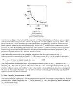
temperature, wind velocity, etc.). The performance of different collector types and applications are shown in Figure 12. The
efficiencies are given for the values: temperature difference between the collector and ambient divided by the solar radiation.
Logically, as the collector gets hotter, the efficiency falls off. For heating of high-performance houses, selective coated collectors or
vacuum pipe collectors are a good choice.
3.12.2.2.3
Integration of solar collectors
It is beneficial to integrate solar collectors into the building envelope for esthetic and economical reasons, and when doing so,
it is essential to take into consideration the architectural rules and local building traditions. Building-integrated collectors are
illustrated in Figure 13. Facade collectors are used in urban buildings, where sufficient suitable and oriented roof for the
installation of solar collectors is not available. A collector element directly integrated in the facade presents both solar
collection and heat insulation of the building envelope. The advantages of facade-integrated collectors are cost savings as a
result of joint use of building components, replacement of the conventional facade, and the collectors suitable for both new
and existing buildings.
Solar Hot Water Heating Systems
431
Efficiency of collector-types and applications
90
80
Unglaced plastic absorber
Flat-plate collector
Flat-plate selective collector
Evacuated-tube collector
Swimming pool
70
Hot water
Efficiency, %
60
Space heat
50
Process heat
40
30
20
10
Tk: collector working temperature, (°C)
Tu: ambient temperature, (°C)
–2
G: solar irradiation, (W m )
0
0
0.05
0.10
0.15
0.20
0.25
0.30
0.35
0.40
0.45
0.50
(Tk – Tu) / G, W, m−2 K−1
Figure 12 Efficiencies of different collector types under different conditions and appropriate uses. Tk, Collector working temperature (°C); Tu, ambient
temperature (°C); G, solar irradiation (W m−2).
For roof installations, where the systems deliver heat over the whole year, the optimal tilt angle (northern hemisphere) is
between 30° and 75°. The orientation can be between 30° east and 45° west. Facade-integrated collector is far from optimum in all
locations (see Section 3.12.3.3). However, it performs better in winter by low sun angles. When there is snow cover, it receives an
extra portion of ground-reflected solar radiation. Roof collectors with too little slope, by contrast, will have zero output when
covered by snow. A big limitation of facade collectors is, however, that by low sun angles, neighboring buildings and trees will cast
shadows on the collector surface.
3.12.2.2.4
New developments in the collector sector
The objective of new developments in the collector sector is the cost reduction as well as durability and reliability of novel
design of solar thermal systems. Polymer engineering and science offers great potential for new products and applications,
which simultaneously fulfill the technological and environmental objectives as well as social needs. The full potential of
polymeric materials can only be used when several product functions are integrated into a single component in a
fundamentally new design. These goals will be achieved by either less expensive materials or less expensive manufacturing
processes.
The most common nowadays is the use of copper absorbers for flat-plate solar collectors. The copper content in conventional
flat-plate collectors varies between 2 and 6 kg m−2. Taking into account the copper used in piping and heat exchangers/heat stores,
5 kg m−2 collector may be a good estimate. Each square meter of collector delivers about 300 kWh heat per year. Hence, 1 MWh per
year corresponds to 16.5 kg copper. Thus, to increase the annual world production of solar heat to 1% of the present human energy
consumption, an installation of 22 million tons of copper absorbers is required. The annual production of copper worldwide is
approximately 15 million tons. The need for new materials is obvious. Aluminum, steel, and other metallic materials will be used
more. Polymeric materials have to be considered as an alternative.
The major advantages in using polymeric materials are low material cost in general (there also exist very expensive
high-performance polymers), low weight, and low manufacturing costs. The latter property is perhaps the most important factor
when choosing polymeric materials for a specific application. Using polymers, at least in large-scale production, complex integrated
structures can be manufactured in a single step through, for example, injection molding or extrusion.
The objective of the project ‘Polymeric Materials for Solar Thermal Applications’ (Task 39) of the Solar Heating and Cooling
(SHC) Programme is the assessment of the applicability and the cost-reduction potential by using polymeric materials and
polymer-based novel designs of suitable solar thermal systems and to promote increased confidence in the use of these products
by developing and applying appropriate methods for assessment of durability and reliability.
3.12.2.3
The Collector Circuit
The durability and reliability of solar water collector systems are influenced by the behavior of the collector circuit/loop. The
collector circuit usually has an antifreeze–water mixture as the heat transfer fluid. A heat exchanger is therefore required for heat
transfer to the store. Exceptions are systems that use the drain-back (Figure 14). With drain-back systems, both overheating and
freezing of fluid in the solar collector loop can be protected.
432
Applications
Figure 13 Building-integrated solar collectors: Roof and facade.
The input to the collector should always be as cold as possible, in order to keep its efficiency high. Therefore, the connecting tube
to the collector is mounted at the bottom of the store, where the coldest water is.
For so-called ‘high-flow’ systems with flow rate in the collector circuit of approximately 50 l h−1 m−2 of collector area, the
temperature rise in the collector is on the order of 10 °C. The input into the store for these high-flow systems should be near the
bottom of the store, and the store is heated slowly from the bottom to the top.
For so-called ‘low-flow’ systems with a specific collector flow rate of 10–15 l h−1 m−2 of collector area, the temperature rise in the
collector is on the order of 40–50 °C. The input to the store for low-flow systems should be higher up than that of the high-flow
systems, the best height depending on the flow rate and system design. It can be advantageous to use a stratifying unit to make sure
Solar Hot Water Heating Systems
(a)
433
Evaporation in the
collector
Condensate
To the storage
Poor location
of the check
valve
Check
valve
Pump
From the storage
Good location
of the check valve
Expansion vessel
Heat store
(b)
Heat store
Drain-back tank
Drain-back tank
Figure 14 The collector circuit and drain-back concepts. (a) Arrangement of the components of the primary solar circuit; (b) implementation of the
drain-back concept when the collector and the heat store are at the same level.
that the heat from the collector goes to the right level in the store. Low flow should not, in general, be used with internal heat
exchangers, as these cannot fully use the high-temperature built up in the collector, and the resulting temperature in the store is
much lower as the water in the store gets mixed rapidly. Moderate flows can be used, but in this case, the internal heat exchanger
should have a greater vertical extent than when using high flows.
3.12.2.3.1
Drain-back system
In ‘drain-back systems’, the collector is drained of fluid when it is not in operation (see Figure 14). The heat transfer fluid is removed
from the collector each time the collector pump stops. This method is used for protection from both frost and overheating. Another
method of overheating protection involves keeping the collector circuit pump in operation and dumping heat in the ground or
some other heat sink. Some systems even cool the store at night so that the risk for overheating the next day is reduced. A system
design that can withstand high pressures (up to 9 bar) in the collector circuit enables the fluid to remain in the collector at all times.
However, this approach can lead to rapid deterioration in the glycol and is not to be recommended for systems with stagnation
temperatures over 140 °C.
Drain-back technology provides an interesting alternative for overheating protection of fluid in the solar collector loop and also
prevents the heat transfer fluid from freezing. When the collector circuit is not running, the circulation can operate using plain water
without (antifreeze) additives due to drain-back of the collector fluid. This system concept is based on draining the water from the
tilted collector and outdoor collector pipes using gravitational force and replacing the liquid with air from the top. By replacing water
in the collector with air, ice cannot be formed and damage is, therefore, avoided. The water also drains back if the heat store is fully
434
Applications
charged, thereby avoiding boiling of water and high pressures inside the system. When using polymer materials in the collector circuit,
both stopping the pump in time and a permanent opening in the collector loop to the atmosphere are needed to avoid overpressure.
In comparison with the use of heat transfer fluids, drain-back technology using water features both advantages and
disadvantages.
Following are the advantages of drain-back technology using water:
• Water does not face the aging drawbacks exhibited by collector fluids with additives, such as a change in material properties and
possible corrosion of the collector loop.
• Heat transfer properties of water, that is, both heat capacity and viscosity, are better than those of other heat transfer fluids.
• Water is much cheaper than all other collector fluids and easily available.
• The collector circuit generally does not face high overpressures, possibly leading to additional guarantee for safety.
• The level of maintenance for drain-back systems is lower.
The disadvantages of drain-back systems are as follows:
• less flexibility in the choice of the solar collector and
• special attention for drain-back collector loop design and installation.
The implementation of the drain-back concept in solar heating systems is simple and inexpensive; draining a solar collector requires
special qualities in hydraulic design. The major feature is that all of the water must run down to the level of the drain-back storage
part of the system when the pump stops. This requirement means that every pipe from the top of the solar collector loop to the
drain-back volume must slope downward. When the collector loop is in operation, the drain-back volume is filled with air. This
volume can be part of the heat stored or integrated into the collector side heat exchanger within the store or it can be designed as
external drain-back tank. When the pump in the collector circuit stops, water drains from the collector to the drain-back volume due
to gravity. This process stops when water levels in both pipes are equal or when the collector loop is empty. When complete, the
collector and all outdoor pipes must be fully filled with air.
Drain-back collector circuits can be implemented as closed or open loops to the environment. Closed loops are commonly used
in collector circuits that can withstand pressures up to at least 3 bar, which usually requires metal absorbers and pipes. After some
time, the metal absorbs the oxygen in the circuit and no further corrosion occurs. Open loops are applied in systems with plastic
materials. Pressures higher than the hydrostatic level should be avoided as combination of high temperature and pressure may cause
weeping and may damage the plastic materials. The properties of the collector have to withstand stagnation temperatures with no
fluid (empty) without deterioration, thermal shock when the collector is hot and suddenly fed with cold water, and repeated
thermal cycling.
The conditions for good emptying behavior of collectors in the event of stagnation can be achieved by the simple repositioning
of the check valve in relation to the expansion vessel as shown in Figure 14.
Different implementations of the drain-back systems were analyzed in the framework of IEA-SHC Programme, Task 26 Solar
Combisystems [4].
3.12.2.4
Thermal Storage
A heating system needs thermal storage when there is a mismatch between thermal energy supply and energy demand, for
example, when intermittent energy sources are utilized. The need for thermal storage in solar hot water systems is often
short term. In such instances, water is a very efficient storage medium. Water storages are sensible heat energy
storages with the advantage of being relatively inexpensive, but the energy density is low and decreases during the storage
time [5–7].
3.12.2.4.1
Water storage technology
The ‘hot water tank’ is one of the best known thermal energy storage technologies. The hot water tank serves to bridge sunless
periods in the case of solar hot water and combined heating system, to increase the system efficiency in combination with
cogeneration systems, and to shave the peak in electricity demand and improve the efficiency of electricity supply in the case of
an electrically heated hot water tank.
Water storage tank technology is mature and reliable. Sensible heat storage in water is still unbeaten regarding simplicity
and cost. In refined systems, the inlet–outlet heights in the tank can vary according to the supply and storage temperatures.
Three types of water storage concepts are in the market: (1) bivalent storage, (2) tank-in-tank storage, and (3) stratified storage
(Figure 15).
Thermally stratified water tanks can improve the annual system efficiency by 20% and more.
‘Short-term storage’ for solar hot water systems typically has a storage volume between 1.5 and 2.0 times of the daily hot water
demand. Even with short-term storage, generous insulation of the tank is essential. For short-term and mid-term storages, one- and
two-storage concepts are used (see Section 3.12.3.2).
Solar Hot Water Heating Systems
435
Solar storages for hot water and space heating
Bivalent heat storage
Tank in tank
Stratified storage
Water storage with thermal stratification
Figure 15 Concepts for water storage technology.
‘Mid-term storage’ for solar-combined heating systems and solar-supported district heating should cover the heat demand for
3–5 days. For detached and row single-family low-energy houses, a storage volume of about 800–1500 l will be suitable.
‘Seasonal storage’ is one means to achieve a high annual share of solar heat in northern latitudes. A realistic target to provide a
heat capacity of 6 months in existing housing or 4 months in low-energy housing is provided.
Mid-term and seasonal storages are used in solar heating plants (district heating).
3.12.2.4.2
Advanced heat storage technologies
For a widespread market deployment of solar thermal systems, it is necessary to store heat efficiently for longer periods of time in
order to reach high solar fractions, and therefore efficient and cost-effective compact storage technologies with high heat capacity are
needed. Advanced storage technologies, such as concepts with a phase-change material or with thermochemical materials, are still in
the research and development stage (Figure 16). Latent heat storage uses the principle of the change of phase of a material named
the storage medium. The physical principle of latent storage is a reaction of phase change. The storage capacity of the storage
medium is equal to the phase-change latent heat at the phase-change temperature + sensible heat stored over the whole temperature
range of the process.
Storage systems based on chemical reactions can achieve much higher energy density than storage systems based on sensible heat
or even latent heat, but are not yet commercially viable. The storage systems based on chemical reactions have negligible losses
whereas sensible heat storage system dissipates the stored heat to the environment and needs to be insulated strongly if the storage
period will be long.
3.12.2.5
Decentralized and Centralized Solar Thermal Systems
Solar heating systems may distinguish between a ‘decentralized’ and a ‘centralized’ approach. In a decentralized approach, the
storage and collectors are placed within the individual houses like in an ordinary active solar heating system but of a larger size. In
the centralized concepts, these components are centrally situated, that is, all solar heat is collected in one storage unit, from which
the heat is distributed to the houses.
Figure 17 illustrates the schematics of solar-supported heating plants.
For central solar thermal systems – for example, for apartment housing – the concept of the heat distribution network is of high
importance. For solar-supported heating systems, four- and two-pipe networks are used. Based on experimental data, two-pipe
436
Applications
Seasonal storage for solar heat
Development of new storage materials
•
Sensible heat
≈ 100 MJ m–3
•
Latent heat
≈ 300 – 500 MJ m–3
•
Thermochemical heat
≈ 1000 MJ m–3
Latent heat
335 kJ
1 kg Ice
0 °C
Sensible heat
1 kg Water
0 °C
335 kJ
1 kg Water
80 °C
Temperature T
T2
Latent
Tmelt
T1
Sensible
Solid
Sensible
Melting
liquid
Heat Q
Figure 16 Advanced heat storage technologies in development.
networks have obvious advantages over four-pipe networks when it comes to the plant efficiency and utilization of the solar system.
Two-pipe networks can be operated in combination with decentralized heat exchangers or decentralized boilers in the row houses.
With individual storages, it is possible to operate the network at different temperatures: lower temperature for space heating (about
40 °C) and higher temperature for hot water preparation (about 65–70 °C). Therefore, the heat losses in the network can be reduced
compared to a network with heat exchangers, which is operated on the highest temperature all the time. On the other hand, the
investment costs for decentralized storages are higher than those for heat exchangers.
The major advantage of having a centralized system is the reduced unit costs and heat losses from the storage. In general, a
centralized system may make better use of the economy of scale (unit prices decrease with the size) than a decentralized one.
The solar unit costs decrease sharply up to approximately 100 m2, as can be seen in Figure 18. This translates to lower
kilowatt-hour costs for the solar heat, as illustrated in the example of Austria.
On the other hand, the heat losses in the pipes of the heat distribution net have to be considered. The relatively high losses in small
district heating systems mainly through the pipes in summer are caused by the lower heat consumption during the summer months.
Smaller systems could be found in countries with moderate climate for multifamily housing and heating systems in commu
nities. The aim of such systems is to cover the hot water demand outside the heating season. Larger district heating plants will be
found in Denmark and Sweden.
3.12.2.6
Auxiliary Heat Sources
In DHW compact systems for households, mainly electricity is used as the auxiliary heat source. Otherwise solar hot water systems
are combined with fossil or biomass boilers or heat pumps for space heating, mainly during the heating season. The hot water
preparation outside the heating season should be covered up to 100% by solar. This goal is also for Solar Combisystems, with
combined hot water preparation and space heating. For example, with a combined solar–biomass heating system the contribution
to the heat demand of a building (space heat and hot water) is covered 100% by renewable energy.
Natural gas is mainly used as backup system in gas district heating.
Solar Hot Water Heating Systems
437
Solar supported district heating
Midterm storage
Building
Collectors
Heat station
Auxiliary heating
Collector area
Boiler
Heat distribution net work
Heat storage
Collector pipes
Solar thermal system with central storage in
combination with decentralized
hot water storage tanks
a Energy storage tank
re
a
or
ct
lle
Co
Solar thermal system with central storage in
combination with decentralized heat exchangers
Heating
circuit
Storage
tank
Cool water
Hot water
Storage
tank
Cool water
Hot water
boiler
Two-pipe network
Storage
tank
Cool water
Hot water
Two-pipe network
Figure 17 Schematic diagrams for district heating plants and examples for small district heating in Austria.
3.12.2.7
Hygienic Aspects of Solar Hot Water Heaters
In some active solar system configurations, the storage tank contains drinking water. There is then the risk of the so-called Legionnaires’
disease, Legionella pneumonia. It is caused by Legionella, or rod-shaped, mobile, aerobic bacteria that occur naturally in surface water
and groundwater. They begin to propagate at temperatures between 20 and 50 °C, with optimum growth occurring between 30 and
40 °C. Above 60 °C, they die off quickly. A long residence time in water at favorable temperatures may result in high concentrations of
Legionella. Stagnant water in pipes or in parts of an installation that have not been flushed is a breeding ground for these bacteria.
438
Applications
Collector area and collector costs
Costs for installed collector area
800
Maximal costs
Costs (Euro m–2)
700
Average costs
600
Minimal costs
500
400
300
200
100
Maximal costs:
installation on flat roofs
Minimal costs:
building integrated
0
5
50
100
150
200
250
2
Collector area (m )
300
350
400
Solar hot water system
Heat production costs
Costs (Euro kWh–1)
0,30
Lifetime of solar system
0,25
Annual solar share:
45%–50%
0,20
15 years
20 years
25 years
0,15
30 years
0,10
0,05
0,00
6
10
20
30
40
50
60
70
Collector area (m2)
80
90
100
Figure 18 Economic aspects of solar water heating systems.
To prevent the growth of Legionella, the water temperature should be either below 25 °C or above 50 °C. Disinfecting a
contaminated system can be done by flushing it, then heating the water to 60 °C for 20 min. In general, solar thermal systems
for hot water preparation are backed up by an auxiliary heating system to achieve temperatures above 50 °C. In this manner, the risk
of Legionella-contaminated water can be minimized.
A distinction is made between small and large systems. Small systems are considered to have a very low risk and need no special
attention. Small systems are installations in one- or two-family houses, or installations with volume <400 l and with <3 l in pipes
between the heater outlet and draw-off point. Large systems should be designed so that they can be heated up to 60 °C in a
frequency prescribed by the building/sanitary code.
3.12.3 Design Principles of Solar Thermal Systems
The economic efficiency of solar heating systems depends mainly on its design. Thus, the optimal design of all components of the
system – collector, storage, tanks, pumps, control mechanism, and piping – as well as the design of collector area and storage
volume as a function of the daily/hourly hot water demand is essential.
3.12.3.1
Meteorological Conditions and Simulation Tools
The useful heat output of a collector system depends also on the influencing meteorological quantities at the location, as well as on
the structure of consumption.
Meteorological data from all parts of the world are used to simulate solar energy systems. For many regions, the measured
data may only be applied within a 50 km radius of the collection station. This makes it necessary to interpolate parameters
between stations. Through existing data sets, for example, Meteonorm, it is possible to simulate solar energy systems in all
parts of the world on a consistent basis. The interpolation errors are within the variations of climate from 1 year to the
next [8].
Figure 19 shows the annual global solar radiation, and Figure 20 shows the absorbed solar radiation on tilted surface for
different orientations and tilt angles for south-facing collectors in three climates.
There are several computer programs (simulation tools) in the market for the thermal performance calculation of solar heating
systems: for example, Polysun, TSOL, and SHWwin [9–11]. All are transient simulation programs with time steps of a few minutes
and feature database support for components and systems. The assurance of results from simulations is depending from the input
data, also considering the site conditions, the system design, and the application, for example, required heat demand. Proved
simulation tools will allow the pre-design of solar thermal systems in an easy and short way. For simple hot water systems –
compact systems – no extra simulation work will be necessary. For more complicated systems – hot water systems for apartment
housing, settlements, commercial buildings, as well as Solar Combisystems – additional detailed simulation is recommended, in
combination with a sensibility analysis: ‘energy-economic design’.
Solar Hot Water Heating Systems
439
0
80
0
80
1100
1100
1950
0
220
1400
1400
1700
1100
1400
170
0
1950
1400
2200
2200
50
19
1700
1950
1700
1700
0
195
22
00
50
0
170
00
1950
1700
19
1700
22
1100
00
1700
1400
1400
1950
22
1400
1100
1100
800
640–900
900–1050
1050–1200
1200–1360
1360–1600
1600–1700
1700–1900
1900–2100
2100–2300
>2300
nonstudy
area
METEONORM 4.0
Global irradation: year (kWh m–2)
70
60
50
40
30
20
10
0
–10
–20
–30
–40
–50
–60
–70
–180 –170 –160 –150 –140 –130 –120 –110 –100 –90 –80 –70 –60 –50 –40 –30 –20 –10
−2
0
10
20
30
40
50
60
70
80
90 100 110 120 130 140 150 160 170 180
−1
Figure 19 Global annual solar radiation (kWh m yr ).
The main influencing factors to the output – heat production on daily, monthly, and annual basis – are the following:
• Meteorological conditions on site: availability of absorbed solar radiation on collector area (shading, dust, and snow on collector
surface) and ground reflection of solar radiation (albedo).
440
Applications
Solar irradiation on tilted surface
Influence of collector orientation
Absorbed solar irradiation (%)
100
95
90
Stockholm
Zurich
Milan
85
80
75
Collector inclination: 45°
South: 0°, West/east: 90°
70
0
30
45
60
90
Collector orientation (degree)
Absorbed solar irradiation
kWh m–2 yr–1
Solar irradiation on tilted surface
influence of collector inclination
1.400
1.350
1.300
1.250
1.200
1.150
1.100
1.050
1.000
950
900
850
800
750
Stockholm
Zurich
Milan
Collector azimuth: 0° (South)
optimal inclination
Horizontal: 0°, Vertical: 90°
0
30
45
60
90
Collector inclination, degree
Figure 20 Solar radiation for different orientations and tilt angles for south-facing collectors in three climates.
• Heat demand: day profiles on hourly basis, week profiles on daily basis, and month profiles on weekly basis.
• Water temperature: collector inlet and outlet temperatures.
• Collector: collector characteristics (conversion factor and heat loss coefficient), depending on type and product, and connection
of collectors.
• Collector loop: pipes’ length and diameter, insulation, heat exchanger, high-flow systems, low-flow systems, and drain-back
systems (protection from both overheating and freezing of fluid in the solar collector loop).
• Collector size, inclination, and orientation.
• Storage: amount of stores, volume, and combination of two and more stores; height and length; insulation; loading and
discharging strategy; and ambient temperature.
• System integration, including regulation.
Figure 21 illustrates the program structure of simulation tools.
SHWwin is used for the following simulations.
3.12.3.2
The Solar System
For the system efficiency, the ‘heat management philosophy’ is important: priority is given to the load (DHW or space heating) with
the lowest temperature level, so that the solar collector works with the highest efficiency. Thus, the implementation of thermal
storage in a solar system and its volume, depending on storage capacity and the application, is of great importance for the efficiency
and the solar share of a heating system.
The storage concept comprises the strategies – which are adjusted to the particular design of the collector area – for loading and
discharging as well as for additional heating (Figure 22). Typical and practically proved storage concepts for solar thermal systems
are ‘one-storage’ and ‘multistorage’ systems adjusted to loading and discharging strategies with collector characteristics and the heat
demand. Thermally stratified water tank represents an ideal thermal storage: The inlet–outlet levels can be changed and may be
considered as an advanced solar system for DHW and space heating concept. This type of storage will improve the annual solar
system efficiency by about 20% and more.
Solar Hot Water Heating Systems
Monthly weather data
441
System input data
global horizontal radiation,
direct and diffuse radiation,
ambient temperature
thermal and
economic data
Weather simulation
System simulation
Default weather
input files
Default system
input files
System output data
Solar system heat output
Solar share/month
(%)
Solar hot water system
solar heat output
Solar heat
(kWh per month)
100
90
350
80
300
70
60
250
Annual Solar Share:
60.6%
50
200
Annual heat output:
40
150
30
100
20
50
10
0
0
1
2
3
4
5
Stockholm
6
7
Month
8
Zurich
9
10
11
Milan
12
1
2
3
4
5
6
7
Month
Solar heat
8
9
10
11
12
Auxiliary heat
Figure 21 Program structure of simulation tools.
Two-storage solar DHW systems are typically used in apartment houses and Solar Combisystems: buffer store and separate hot
water store.
To reduce the heat losses of the heat distribution system in larger buildings with more consumers, a combination of buffer
storage and decentralized stores as well as decentralized heat exchangers may be a more efficient and cost-effective solution
(see Figure 17).
Summarizing, the ‘one-storage concept’ will be the best solution for solar DHW systems for households and single-family
houses, the ‘multistorage concept’ for apartment houses, and the ‘two-storage concept’ as well as the ‘stratified storage concept’ for
combined hot water and space heating systems.
3.12.3.3
Collector Orientation and Inclination
The design of a solar heating system has to consider the meteorological conditions on site.
The intensity of the solar radiation on a flat surface is higher when it is titled toward the sun. The maximum intensity
occurs when the flat surface is perpendicular to the sun’s rays. Two-axis tracking of absorbers may thus maximize the energy
gain at the expense of technical complexity. For fixed absorber surfaces, the energy gain is a function of the slope angle
(0° = horizontal, 90° = vertical) and the azimuth angle (0° = south, –90° = east, +90° = west, and 180° = north). The
distribution of the annual incident energy on a tilted surface as a function of slope and azimuth angle has to be considered
within the installation as well as integration of solar thermal collectors in building envelope. The absorbed solar
radiation on tilted surface is shown in Figure 20 for different orientations and tilt angles for south-facing collectors in
three climates.
Collector orientation is best between 30° east and 45° west. Compared with tilted collector areas, the absorbed solar radiation
on facade collectors is reduced by about 25–30% as an average. The difference during the heating season is smaller. From the
energetic point of view, facade-integrated collectors are acceptable in solar-combined heating systems with an oversized collector
area for hot water preparation outside the heating season.
Nevertheless, the distribution of the annual incident energy on a tilted surface gives some freedom on choosing acceptable
surfaces for collection of solar energy.
442
Applications
Two-storage system
(with priority for loading)
One-storage system
Solar
collectors
Solar
collectors
Additional
heating
Additional
heating
Hot water
Additional
heating
Heat
storage
Hot water
tank
Heat
load
Heat
excharger
Buffer
storage
Space heating
Heat
excharger
One-storage system with thermal stratification
for loading and discharging through different layers
Multistorage system
Heat load
Solar
collectors
Solar
collectors
Heat
excharger
One-storage solar system
for hot water preparation
Two-storage solar system
with buffer and hot water storage
ea
Tank in tank system
Energy storage tank
ar
ea
ct
or
ar
Stand-by storage
tank
Hot water
Co
lle
Hot water
c
lle
o
C
Heat load
Heat
storage
Heat
exchanger
r
to
Additional
heating
Heat
storage n
Heat
storage 2
Heat
storage 1
Additional
heating
WMZ 3
Circulation
pipe
Heating
circuit
Cold water
WMZ 2
WMZ 1
Cold
water
WMZ 4
WMZ 5
WMZ... Energy amout meter
Circulation
pipe
Figure 22 Hydraulic principle schematics for solar heating systems.
For roof installations, where the systems deliver heat over the whole year, the optimal tilt angle (northern hemisphere) is
between 30° and 75°. The orientation can be between 30° east and 45° west. As can be seen, a 90° tilt, or facade-integrated
collector, is far from optimum in all locations.
3.12.3.4
Solar DHW Systems for Households and Single-Family Houses
In solar systems for hot water preparation, flat-plate collectors of different designs (nonevacuated- and evacuated-tube collectors
with and without selective coating) are used. Flat-plate collectors with selective coating – today the standard – may be in many cases
the most cost-effective solution. For higher temperatures (above 80 °C), evacuated-tube collectors would be more successful.
Solar hot water preparation is nearly similar in all climates during the summer period. Figure 23 illustrates the global radiation
and the heat output of solar DHW systems for households in the three reference climates: cold (Stockholm), temperate (Zurich),
and mild (Milan). The difference in the annual solar heat output between cold and mild climates amounts to 14%. The influence of
collector type, collector inclination and orientation, collector size, and storage volume to the annual solar share is illustrated in
Figure 23.
The design of a solar hot water system should be oriented on the hot water demand outside the heating season. Under the typical
meteorological conditions in temperate climates, the annual solar share for hot water preparation – considering also economical
443
Solar Hot Water Heating Systems
Monthly global irradiation on horizontal surface
Solar system for household
Collector area: 8 m2
Solar hot water system
Solar heat output
Cold (Stockholm), temperate (Zurich) and mild (Milan) climate
200
(selective flat plate)
350
Storage volume: 500 l
180
Solar heat (kWh per month)
160
140
120
100
80
Annual Global Irradiation
60
Stockholm: 980
Zurich: 1104
Milan: 1251
40
20
0
1
2
3
4
5
6
7
Month
Stockholm
8
9
10
Zurich
11
12
120 l day–1 (50 °C)
300
250
200
Annual heat output
(kWh a–1)
150
100
Stockholm: 2370
Zurich: 2569
Milan: 2753
50
0
1
2
3
Milan
4
5
6
7
Month
Stockholm
8
9
10
Zurich
11
12
Milan
Solar system for hot water
Solar system for hot water
Compact system for household
Compact system for household
80
74
75
66
80
90
80
70
60
60
50
40
Selective
flat plate collector
30
Evacuated
collector
20
Azimuth: 0° (south),
10
Inclination: 45°
120 l day–1 (50 °C)
85
80
68
61
70
73
79
74
67
50
40
30
20
10
0
0
Collector area/storage volume
Collector area/storage volume
Stockholm
Zurich
Stockholm
Milan
Zurich
Milan
Solar hot water system
Compact system for household, 120 l day–1 (50 °C), Zurich
Solar system for hot water
Solar share (%)
100
Compact System for Household
75
Selective flat
plate collector
80
70
60
50
40
30
20
10
0
90
80
80
66
61
57
70
67
60
Annual Solar Share:
74.8%
50
40
30
20
10
0
1
45°
Inclination
Stockholm
2
3
Zurich
Milan
4
5
6
7
8
9
10
11
12
Month
90° (vertical)
Storage volume:
500 l
Solar heat
Auxiliary heat
Figure 23 Design of solar domestic hot water (DHW) system for a household in three reference climates.
aspects and in dependence on the daily hot water demand – should be in the range of about 60–70%, and during the summer
period, the solar share would be about 70–90%.
Facade collectors reduce the annual solar share by 5% (cold climate), 18% (temperate climate), and 13% (mild climate),
compared with roof-integrated collector (45°).
For the economy and energy efficiency, the tank should be from 1.5 to 2.0 times greater than the daily hot water demand, and the
collector area between 1 and 2 m2 per occupant. Typically, designs for solar hot water systems in households are 3 m2 per 300 l for
up to three persons and 8 m2 per 500 l for four to five persons.
3.12.3.5
Solar DHW Systems for Apartment Houses
The influence of collector type, storage size, and collector orientation is illustrated in Figure 24. Also, the monthly solar share
of a solar DHW system for an apartment block, 96 m2 of flat-plate collector supplying a 4000 l storage tank in moderate
climate (demand 1920 l day−1 at 50 °C), is shown [5]. In apartment houses, the annual solar share for hot water preparation
will generally be below 50% due to lack of space on the roof for the installation of collectors. The use of solar hot water
systems in an apartment house has the advantage of lower specific investment costs, and thus, the heat production costs can be
reduced in comparison with small, decentralized systems. The possibilities for a central hot water preparation in apartment
houses are used increasingly in the market nowadays. Surprisingly, within a large range, the size of the tank relative to the
collector area is not a major factor affecting system performance. This is evident in the example of an apartment block shown
in Figure 24. Doubling the tank size increases the solar share by <15%. More important is avoiding the mixing of the hot water
at the top of the tank with cooler water at the bottom, the insulation of the tank, and the avoidance of thermal bridges, for