SF1E Shinko Techno DFT700M Nhiệt kế hồng ngoại IRT500TE THIẾT BỊ ĐIỆN CÔNG NGHIỆP ĐIỆN TỰ ĐỘNG HÓA ĐO LƯỜNG ĐIỀU KHIỂN
Bạn đang xem bản rút gọn của tài liệu. Xem và tải ngay bản đầy đủ của tài liệu tại đây (210.7 KB, 2 trang )
SF SERIES
SPEC. SHEET
1ch Thermocouple Transmitter
Model
SF1E -
-
Input
(Burnout: Upscale)
01: K
02: J
03: R
04: S
05: B
06: E
07: T
08: N
09: PL-II
10: W5Re/W26Re
11: W3Re/W25Re
(Burnout: Downscale)
21: K
22: J
23: R
24: S
25: B
26: E
27: T
28: N
29: PL-II
30: W5Re/W26Re
31: W3Re/W25Re
Input sampling period
01: 25ms
02: 125ms
03: 250ms
Output
01: 4 to 20mA DC 06: 0 to 1V DC
02: 0 to 20mA DC 07: 0 to 5V DC
03: 0 to 12mA DC 08: 1 to 5V DC
04: 0 to 10mA DC 09: 0 to 10V DC
05: 1 to 5mA DC
Socket
1: Screw fall prevention, finger-safe
(For Y terminal)
2: For Ring terminal
Power supply
0: 100 to 240V AC
1: 24V AC/DC
How to Order
Specify a model and input range.
(e.g.) SF1E-010101-1-0
Default value
Input
K -200 to 1370
Output
4 to 20mA DC
Input sampling period
25ms
Input Specifications
Thermocouple
Input resistance: 1M or more
External resistance: 100 or less, however,
B: 40 or less
Burnout: Upscale/Downscale
Model:
SF1E
-
Input:
Thermocouple
Input Range
K
-200 to 1370
-328 to 2498
J
-200 to 1000
-328 to 1832
R
-50 to 1760
-58 to 3200
S
-50 to 1760
-58 to 3200
B
0 to 1820
32 to 3308
E
-200 to 800
-328 to 1472
T
-200 to 400
-328 to 752
N
-200 to 1300
-328 to 2372
PL-
0 to 1390
32 to 2534
W5Re/W26Re
0 to 2315
32 to 4199
W3Re/W25Re
0 to 2315
32 to 4199
Minimum span: 50
(100 )
Output Specifications
DC Current
Output
range
Allowable
load
resistance
Zero
adjustment
range
Span
adjustment
range
4 to 20mA DC
700
or less
-5 to 5%
95 to 105%
0 to 20mA DC
700
or less
0 to 5%
95 to 105%
0 to 12mA DC
1.2k
or less
0 to 5%
95 to 105%
0 to 10mA DC
1.2k
or less
0 to 5%
95 to 105%
1 to 5mA DC
2.4k
or less
-5 to 5%
95 to 105%
Zero
adjustment
range
Span
adjustment
range
0 to 5%
0 to 5%
-5 to 5%
0 to 5%
95 to 105%
95 to 105%
95 to 105%
95 to 105%
DC Voltage
Output
range
0 to 1V DC
0 to 5V DC
1 to 5V DC
0 to 10V DC
Allowable
load
resistance
100
or more
500
or more
500
1k
or more
or more
SF1E
Performance
Power consumption: Approx. 6VA
Ambient temperature: -5 to 55
Ambient humidity: 35 to 85%RH (non-condensing)
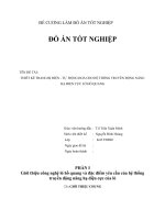
Weight: Approx. 190g (including socket)
Mounting: DIN rail
Dimensions: W30 x H88 x D108mm (including socket)
Accuracy: Within 0.2% of input span (at 23 of
ambient temperature)
R, S input, -50 to 200 (-58 to 392 ): Within 8 (16 )
B input, 0 to 300 (32 to 572 ): Accuracy is not
guaranteed.
K, J, E, T, N input, Less than 0 (32 ): Within 0.5% of
input span
Cold junction compensation accuracy: Within 1 at
-5 to 55
Input sampling period: 25ms, 125ms, 250ms
(Must be specified)
Response time:
65ms (typ.)(0→90%)(Input sampling period: 25ms)
225ms (typ.)(0→90%)(Input sampling period: 125ms)
425ms (typ.)(0→90%)(Input sampling period: 250ms)
Temperature coefficient: 0.015%/ or less
Insulation resistance: 10M or more, at 500V DC
(Input - Output - Power)
Dielectric strength: 2.0kV AC for 1 minute
(Input - Output - Power)
Attached Functions
Power failure countermeasure:
The data is backed up in non-volatile IC memory.
Self diagnosis:
The CPU is monitored by a watchdog timer, and when
an abnormal status is found on the CPU, the unit is
switched to warm-up status turning all outputs OFF.
Cold junction compensation: Available
Environmental Specifications
RoHS directive compliance
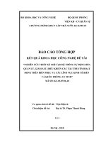
Settings
Function keys
(1) UP Key: Increases a numerical value.
(2) DOWN Key: Decreases a numerical value.
(3) MODE Key: Switches from RUN mode to
the Adjustment mode, and
registers the adjustment value.
General Structure
Case: Flame-resistant resin
Color: Light gray
Front panel: Membrane sheet
Adjustment: Using the front keypad
(1) Press the MODE Key. The ZERO indicator becomes
lit. The unit moves to the Output ZERO adjustment mode.
(2) Press the MODE Key in the Output ZERO adjustment mode. The SPAN indicator becomes lit.
The unit moves to the Output SPAN adjustment mode.
(3) Pressing the MODE Key returns to Step (1).
If the MODE Key is pressed for approx 3 sec, or if no
operation occurs for approx. 30 sec, the unit will
revert to the RUN mode.
Indication:
PWR indicator (Green):
Lit when power is turned ON.
Flashes in 0.5 second cycles if non-volatile memory
errors occur.
Flashes in 0.25 second cycles if input errors occur.
ZERO indicator (Yellow):
Lit in the Output ZERO adjustment mode.
SPAN indicator (Yellow):
Lit in the Output SPAN adjustment mode.
ZERO Indicator
Power
Indicator
SPAN Indicator
Solderless Terminals
Y Terminal
Ring Terminal
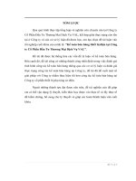
Circuit Configuration, Terminal Arrangement
TC
Input
+1
-
2
3
Input
circuit
Indicator/
Setting key
circuit
13
Output
circuit
9
14
+
-
Power
supply
Insulation circuit
4
CPU
5
Power
circuit
+
Output
10
-
6
7
8
11
12
External Dimensions (Scale: mm)
UP Key
MODE Key
DOWN Key
Installation Specifications
Power supply: 100 to 240V AC 50/60Hz
24V AC/DC 50/60Hz
Allowable voltage range: 85 to 264V AC
20 to 28V AC/DC
SHINKO TECHNOS CO., LTD.
Tel: +81-72-727-6100
URL: E-mail:
20111125