SBP Shinko Techno DFT700M Nhiệt kế hồng ngoại IRT500TE THIẾT BỊ ĐIỆN CÔNG NGHIỆP ĐIỆN TỰ ĐỘNG HÓA ĐO LƯỜNG ĐIỀU KHIỂN
Bạn đang xem bản rút gọn của tài liệu. Xem và tải ngay bản đầy đủ của tài liệu tại đây (181.75 KB, 2 trang )
SB series
SPEC. SHEET
Potentiometer Transmitter
Model:
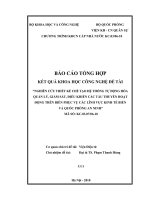
SBP
Features
Simple wiring using a plug-in socket
Compact
3-port insulation (Input-Output-Power)
Model
SBP–□□–□
Input signal
01: Total resistance 100
Output signal
01: 4 to 20mA DC
02: 0 to 20mA DC
03: 0 to 12mA DC
04: 0 to 10mA DC
to 10k
05: 0 to 1V DC
06: 0 to 5V DC
07: 1 to 5V DC
08: 0 to 10V DC
Performance
Power supply
0: 100 to 240V AC
1: 24V DC
Accuracy
Response time
: Within 0.2%
: 1 sec. (0
90%)
(Average 0.5 sec)
Temperature coefficient: 0.015%/
Insulation resistance : 10M or more, at 500V DC
(Input-Output-Power)
Dielectric strength
: 2.0kV AC for 1 minute
(Input-Output-Power)
How to order
Specify a model name.
(e.g.) SBP-0101-0
General specifications
Input specifications
Total resistance : 100 to 10k
Reference voltage: 1.0V DC
Minimum span
: 50% or more of the Total resistance
Output specifications
When the output range lower limit is zero, (even if zero
adjustment results in a negative value), output value will
not indicate a negative value.
DC current
Output range
4 to 20mA DC
0 to 20mA DC
0 to 12mA DC
0 to 10mA DC
Allowable load
resistance
600 or less
600 or less
1k or less
1k or less
DC voltage
Output range
0 to 1V DC
0 to 5V DC
1 to 5V DC
0 to 10V DC
Allowable load
resistance
100 or more
500 or more
500 or more
1k or more
Case
: Flame resistant resin, Color: Light gray
Panel
: Polycarbonate
Spring type plug : Polyamide, Color: Green
Adjustment
: By the front adjustment button
Zero adjustment:
By pressing the Zero adjustment button for 2 seconds
after setting the input potentiometer to any position of
the MIN side, zero position is automatically registered.
Span adjustment:
By pressing the Span adjustment button for 2 seconds
after setting the input potentiometer to any position of
the MAX side, span position is automatically registered.
Indication:
PWR indicator: Green
Lights when power is turned on.
Flashes in 500ms cycles when an error has occurred
in non-volatile memory.
ERR indicator: Red
Flashes in 250ms cycles when input is 110% or more.
Flashes in 500ms cycles when input is -10% or less.
Output status selection:
Output status either Normal or Reverse can be selected
by the DIP switch.
No.1 OFF: Normal, ON: Reverse
Momentary power failure: 30msec
Self diagnosis:
The CPU is monitored by a watchdog timer, and when
an abnormal status is found on the CPU, the unit
restarts with the Reset action.
SBP
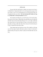
Circuit configuration, terminal arrangement
Power indicator
Zero adjustment
Error indicator
Span adjustment
Power supply
Output
+
+
+
6
Power
circuit
5
Output
circuit
Output
-
+
4
3
Potentiometer
Input
7
Power supply
MIN
.
2
MIN
MAX
MAX
.
1
Input
circuit
CPU
Reference
voltage
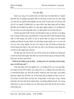
External dimensions (Scale: mm)
DIP switch
DIN rail
Spring type plug
Installation specifications
Power supply
• 100 to 240V AC 50/60Hz
Allowable voltage range: 85 to 264V AC
Power consumption
: Approx. 3.5VA
• 24V DC
Allowable voltage range: 20 to 28V DC
Power consumption
: Approx. 3.5W
Ambient temperature : -5 to 55
Ambient humidity
: 35 to 85%RH (non-condensing)
Weight
: Approx. 80g
Mounting method
: DIN rail mounting
Be sure to use fastening plates at
both ends of the unit after the unit
is mounted to the DIN rail.
External dimensions : 17.5 (W) x 75 (H) x 85 (D) mm
Environmental specification
RoHS directive compliance
Ferrules
Made by Phoenix Contact GMBH & CO.
Insulation sleeve attached
Model
Conductor cross section
2
AI0.25-6BU
0.2 – 0.25mm
2
AI0.34-8TQ
0.25 – 0.34mm
2
AI0.5-8WH
0.34 – 0.5mm
2
AI0.75-8GY
0.5 – 0.75mm
2
AI1-8RD
0.75 – 1.0mm
2
AI1.5-8BK
1.0 – 1.5mm
2
AI2.5-8BU
1.5 – 2.5mm
Crimping pliers
CRIMPFOX ZA3
CRIMPFOX UD6
SHINKO TECHNOS CO., LTD.
Tel: +81-72-727-6100
URL: />E-mail:
20100624