Solution manual heat and mass transfer a practical approach 3rd edition cengel CH01
Bạn đang xem bản rút gọn của tài liệu. Xem và tải ngay bản đầy đủ của tài liệu tại đây (198.48 KB, 17 trang )
1-1
Chapter 1
INTRODUCTION AND BASIC CONCEPTS
Thermodynamics and Heat Transfer
1-1C Thermodynamics deals with the amount of heat transfer as a system undergoes a process from one
equilibrium state to another. Heat transfer, on the other hand, deals with the rate of heat transfer as well as
the temperature distribution within the system at a specified time.
1-2C (a) The driving force for heat transfer is the temperature difference. (b) The driving force for electric
current flow is the electric potential difference (voltage). (a) The driving force for fluid flow is the pressure
difference.
1-3C The caloric theory is based on the assumption that heat is a fluid-like substance called the "caloric"
which is a massless, colorless, odorless substance. It was abandoned in the middle of the nineteenth
century after it was shown that there is no such thing as the caloric.
1-4C The rating problems deal with the determination of the heat transfer rate for an existing system at a
specified temperature difference. The sizing problems deal with the determination of the size of a system
in order to transfer heat at a specified rate for a specified temperature difference.
1-5C The experimental approach (testing and taking measurements) has the advantage of dealing with the
actual physical system, and getting a physical value within the limits of experimental error. However, this
approach is expensive, time consuming, and often impractical. The analytical approach (analysis or
calculations) has the advantage that it is fast and inexpensive, but the results obtained are subject to the
accuracy of the assumptions and idealizations made in the analysis.
1-6C Modeling makes it possible to predict the course of an event before it actually occurs, or to study
various aspects of an event mathematically without actually running expensive and time-consuming
experiments. When preparing a mathematical model, all the variables that affect the phenomena are
identified, reasonable assumptions and approximations are made, and the interdependence of these
variables are studied. The relevant physical laws and principles are invoked, and the problem is formulated
mathematically. Finally, the problem is solved using an appropriate approach, and the results are
interpreted.
1-7C The right choice between a crude and complex model is usually the simplest model which yields
adequate results. Preparing very accurate but complex models is not necessarily a better choice since such
models are not much use to an analyst if they are very difficult and time consuming to solve. At the
minimum, the model should reflect the essential features of the physical problem it represents.
PROPRIETARY MATERIAL. © 2007 The McGraw-Hill Companies, Inc. Limited distribution permitted only to teachers and
educators for course preparation. If you are a student using this Manual, you are using it without permission.
1-2
Heat and Other Forms of Energy
1-8C The rate of heat transfer per unit surface area is called heat flux q& . It is related to the rate of heat
transfer by Q& =
∫ q&dA .
A
1-9C Energy can be transferred by heat, work, and mass. An energy transfer is heat transfer when its
driving force is temperature difference.
1-10C Thermal energy is the sensible and latent forms of internal energy, and it is referred to as heat in
daily life.
1-11C For the constant pressure case. This is because the heat transfer to an ideal gas is mcpΔT at constant
pressure and mcvΔT at constant volume, and cp is always greater than cv.
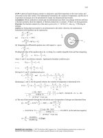
1-12 A cylindrical resistor on a circuit board dissipates 0.8 W of power. The amount of heat dissipated in
24 h, the heat flux, and the fraction of heat dissipated from the top and bottom surfaces are to be
determined.
Assumptions Heat is transferred uniformly from all surfaces.
Analysis (a) The amount of heat this resistor dissipates during a 24-hour period is
Q = Q& Δt = (0.8 W)(24 h) = 19.2 Wh = 69.1 kJ (since 1 Wh = 3600 Ws = 3.6 kJ)
(b) The heat flux on the surface of the resistor is
As = 2
q& s =
πD 2
4
+ πDL = 2
π (0.4 cm) 2
4
+ π (0.4 cm)(2 cm) = 0.251 + 2.513 = 2.764 cm 2
Q&
Resistor
0.8 W
Q&
0.80 W
=
= 0.289 W/cm 2
As 2.764 cm 2
(c) Assuming the heat transfer coefficient to be uniform, heat transfer is proportional to the
surface area. Then the fraction of heat dissipated from the top and bottom surfaces of the
resistor becomes
Q top − base
Q total
=
Atop − base
Atotal
=
0.251
= 0.091 or (9.1%)
2.764
Discussion Heat transfer from the top and bottom surfaces is small relative to that transferred from the side
surface.
PROPRIETARY MATERIAL. © 2007 The McGraw-Hill Companies, Inc. Limited distribution permitted only to teachers and
educators for course preparation. If you are a student using this Manual, you are using it without permission.
1-3
1-13E A logic chip in a computer dissipates 3 W of power. The amount heat dissipated in 8 h and the heat
flux on the surface of the chip are to be determined.
Assumptions Heat transfer from the surface is uniform.
Analysis (a) The amount of heat the chip
dissipates during an 8-hour period is
Logic chip
Q& = 3 W
Q = Q& Δt = (3 W)(8 h ) = 24 Wh = 0.024 kWh
(b) The heat flux on the surface of the chip is
Q&
3W
= 37.5 W/in 2
q& = =
A 0.08 in 2
1-14 The filament of a 150 W incandescent lamp is 5 cm long and has a diameter of 0.5 mm. The heat flux
on the surface of the filament, the heat flux on the surface of the glass bulb, and the annual electricity cost
of the bulb are to be determined.
Assumptions Heat transfer from the surface of the filament and the bulb of the lamp is uniform.
Analysis (a) The heat transfer surface area and the heat flux on the surface of the filament are
As = πDL = π (0.05 cm)(5 cm) = 0.785 cm 2
Q&
150 W
=
= 191 W/cm 2 = 1.91× 10 6 W/m 2
q& s =
As 0.785 cm 2
Q&
Lamp
150 W
(b) The heat flux on the surface of glass bulb is
As = πD 2 = π (8 cm) 2 = 201.1 cm 2
q& s =
Q&
150 W
=
= 0.75 W/cm 2 = 7500 W/m 2
As 201.1 cm 2
(c) The amount and cost of electrical energy consumed during a one-year period is
Electricity Consumptio n = Q& Δt = (0.15 kW)(365 × 8 h/yr) = 438 kWh/yr
Annual Cost = (438 kWh/yr)($0.08 / kWh) = $35.04/yr
PROPRIETARY MATERIAL. © 2007 The McGraw-Hill Companies, Inc. Limited distribution permitted only to teachers and
educators for course preparation. If you are a student using this Manual, you are using it without permission.
1-4
1-15 A 1200 W iron is left on the ironing board with its base exposed to the air. The amount of heat the
iron dissipates in 2 h, the heat flux on the surface of the iron base, and the cost of the electricity are to be
determined.
Assumptions Heat transfer from the surface is uniform.
Analysis (a) The amount of heat the iron dissipates during a 2-h period is
Iron
1200 W
Q = Q& Δt = (1.2 kW)(2 h) = 2.4 kWh
(b) The heat flux on the surface of the iron base is
Q& base = (0.85)(1200 W) = 1020 W
q& =
Q& base
1020 W
=
= 68,000 W/m 2
Abase 0.015 m 2
(c) The cost of electricity consumed during this period is
Cost of electricity = (2.4 kWh) × ($0.07 / kWh) = $0.17
1-16 A 15 cm × 20 cm circuit board houses 120 closely spaced 0.12 W logic chips. The amount of heat
dissipated in 10 h and the heat flux on the surface of the circuit board are to be determined.
Assumptions 1 Heat transfer from the back surface of the board is negligible. 2 Heat transfer from the front
surface is uniform.
Analysis (a) The amount of heat this circuit board
dissipates during a 10-h period is
Chips,
0.12 W
Q& = (120)(0.12 W) = 14.4 W
Q&
Q = Q& Δt = (0.0144 kW)(10 h) = 0.144 kWh
(b) The heat flux on the surface of the circuit board is
15 cm
As = (0.15 m)(0.2 m) = 0.03 m 2
q& s =
Q&
14.4 W
=
= 480 W/m 2
As 0.03 m 2
20 cm
PROPRIETARY MATERIAL. © 2007 The McGraw-Hill Companies, Inc. Limited distribution permitted only to teachers and
educators for course preparation. If you are a student using this Manual, you are using it without permission.
1-5
1-17 An aluminum ball is to be heated from 80°C to 200°C. The amount of heat that needs to be
transferred to the aluminum ball is to be determined.
Assumptions The properties of the aluminum ball are constant.
Properties The average density and specific heat of aluminum are
given to be ρ = 2700 kg/m3 and cp = 0.90 kJ/kg⋅°C.
Metal
ball
Analysis The amount of energy added to the ball is simply the change in its
internal energy, and is determined from
E transfer = ΔU = mc p (T2 − T1 )
where
E
m = ρV =
π
6
ρD 3 =
π
6
( 2700 kg/m 3 )(0.15 m) 3 = 4.77 kg
Substituting,
E transfer = (4.77 kg)(0.90 kJ/kg ⋅ °C)(200 − 80)°C = 515 kJ
Therefore, 515 kJ of energy (heat or work such as electrical energy) needs to be transferred to the
aluminum ball to heat it to 200°C.
1-18 The body temperature of a man rises from 37°C to 39°C during strenuous exercise. The resulting
increase in the thermal energy content of the body is to be determined.
Assumptions The body temperature changes uniformly.
Properties The average specific heat of the human body is given
to be 3.6 kJ/kg⋅°C.
Analysis The change in the sensible internal energy content of the
body as a result of the body temperature rising 2°C during
strenuous exercise is
ΔU = mcpΔT = (80 kg)(3.6 kJ/kg⋅°C)(2°C) = 576 kJ
PROPRIETARY MATERIAL. © 2007 The McGraw-Hill Companies, Inc. Limited distribution permitted only to teachers and
educators for course preparation. If you are a student using this Manual, you are using it without permission.
1-6
1-19 An electrically heated house maintained at 22°C experiences infiltration losses at a rate of 0.7 ACH.
The amount of energy loss from the house due to infiltration per day and its cost are to be determined.
Assumptions 1 Air as an ideal gas with a constant specific heats at room temperature. 2 The volume
occupied by the furniture and other belongings is negligible. 3 The house is maintained at a constant
temperature and pressure at all times. 4 The infiltrating air exfiltrates at the indoors temperature of 22°C.
Properties The specific heat of air at room temperature is cp = 1.007 kJ/kg⋅°C.
Analysis The volume of the air in the house is
V = (floor space)(height) = (200 m 2 )(3 m) = 600 m 3
Noting that the infiltration rate is 0.7 ACH (air changes per hour)
and thus the air in the house is completely replaced by the outdoor
air 0.7×24 = 16.8 times per day, the mass flow rate of air through
the house due to infiltration is
m& air
P V&
P (ACH ×V house )
= o air = o
RTo
RTo
=
0.7 ACH
(89.6 kPa)(16.8 × 600 m 3 / day)
(0.287 kPa ⋅ m 3 /kg ⋅ K)(5 + 273.15 K)
22°C
AIR
5°C
= 11,314 kg/day
Noting that outdoor air enters at 5°C and leaves at 22°C, the energy loss of this house per day is
Q&
= m& c (T
−T
)
infilt
air
p
indoors
outdoors
= (11,314 kg/day)(1.007 kJ/kg.°C)(22 − 5)°C = 193,681 kJ/day = 53.8 kWh/day
At a unit cost of $0.082/kWh, the cost of this electrical energy lost by infiltration is
Enegy Cost = (Energy used)(Unit cost of energy) = (53.8 kWh/day)($0.082/kWh) = $4.41/day
PROPRIETARY MATERIAL. © 2007 The McGraw-Hill Companies, Inc. Limited distribution permitted only to teachers and
educators for course preparation. If you are a student using this Manual, you are using it without permission.
1-7
1-20 A house is heated from 10°C to 22°C by an electric heater, and some air escapes through the cracks as
the heated air in the house expands at constant pressure. The amount of heat transfer to the air and its cost
are to be determined.
Assumptions 1 Air as an ideal gas with a constant specific heats at room temperature. 2 The volume
occupied by the furniture and other belongings is negligible. 3 The pressure in the house remains constant
at all times. 4 Heat loss from the house to the outdoors is negligible during heating. 5 The air leaks out at
22°C.
Properties The specific heat of air at room temperature is cp = 1.007 kJ/kg⋅°C.
Analysis The volume and mass of the air in the house are
V = (floor space)(height) = (200 m 2 )(3 m) = 600 m 3
m=
(101.3 kPa)(600 m 3 )
PV
=
= 747.9 kg
RT (0.287 kPa ⋅ m 3 /kg ⋅ K)(10 + 273.15 K)
Noting that the pressure in the house remains constant during heating,
the amount of heat that must be transferred to the air in the house as it is
heated from 10 to 22°C is determined to be
22°C
10°C
AIR
Q = mc p (T2 − T1 ) = (747.9 kg)(1.007 kJ/kg ⋅ °C)(22 − 10)°C = 9038 kJ
Noting that 1 kWh = 3600 kJ, the cost of this electrical energy at a unit cost of $0.075/kWh is
Enegy Cost = (Energy used)(Unit cost of energy) = (9038 / 3600 kWh)($0.075/kWh) = $0.19
Therefore, it will cost the homeowner about 19 cents to raise the temperature in his house from 10 to 22°C.
1-21E A water heater is initially filled with water at 45°F. The amount of energy that needs to be
transferred to the water to raise its temperature to 120°F is to be determined.
Assumptions 1 Water is an incompressible substance with constant specific heats at room temperature. 2
No water flows in or out of the tank during heating.
Properties The density and specific heat of water are given to be
62 lbm/ft3 and 1.0 Btu/lbm⋅°F.
Analysis The mass of water in the tank is
⎛ 1 ft 3 ⎞
⎟ = 497.3 lbm
m = ρV = (62 lbm/ft )(60 gal)⎜
⎜ 7.48 gal ⎟
⎝
⎠
120°F
3
Then, the amount of heat that must be transferred to the water
in the tank as it is heated from 45 to1120°F is determined to be
45°F
Water
Q = mc p (T2 − T1 ) = (497.3 lbm)(1.0 Btu/lbm ⋅ °F)(120 − 45)°F = 37,300 Btu
PROPRIETARY MATERIAL. © 2007 The McGraw-Hill Companies, Inc. Limited distribution permitted only to teachers and
educators for course preparation. If you are a student using this Manual, you are using it without permission.
1-8
Energy Balance
1-22C Warmer. Because energy is added to the room air in the form of electrical work.
1-23C Warmer. If we take the room that contains the refrigerator as our system, we will see that electrical
work is supplied to this room to run the refrigerator, which is eventually dissipated to the room as waste
heat.
1-24 Two identical cars have a head-on collusion on a road, and come to a complete rest after the crash.
The average temperature rise of the remains of the cars immediately after the crash is to be determined.
Assumptions 1 No heat is transferred from the cars. 2 All the kinetic energy of cars is converted to thermal
energy.
Properties The average specific heat of the cars is given to be 0.45 kJ/kg⋅°C.
Analysis We take both cars as the system. This is a closed system since it involves a fixed amount of mass
(no mass transfer). Under the stated assumptions, the energy balance on the system can be expressed as
E −E
1in424out
3
=
Net energy transfer
by heat, work, and mass
ΔE system
1
424
3
Change in internal, kinetic,
potential, etc. energies
0 = ΔU cars + ΔKE cars
0 = (mc p ΔT ) cars + [m(0 − V 2 ) / 2] cars
That is, the decrease in the kinetic energy of the cars must be equal to the increase in their internal energy.
Solving for the velocity and substituting the given quantities, the temperature rise of the cars becomes
ΔT =
mV 2 / 2 V 2 / 2 (90,000 / 3600 m/s) 2 / 2 ⎛ 1 kJ/kg ⎞
=
=
⎜
⎟ = 0.69°C
0.45 kJ/kg.°C
mc p
cp
⎝ 1000 m 2 /s 2 ⎠
PROPRIETARY MATERIAL. © 2007 The McGraw-Hill Companies, Inc. Limited distribution permitted only to teachers and
educators for course preparation. If you are a student using this Manual, you are using it without permission.
1-9
1-25 A classroom is to be air-conditioned using window air-conditioning units. The cooling load is due to
people, lights, and heat transfer through the walls and the windows. The number of 5-kW window air
conditioning units required is to be determined.
Assumptions There are no heat dissipating equipment (such as computers, TVs, or ranges) in the room.
Analysis The total cooling load of the room is determined from
Q&
= Q&
+ Q&
+ Q&
cooling
where
Q&
lights
lights
people
heat gain
= 10 × 100 W = 1 kW
Q& people = 40 × 360kJ/h = 14,400 kJ/h = 4kW
15,000 kJ/h
Q& heat gain = 15,000 kJ/h = 4.17 kW
Substituting,
Room
40 people
10 bulbs
·
Qcool
Q& cooling = 1 + 4 + 4.17 = 9.17 kW
Thus the number of air-conditioning units required is
9.17 kW
= 1.83 ⎯
⎯→ 2 units
5 kW/unit
1-26 A resistance heater is to raise the air temperature in the room from 7 to 25°C within 15 min. The
required power rating of the resistance heater is to be determined.
Assumptions 1 Air is an ideal gas since it is at a high temperature and low pressure relative to its critical
point values of -141°C and 3.77 MPa. 2 The kinetic and potential energy changes are negligible, Δke ≅ Δpe
≅ 0. 3 Constant specific heats at room temperature can be used for air. This assumption results in negligible
error in heating and air-conditioning applications. 4 Heat losses from the room are negligible.
Properties The gas constant of air is R = 0.287 kPa⋅m3/kg⋅K (Table A-1). Also, cp = 1.007 kJ/kg·K for air
at room temperature (Table A-15).
Analysis We observe that the pressure in the room remains constant during this process. Therefore, some
air will leak out as the air expands. However, we can take the air to be a closed system by considering the
air in the room to have undergone a constant pressure expansion process. The energy balance for this
steady-flow system can be expressed as
E −E
1in424out
3
Net energy transfer
by heat, work, and mass
=
ΔE system
1
424
3
Change in internal, kinetic,
potential, etc. energies
We,in − Wb = ΔU
4×5×6 m3
7°C
We,in = ΔH = m(h2 − h1 ) ≅ mc p (T2 − T1 )
or
W& e,in Δt = mc p , avg (T2 − T1 )
The mass of air is
We
AIR
V = 4 × 5 × 6 = 120m 3
m=
P1V
(100kPa)(120m 3 )
=
= 149.3kg
RT1 (0.287 kPa ⋅ m 3 /kg ⋅ K)(280K)
Using cp value at room temperature, the power rating of the heater becomes
W&
= (149.3 kg)(1.007 kJ/kg ⋅ °C)(25 − 7) o C/(15 × 60 s) = 3.01 kW
e,in
PROPRIETARY MATERIAL. © 2007 The McGraw-Hill Companies, Inc. Limited distribution permitted only to teachers and
educators for course preparation. If you are a student using this Manual, you are using it without permission.
1-10
1-27 A room is heated by the radiator, and the warm air is distributed by a fan. Heat is lost from the room.
The time it takes for the air temperature to rise to 20°C is to be determined.
Assumptions 1 Air is an ideal gas since it is at a high temperature and low pressure relative to its critical
point values of -141°C and 3.77 MPa. 2 The kinetic and potential energy changes are negligible, Δke ≅ Δpe
≅ 0. 3 Constant specific heats at room temperature can be used for air. This assumption results in negligible
error in heating and air-conditioning applications. 4 The local atmospheric pressure is 100 kPa.
Properties The gas constant of air is R = 0.287 kPa⋅m3/kg.K (Table A-1). Also, cp = 1.007 kJ/kg·K and cv =
0.720 kJ/kg·K for air at room temperature (Table A-15).
Analysis We take the air in the room as the system. This is a closed system since no mass crosses the
system boundary during the process. We observe that the pressure in the room remains constant during this
process. Therefore, some air will leak out as the air expands. However we can take the air to be a closed
system by considering the air in the room to have undergone a constant pressure process. The energy
balance for this system can be expressed as
E −E
1in424out
3
=
Net energy transfer
by heat, work, and mass
ΔE system
1
424
3
5,000 kJ/h
Change in internal, kinetic,
potential, etc. energies
ROOM
Qin + We,in − Wb − Qout = ΔU
(Q& in + W& e,in − Q& out )Δt = ΔH = m(h2 − h1 ) ≅ mc p (T2 − T1 )
The mass of air is
V = 4 × 5 × 7 = 140m
4m×5m×7m
Steam
3
PV
(100 kPa)(140 m 3 )
m= 1 =
= 172.4 kg
RT1 (0.287 kPa ⋅ m 3 /kg ⋅ K)(283 K)
·
Wpw
12,500 kJ/h
Using the cp value at room temperature,
[(12,500 − 5000)/3600 kJ/s + 0.1 kJ/s]Δt = (172.4 kg)(1.007 kJ/kg ⋅ °C)(20 − 10)°C
It yields
Δt = 795 s = 13.3 min
PROPRIETARY MATERIAL. © 2007 The McGraw-Hill Companies, Inc. Limited distribution permitted only to teachers and
educators for course preparation. If you are a student using this Manual, you are using it without permission.
1-11
1-28 A student living in a room turns his 150-W fan on in the morning. The temperature in the room when
she comes back 10 h later is to be determined.
Assumptions 1 Air is an ideal gas since it is at a high temperature and low pressure relative to its critical
point values of -141°C and 3.77 MPa. 2 The kinetic and potential energy changes are negligible, Δke ≅ Δpe
≅ 0. 3 Constant specific heats at room temperature can be used for air. This assumption results in negligible
error in heating and air-conditioning applications. 4 All the doors and windows are tightly closed, and heat
transfer through the walls and the windows is disregarded.
Properties The gas constant of air is R = 0.287 kPa.m3/kg.K (Table A-1). Also, cp = 1.007 kJ/kg·K for air
at room temperature (Table A-15) and cv = cp – R = 0.720 kJ/kg·K.
Analysis We take the room as the system. This is a closed system since the doors and the windows are said
to be tightly closed, and thus no mass crosses the system boundary during the process. The energy balance
for this system can be expressed as
E −E
1in424out
3
=
Net energy transfer
by heat, work, and mass
ΔE system
1
424
3
(insulated)
Change in internal, kinetic,
potential, etc. energies
ROOM
We,in = ΔU
We,in = m(u 2 − u1 ) ≅ mc v (T2 − T1 )
4m×6m×6m
The mass of air is
V = 4 × 6 × 6 = 144 m 3
m=
P1V
(100 kPa)(144 m 3 )
=
= 174.2 kg
RT1 (0.287 kPa ⋅ m 3 /kg ⋅ K)(288 K)
The electrical work done by the fan is
W e = W& e Δt = (0.15 kJ/s)(10 × 3600 s) = 5400 kJ
·
We
Substituting and using cv value at room temperature,
5400 kJ = (174.2 kg)(0.720 kJ/kg⋅°C)(T2 - 15)°C → T2 = 58.1°C
1-29 It is observed that the air temperature in a room heated by electric baseboard heaters remains constant
even though the heater operates continuously when the heat losses from the room amount to 7000 kJ/h. The
power rating of the heater is to be determined.
Assumptions 1 Air is an ideal gas since it is at a high temperature and low pressure relative to its critical
point values of -141°C and 3.77 MPa. 2 The kinetic and potential energy changes are negligible, Δke ≅ Δpe
≅ 0. 3 The temperature of the room remains constant during this process.
Analysis We take the room as the system. The energy balance in this case reduces to
E −E
1in424out
3
Net energy transfer
by heat, work, and mass
=
ΔE system
1
424
3
Change in internal, kinetic,
potential, etc. energies
We,in − Qout = ΔU = 0
AIR
We,in = Qout
since ΔU = mcvΔT = 0 for isothermal processes of ideal gases. Thus,
W& e,in = Q& out
⎛ 1kW ⎞
⎟⎟ = 1.94 kW
= 7000kJ/h ⎜⎜
⎝ 3600kJ/h ⎠
We
PROPRIETARY MATERIAL. © 2007 The McGraw-Hill Companies, Inc. Limited distribution permitted only to teachers and
educators for course preparation. If you are a student using this Manual, you are using it without permission.
1-12
1-30 A room is heated by an electrical resistance heater placed in a short duct in the room in 15 min while
the room is losing heat to the outside, and a 300-W fan circulates the air steadily through the heater duct.
The power rating of the electric heater and the temperature rise of air in the duct are to be determined.
Assumptions 1 Air is an ideal gas since it is at a high temperature and low pressure relative to its critical
point values of -141°C and 3.77 MPa. 2 The kinetic and potential energy changes are negligible, Δke ≅ Δpe
≅ 0. 3 Constant specific heats at room temperature can be used for air. This assumption results in
negligible error in heating and air-conditioning applications. 3 Heat loss from the duct is negligible. 4 The
house is air-tight and thus no air is leaking in or out of the room.
Properties The gas constant of air is R = 0.287 kPa.m3/kg.K (Table A-1). Also, cp = 1.007 kJ/kg·K for air
at room temperature (Table A-15) and cv = cp – R = 0.720 kJ/kg·K.
Analysis (a) We first take the air in the room as the system. This is a constant volume closed system since
no mass crosses the system boundary. The energy balance for the room can be expressed as
E −E
1in424out
3
=
Net energy transfer
by heat, work, and mass
ΔE system
1
424
3
Change in internal, kinetic,
potential, etc. energies
W e,in + W fan,in − Qout = ΔU
&
(We,in + W& fan,in − Q& out )Δt = m(u 2 − u1 ) ≅ mc v (T2 − T1 )
200 kJ/min
5×6×8 m3
The total mass of air in the room is
We
V = 5 × 6 × 8 m 3 = 240 m 3
m=
P1V
(98 kPa )(240 m 3 )
=
= 284.6 kg
RT1 (0.287 kPa ⋅ m 3 /kg ⋅ K )(288 K )
300 W
Then the power rating of the electric heater is determined to be
= Q& − W&
W&
+ mc (T − T ) / Δt
e,in
out
fan,in
v
2
1
= (200/60 kJ/s) − (0.3 kJ/s) + (284.6 kg)(0.720 kJ/kg ⋅ °C)(25 − 15°C)/(18 × 60 s) = 4.93 kW
(b) The temperature rise that the air experiences each time it passes through the heater is determined by
applying the energy balance to the duct,
W& e,in
E& in = E& out
+ W& fan,in + m& h1 = Q& out Ê0 + m& h2 (since Δke ≅ Δpe ≅ 0)
W& + W&
= m& Δh = m& c ΔT
e,in
fan,in
p
Thus,
ΔT =
W& e,in + W& fan,in
m& c p
=
(4.93 + 0.3)kJ/s
= 6.2°C
(50/60 kg/s )(1.007 kJ/kg ⋅ K )
PROPRIETARY MATERIAL. © 2007 The McGraw-Hill Companies, Inc. Limited distribution permitted only to teachers and
educators for course preparation. If you are a student using this Manual, you are using it without permission.
1-13
1-31 The resistance heating element of an electrically heated house is placed in a duct. The air is moved by
a fan, and heat is lost through the walls of the duct. The power rating of the electric resistance heater is to
be determined.
Assumptions 1 Air is an ideal gas since it is at a high temperature and low pressure relative to its critical
point values of -141°C and 3.77 MPa. 2 The kinetic and potential energy changes are negligible, Δke ≅ Δpe
≅ 0. 3 Constant specific heats at room temperature can be used for air. This assumption results in negligible
error in heating and air-conditioning applications.
Properties The specific heat of air at room temperature is cp = 1.007 kJ/kg·°C (Table A-15).
Analysis We take the heating duct as the system. This is a control volume since mass crosses the system
boundary during the process. We observe that this is a steady-flow process since there is no change with
time at any point and thus Δm CV = 0 and ΔE CV = 0 . Also, there is only one inlet and one exit and thus
m& 1 = m& 2 = m& . The energy balance for this steady-flow system can be expressed in the rate form as
E& − E&
1in424out
3
=
Rate of net energy transfer
by heat, work, and mass
ΔE& systemÊ0 (steady)
1442444
3
= 0 → E& in = E& out
Rate of change in internal, kinetic,
potential, etc. energies
W& e,in + W& fan,in + m& h1 = Q& out + m& h2 (since Δke ≅ Δpe ≅ 0)
W& e,in = Q& out − W& fan,in + m& c p (T2 − T1 )
Substituting, the power rating of the heating element is determined to be
= (0.25 kW ) − (0.3 kW) + (0.6 kg/s)(1.007 kJ/kg ⋅ °C)(5°C)
W&
e,in
250 W
We
300 W
= 2.97 kW
PROPRIETARY MATERIAL. © 2007 The McGraw-Hill Companies, Inc. Limited distribution permitted only to teachers and
educators for course preparation. If you are a student using this Manual, you are using it without permission.
1-14
1-32 Air is moved through the resistance heaters in a 1200-W hair dryer by a fan. The volume flow rate of
air at the inlet and the velocity of the air at the exit are to be determined.
Assumptions 1 Air is an ideal gas since it is at a high temperature and low pressure relative to its critical
point values of -141°C and 3.77 MPa. 2 The kinetic and potential energy changes are negligible, Δke ≅ Δpe
≅ 0. 3 Constant specific heats at room temperature can be used for air. 4 The power consumed by the fan
and the heat losses through the walls of the hair dryer are negligible.
Properties The gas constant of air is R = 0.287 kPa.m3/kg.K (Table A-1). Also, cp = 1.007 kJ/kg·K for air
at room temperature (Table A-15).
Analysis (a) We take the hair dryer as the system. This is a control volume since mass crosses the system
boundary during the process. We observe that this is a steady-flow process since there is no change with
time at any point and thus Δm CV = 0 and ΔE CV = 0 , and there is only one inlet and one exit and thus
m& 1 = m& 2 = m& . The energy balance for this steady-flow system can be expressed in the rate form as
E& − E&
1in424out
3
=
Rate of net energy transfer
by heat, work, and mass
ΔE& system Ê0 (steady)
1442444
3
= 0 → E& in = E& out
Rate of change in internal, kinetic,
potential, etc. energies
W& e,in + W& fan,in Ê0 + m& h1 = Q& out Ê0 + m& h2 (since Δke ≅ Δpe ≅ 0)
W& e,in = m& c p (T2 − T1 )
Thus,
m& =
=
P1 = 100 kPa
T1 = 22°C
T2 = 47°C
A2 = 60 cm2
W& e,in
c p (T2 − T1 )
1.2 kJ/s
= 0.04767 kg/s
(1.007 kJ/kg ⋅ °C)( 47 − 22)°C
·
We = 1200 W
Then,
v1 =
RT1 (0.287 kPa ⋅ m 3 /kg ⋅ K )(295 K )
=
= 0.8467 m 3 /kg
100 kPa
P1
V&1 = m& v 1 = (0.04767 kg/s )(0.8467 m 3 /kg ) = 0.0404 m 3 /s
(b) The exit velocity of air is determined from the conservation of mass equation,
v2 =
m& =
RT2 (0.287 kPa ⋅ m 3 /kg ⋅ K )(320 K )
=
= 0.9184 m 3 /kg
P2
100 kPa
1
v2
A2V 2 ⎯
⎯→ V 2 =
m& v 2 (0.04767 kg/s )(0.9184 m 3 /kg )
=
= 7.30 m/s
A2
60 × 10 − 4 m 2
PROPRIETARY MATERIAL. © 2007 The McGraw-Hill Companies, Inc. Limited distribution permitted only to teachers and
educators for course preparation. If you are a student using this Manual, you are using it without permission.
1-15
1-33 The ducts of an air heating system pass through an unheated area, resulting in a temperature drop of
the air in the duct. The rate of heat loss from the air to the cold environment is to be determined.
Assumptions 1 Air is an ideal gas since it is at a high temperature and low pressure relative to its critical
point values of -141°C and 3.77 MPa. 2 The kinetic and potential energy changes are negligible, Δke ≅ Δpe
≅ 0. 3 Constant specific heats at room temperature can be used for air. This assumption results in negligible
error in heating and air-conditioning applications.
Properties The specific heat of air at room temperature is cp = 1.007 kJ/kg·°C (Table A-15).
Analysis We take the heating duct as the system. This is a control volume since mass crosses the system
boundary during the process. We observe that this is a steady-flow process since there is no change with
time at any point and thus Δm CV = 0 and ΔE CV = 0 . Also, there is only one inlet and one exit and thus
m& 1 = m& 2 = m& . The energy balance for this steady-flow system can be expressed in the rate form as
E& − E&
1in424out
3
Rate of net energy transfer
by heat, work, and mass
=
ΔE& system Ê0 (steady)
1442444
3
= 0 → E& in = E& out
Rate of change in internal, kinetic,
potential, etc. energies
m& h1 = Q& out + m& h2 (since Δke ≅ Δpe ≅ 0)
Q& out = m& c p (T1 − T2 )
90 kg/min AIR
Substituting,
·
Q
Q& out = m& c p ΔT = (90 kg/min )(1.007 kJ/kg ⋅ °C )(3°C ) = 272 kJ/min
PROPRIETARY MATERIAL. © 2007 The McGraw-Hill Companies, Inc. Limited distribution permitted only to teachers and
educators for course preparation. If you are a student using this Manual, you are using it without permission.
1-16
1-34E Air gains heat as it flows through the duct of an air-conditioning system. The velocity of the air at
the duct inlet and the temperature of the air at the exit are to be determined.
Assumptions 1 Air is an ideal gas since it is at a high temperature and low pressure relative to its critical
point values of -222°F and 548 psia. 2 The kinetic and potential energy changes are negligible, Δke ≅ Δpe
≅ 0. 3 Constant specific heats at room temperature can be used for air. This assumption results in negligible
error in heating and air-conditioning applications.
Properties The gas constant of air is R = 0.3704 psia·ft3/lbm·R (Table A-1E). Also, cp = 0.240 Btu/lbm·R
for air at room temperature (Table A-15E).
Analysis We take the air-conditioning duct as the system. This is a control volume since mass crosses the
system boundary during the process. We observe that this is a steady-flow process since there is no change
with time at any point and thus Δm CV = 0 and ΔE CV = 0 , there is only one inlet and one exit and thus
m& 1 = m& 2 = m& , and heat is lost from the system. The energy balance for this steady-flow system can be
expressed in the rate form as
E& − E&
1in424out
3
ΔE& system Ê0 (steady)
1442444
3
=
Rate of net energy transfer
by heat, work, and mass
= 0 → E& in = E& out
Rate of change in internal, kinetic,
potential, etc. energies
Q& in + m& h1 = m& h2 (since Δke ≅ Δpe ≅ 0)
Q& in = m& c p (T2 − T1 )
450 ft3/min
(a) The inlet velocity of air through the duct is determined from
V1 =
V&1
A1
=
V&1
πr 2
=
450 ft 3 /min
π (5 / 12 ft) 2
AIR
D = 10 in
2 Btu/s
= 825 ft/min
(b) The mass flow rate of air becomes
RT1 (0.3704 psia ⋅ ft 3 /lbm ⋅ R )(510 R )
=
= 12.6 ft 3 /lbm
P1
15 psia
V&
450 ft 3 /min
= 35.7 lbm/min = 0.595 lbm/s
m& = 1 =
v 1 12.6 ft 3 /lbm
v1 =
Then the exit temperature of air is determined to be
T2 = T1 +
Q& in
2 Btu/s
= 50°F +
= 64.0°F
m& c p
(0.595 lbm/s)(0.240 Btu/lbm ⋅ °F)
PROPRIETARY MATERIAL. © 2007 The McGraw-Hill Companies, Inc. Limited distribution permitted only to teachers and
educators for course preparation. If you are a student using this Manual, you are using it without permission.
1-17
1-35 Water is heated in an insulated tube by an electric resistance heater. The mass flow rate of water
through the heater is to be determined.
Assumptions 1 Water is an incompressible substance with a constant specific heat. 2 The kinetic and
potential energy changes are negligible, Δke ≅ Δpe ≅ 0. 3 Heat loss from the insulated tube is negligible.
Properties The specific heat of water at room temperature is cp = 4.18 kJ/kg·°C.
Analysis We take the tube as the system. This is a control volume since mass crosses the system boundary
during the process. We observe that this is a steady-flow process since there is no change with time at any
point and thus Δm CV = 0 and ΔE CV = 0 , there is only one inlet and one exit and thus m& 1 = m& 2 = m& , and
the tube is insulated. The energy balance for this steady-flow system can be expressed in the rate form as
E& − E&
1in424out
3
Rate of net energy transfer
by heat, work, and mass
ΔE& system Ê0 (steady)
1442444
3
=
= 0 → E& in = E& out
Rate of change in internal, kinetic,
potential, etc. energies
W& e,in + m& h1 = m& h2 (since Δke ≅ Δpe ≅ 0)
W& e,in = m& c p (T2 − T1 )
Thus,
WATER
15°C
70°C
7 kW
m& =
W& e,in
c p (T2 − T1 )
=
7 kJ/s
= 0.0304 kg/s
(4.18 kJ/kg ⋅ °C)(70 − 15)°C
PROPRIETARY MATERIAL. © 2007 The McGraw-Hill Companies, Inc. Limited distribution permitted only to teachers and
educators for course preparation. If you are a student using this Manual, you are using it without permission.