Solution manual heat and mass transfer a practical approach 3rd edition cengel CH02 1
Bạn đang xem bản rút gọn của tài liệu. Xem và tải ngay bản đầy đủ của tài liệu tại đây (275.33 KB, 23 trang )
2-63
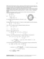
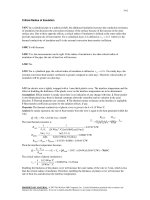
2-129 A spherical liquid nitrogen container is subjected to specified temperature on the inner surface and
convection on the outer surface. The mathematical formulation, the variation of temperature, and the rate of
evaporation of nitrogen are to be determined for steady one-dimensional heat transfer.
Assumptions 1 Heat conduction is steady and one-dimensional since there is no change with time and there
is thermal symmetry about the midpoint. 2 Thermal conductivity is constant. 3 There is no heat generation.
Properties The thermal conductivity of the tank is given to be k = 18 W/m⋅°C. Also, hfg = 198 kJ/kg for
nitrogen.
Analysis (a) Noting that heat transfer is one-dimensional in the radial r direction, the mathematical
formulation of this problem can be expressed as
d ⎛ 2 dT ⎞
⎜r
⎟=0
dr ⎠
dr ⎝
h
T∞
and
T (r1 ) = T1 = −196°C
N2 r1
dT ( r2 )
−k
= h[T ( r2 ) − T∞ ]
r2
r
-196°C
dr
(b) Integrating the differential equation once with respect to r gives
dT
r2
= C1
dr
Dividing both sides of the equation above by r to bring it to a readily integrable form and then integrating,
C
dT C1
= 2
→ T (r ) = − 1 + C 2
dr r
r
where C1 and C2 are arbitrary constants. Applying the boundary conditions give
C
r = r1:
T (r1 ) = − 1 + C 2 = T1
r1
⎛ C
⎞
C1
= h⎜⎜ − 1 + C2 − T∞ ⎟⎟
2
r2
⎝ r2
⎠
Solving for C1 and C2 simultaneously gives
r (T − T )
C
T1 − T∞ r2
C1 = 2 1 ∞
and C 2 = T1 + 1 = T1 +
r2
r
k
k r1
r1
1− −
1− 2 −
r1 hr2
r1 hr2
Substituting C1 and C2 into the general solution, the variation of temperature is determined to be
⎛ 1 1⎞
C
C
T1 − T∞ ⎛ r2 r2 ⎞
⎜ − ⎟ + T1
T ( r ) = − 1 + T1 + 1 = C1 ⎜⎜ − ⎟⎟ + T1 =
r
k ⎜⎝ r1 r ⎟⎠
r
r1
⎝ r1 r ⎠
1− 2 −
r1 hr2
−k
r = r2:
=
(−196 − 20)°C
2.1
18 W/m ⋅ °C
1−
−
2 (25 W/m 2 ⋅ °C)(2.1 m)
⎛ 2.1 2.1 ⎞
−
⎜
⎟ + (−196)°C = 549.8(1.05 − 2.1 / r ) − 196
r ⎠
⎝ 2
(c) The rate of heat transfer through the wall and the rate of evaporation of nitrogen are determined from
C
r (T − T )
dT
Q& = − kA
= −k (4πr 2 ) 21 = −4πkC1 = −4πk 2 1 ∞
r
k
dx
r
1− 2 −
r1 hr2
= −4π (18 W/m ⋅ °C)
m& =
(2.1 m)(−196 − 20)°C
= −261,200 W (to the tank since negative)
2.1
18 W/m ⋅ °C
1−
−
2 (25 W/m 2 ⋅ °C)(2.1 m)
Q&
261,200 J/s
=
= 1.32 kg/s
h fg 198,000 J/kg
PROPRIETARY MATERIAL. © 2007 The McGraw-Hill Companies, Inc. Limited distribution permitted only to teachers and
educators for course preparation. If you are a student using this Manual, you are using it without permission.
2-64
2-130 A spherical liquid oxygen container is subjected to specified temperature on the inner surface and
convection on the outer surface. The mathematical formulation, the variation of temperature, and the rate
of evaporation of oxygen are to be determined for steady one-dimensional heat transfer.
Assumptions 1 Heat conduction is steady and one-dimensional since there is no change with time and there
is thermal symmetry about the midpoint. 2 Thermal conductivity is constant. 3 There is no heat generation.
Properties The thermal conductivity of the tank is given to be k = 18 W/m⋅°C. Also, hfg = 213 kJ/kg for
oxygen.
Analysis (a) Noting that heat transfer is one-dimensional in the radial r direction, the mathematical
formulation of this problem can be expressed as
d ⎛ 2 dT ⎞
h
⎜r
⎟=0
dr ⎝
dr ⎠
T∞
O2 r1
and
T (r1 ) = T1 = −183°C
r
r2
-183°C
dT ( r2 )
−k
= h[T ( r2 ) − T∞ ]
dr
(b) Integrating the differential equation once with respect to r gives
dT
r2
= C1
dr
Dividing both sides of the equation above by r to bring it to a readily integrable form and then integrating,
C
dT C1
= 2
→ T (r ) = − 1 + C 2
dr r
r
where C1 and C2 are arbitrary constants. Applying the boundary conditions give
C
T (r1 ) = − 1 + C 2 = T1
r = r1:
r1
⎛ C
⎞
C1
= h⎜⎜ − 1 + C2 − T∞ ⎟⎟
2
r2
⎝ r2
⎠
Solving for C1 and C2 simultaneously gives
r (T − T )
C
T1 − T∞ r2
C1 = 2 1 ∞
and C 2 = T1 + 1 = T1 +
r2
r
k
k r1
r1
1− −
1− 2 −
r1 hr2
r1 hr2
Substituting C1 and C2 into the general solution, the variation of temperature is determined to be
⎛ 1 1⎞
C
C
T1 − T∞ ⎛ r2 r2 ⎞
⎜ − ⎟ + T1
T ( r ) = − 1 + T1 + 1 = C1 ⎜⎜ − ⎟⎟ + T1 =
r
k ⎜⎝ r1 r ⎟⎠
r
r1
⎝ r1 r ⎠
1− 2 −
r1 hr2
−k
r = r2:
=
(−183 − 20)°C
2.1
18 W/m ⋅ °C
1−
−
2 (25 W/m 2 ⋅ °C)(2.1 m)
⎛ 2.1 2.1 ⎞
−
⎜
⎟ + ( −183)°C = 516.7(1.05 − 2.1 / r ) − 183
r ⎠
⎝ 2
(c) The rate of heat transfer through the wall and the rate of evaporation of oxygen are determined from
C
r (T − T∞ )
dT
Q& = − kA
= − k (4πr 2 ) 21 = −4πkC1 = −4πk 2 1
r
k
dx
r
1− 2 −
r1 hr2
= −4π (18 W/m ⋅ °C)
m& =
(2.1 m)(−183 − 20)°C
= −245,450 W (to the tank since negative)
2.1
18 W/m ⋅ °C
1−
−
2 (25 W/m 2 ⋅ °C)(2.1 m)
Q&
245,450 J/s
=
= 1.15 kg/s
h fg 213,000 J/kg
PROPRIETARY MATERIAL. © 2007 The McGraw-Hill Companies, Inc. Limited distribution permitted only to teachers and
educators for course preparation. If you are a student using this Manual, you are using it without permission.
2-65
2-131 A large plane wall is subjected to convection, radiation, and specified temperature on the right
surface and no conditions on the left surface. The mathematical formulation, the variation of temperature
in the wall, and the left surface temperature are to be determined for steady one-dimensional heat transfer.
Assumptions 1 Heat conduction is steady and one-dimensional since the wall is large relative to its
thickness, and the thermal conditions on both sides of the wall are uniform. 2 Thermal conductivity is
constant. 3 There is no heat generation in the wall.
Properties The thermal conductivity and emissivity are given to be k = 8.4 W/m⋅°C and ε = 0.7.
Analysis (a) Taking the direction normal to the surface of the wall to be the x direction with x = 0 at the left
surface, and the mathematical formulation of this problem can be expressed as
d 2T
=0
dx 2
and
−k
dT ( L)
4
4
= h[T ( L) − T∞ ] + εσ [T ( L) 4 − Tsurr
] = h[T2 − T∞ ] + εσ [(T2 + 273) 4 − Tsurr
]
dx
T ( L) = T2 = 45°C
(b) Integrating the differential equation twice with respect to x yields
Tsurr
dT
= C1
dx
45°C
ε
T ( x) = C1x + C2
where C1 and C2 are arbitrary constants. Applying the boundary
conditions give
Convection at x = L
Temperature at x = L:
4
− kC1 = h[T2 − T∞ ] + εσ[(T2 + 273) 4 − Tsurr
]
4
→ C1 = −{h[T2 − T∞ ] + εσ[(T2 + 273) 4 − Tsurr
]} / k
h
T∞
L
x
T ( L) = C1 × L + C 2 = T2 → C 2 = T2 − C1 L
Substituting C1 and C2 into the general solution, the variation of temperature is determined to be
T ( x) = C1x + (T2 − C1L) = T2 − (L − x)C1 = T2 +
4
h[T2 − T∞ ] + εσ[(T2 + 273)4 − Tsurr
]
(L − x)
k
(14 W/m2 ⋅ °C)(45 − 25)°C + 0.7(5.67×10⁻⁸ W/m2 ⋅ K4 )[(318K)4 − (290K)4 ]
(0.4 − x) m
8.4 W/m⋅ °C
= 45 + 48.23(0.4 − x)
= 45°C +
(c) The temperature at x = 0 (the left surface of the wall) is
T (0) = 45 + 48.23(0.4 − 0) = 64.3°C
PROPRIETARY MATERIAL. © 2007 The McGraw-Hill Companies, Inc. Limited distribution permitted only to teachers and
educators for course preparation. If you are a student using this Manual, you are using it without permission.
2-66
2-132 The base plate of an iron is subjected to specified heat flux on the left surface and convection and
radiation on the right surface. The mathematical formulation, and an expression for the outer surface
temperature and its value are to be determined for steady one-dimensional heat transfer.
Assumptions 1 Heat conduction is steady and one-dimensional. 2 Thermal conductivity is constant. 3
There is no heat generation. 4 Heat loss through the upper part of the iron is negligible.
Properties The thermal conductivity and emissivity are given to be k = 18 W/m⋅°C and ε = 0.7.
Analysis (a) Noting that the upper part of the iron is well insulated
and thus the entire heat generated in the resistance wires is transferred
to the base plate, the heat flux through the inner surface is determined
to be
Q&
1000 W
q& 0 = 0 =
= 66,667 W/m 2
Abase 150 × 10 − 4 m 2
Tsurr
q
ε
Taking the direction normal to the surface of the wall to be the x
direction with x = 0 at the left surface, the mathematical formulation
of this problem can be expressed as
d 2T
dx 2
and
−k
=0
h
T∞
L
x
dT (0)
= q& 0 = 66,667 W/m 2
dx
dT ( L)
4
4
= h[T ( L) − T∞ ] + εσ [T ( L) 4 − Tsurr
] = h[T2 − T∞ ] + εσ [(T2 + 273) 4 − Tsurr
]
dx
(b) Integrating the differential equation twice with respect to x
yields
−k
dT
= C1
dx
T ( x) = C1x + C2
where C1 and C2 are arbitrary constants. Applying the boundary conditions give
q& 0
k
x = 0:
− kC1 = q& 0 → C1 = −
x = L:
4
− kC1 = h[T2 − T∞ ] + εσ [(T2 + 273)4 − Tsurr
]
Eliminating the constant C1 from the two relations above gives the following expression for the outer
surface temperature T2,
4
h(T2 − T∞ ) + εσ [(T2 + 273)4 − Tsurr
] = q&0
(c) Substituting the known quantities into the implicit relation above gives
(30 W/m 2 ⋅ °C)(T2 − 26) + 0.7(5.67 ×10 −8 W/m 2 ⋅ K 4 )[(T2 + 273) 4 − 295 4 ] = 66,667 W/m 2
Using an equation solver (or a trial and error approach), the outer surface temperature is determined from
the relation above to be
T2 = 759°C
PROPRIETARY MATERIAL. © 2007 The McGraw-Hill Companies, Inc. Limited distribution permitted only to teachers and
educators for course preparation. If you are a student using this Manual, you are using it without permission.
2-67
2-133 The base plate of an iron is subjected to specified heat flux on the left surface and convection and
radiation on the right surface. The mathematical formulation, and an expression for the outer surface
temperature and its value are to be determined for steady one-dimensional heat transfer.
Assumptions 1 Heat conduction is steady and one-dimensional. 2 Thermal conductivity is constant. 3
There is no heat generation. 4 Heat loss through the upper part of the iron is negligible.
Properties The thermal conductivity and emissivity are given to be k = 18 W/m⋅°C and ε = 0.7.
Analysis (a) Noting that the upper part of the iron is well insulated
and thus the entire heat generated in the resistance wires is transferred
to the base plate, the heat flux through the inner surface is determined
to be
Q&
1500 W
q& 0 = 0 =
= 100,000 W/m 2
Abase 150 ×10 − 4 m 2
Tsurr
q
ε
Taking the direction normal to the surface of the wall to be the x
direction with x = 0 at the left surface, the mathematical formulation
of this problem can be expressed as
d 2T
dx 2
and
−k
=0
h
T∞
L
x
dT (0)
= q& 0 = 100,000 W/m 2
dx
dT ( L )
4
4
= h[T ( L) − T∞ ] + εσ [T ( L ) 4 − Tsurr
] = h[T2 − T∞ ] + εσ [(T2 + 273) 4 − Tsurr
]
dx
(b) Integrating the differential equation twice with respect to x
yields
−k
dT
= C1
dx
T ( x) = C1x + C2
where C1 and C2 are arbitrary constants. Applying the boundary conditions give
q& 0
k
x = 0:
− kC1 = q& 0 → C1 = −
x = L:
4
− kC1 = h[T2 − T∞ ] + εσ [(T2 + 273)4 − Tsurr
]
Eliminating the constant C1 from the two relations above gives the following expression for the outer
surface temperature T2,
4
h(T2 − T∞ ) + εσ [(T2 + 273)4 − Tsurr
] = q&0
(c) Substituting the known quantities into the implicit relation above gives
(30 W/m 2 ⋅ °C)(T2 − 26) + 0.7(5.67 ×10 −8 W/m 2 ⋅ K 4 )[(T2 + 273) 4 − 295 4 ] = 100,000 W/m 2
Using an equation solver (or a trial and error approach), the outer surface temperature is determined from
the relation above to be
T2 = 896°C
PROPRIETARY MATERIAL. © 2007 The McGraw-Hill Companies, Inc. Limited distribution permitted only to teachers and
educators for course preparation. If you are a student using this Manual, you are using it without permission.
2-68
2-134E The concrete slab roof of a house is subjected to specified temperature at the bottom surface and
convection and radiation at the top surface. The temperature of the top surface of the roof and the rate of
heat transfer are to be determined when steady operating conditions are reached.
Assumptions 1 Steady operating conditions are reached. 2 Heat transfer is one-dimensional since the roof
area is large relative to its thickness, and the thermal conditions on both sides of the roof are uniform. 3
Thermal properties are constant. 4 There is no heat generation in the wall.
Properties The thermal conductivity and emissivity are given to be k = 1.1 Btu/h⋅ft⋅°F and ε = 0.8.
Analysis In steady operation, heat conduction through the roof must be equal to net heat transfer from the
outer surface. Therefore, taking the outer surface temperature of the roof to be T2 (in °F),
kA
T1 − T2
4
= hA(T2 − T∞ ) + εAσ [(T2 + 460) 4 − Tsky
]
L
Canceling the area A and substituting the known quantities,
(1.1 Btu/h ⋅ ft ⋅ °F)
x
L
T∞
h
Tsky
(62 − T2 )°F
= (3.2 Btu/h ⋅ ft 2 ⋅ °F)(T2 − 50)°F
0.8 ft
+ 0.8(0.1714 × 10 −8 Btu/h ⋅ ft 2 ⋅ R 4 )[(T2 + 460) 4 − 310 4 ]R 4
T1
Using an equation solver (or the trial and error method), the outer surface temperature is determined to be
T2 = 38°F
Then the rate of heat transfer through the roof becomes
T − T2
(62 − 38)°F
Q& = kA 1
= (1.1 Btu/h ⋅ ft ⋅ °F)(25 × 35 ft 2 )
= 28,875 Btu/h
0.8 ft
L
Discussion The positive sign indicates that the direction of heat transfer is from the inside to the outside.
Therefore, the house is losing heat as expected.
PROPRIETARY MATERIAL. © 2007 The McGraw-Hill Companies, Inc. Limited distribution permitted only to teachers and
educators for course preparation. If you are a student using this Manual, you are using it without permission.
2-69
2-135 The surface and interface temperatures of a resistance wire covered with a plastic layer are to be
determined.
Assumptions 1 Heat transfer is steady since there is no change with time. 2 Heat transfer is onedimensional since this two-layer heat transfer problem possesses symmetry about the center line and
involves no change in the axial direction, and thus T = T(r) . 3 Thermal conductivities are constant. 4 Heat
generation in the wire is uniform.
Properties It is given that k wire = 18 W/m ⋅ °C and k plastic = 1.8 W/m ⋅ °C .
Analysis Letting TI denote the unknown interface temperature, the mathematical formulation of the heat
transfer problem in the wire can be expressed as
1 d ⎛ dT ⎞ e&gen
=0
⎜r
⎟+
r dr ⎝ dr ⎠
k
with
T (r1 ) = TI
T∞
h
dT (0)
=0
dr
and
Multiplying both sides of the differential
equation by r, rearranging, and integrating give
e&gen
d ⎛ dT ⎞
r
⎜r
⎟=−
dr ⎝ dr ⎠
k
r1
r2
egen
e& gen r 2
dT
→ r
=−
+ C1 (a)
dr
k 2
Applying the boundary condition at the center (r = 0) gives
B.C. at r = 0:
0×
e& gen
dT (0)
=−
× 0 + C1
dr
2k
→ C1 = 0
Dividing both sides of Eq. (a) by r to bring it to a readily integrable form and integrating,
e& gen
dT
=−
r
dr
2k
→
T (r ) = −
e& gen
4k
r 2 + C2
(b)
Applying the other boundary condition at r = r1 ,
B. C. at r = r1 :
TI = −
e&gen
4k
r12 + C 2
→ C 2 = TI +
e& gen
4k
r12
Substituting this C 2 relation into Eq. (b) and rearranging give
Twire (r ) = TI +
e& gen
4k wire
(r12 − r 2 )
(c)
Plastic layer The mathematical formulation of heat transfer problem in the plastic can be expressed as
d ⎛ dT ⎞
⎜r
⎟=0
dr ⎝ dr ⎠
with
T (r1 ) = TI
and
−k
dT (r2 )
= h[T (r2 ) − T∞ ]
dr
The solution of the differential equation is determined by integration to be
r
dT
= C1
dr
→
dT C1
=
dr
r
→
T (r ) = C1 ln r + C 2
where C1 and C2 are arbitrary constants. Applying the boundary conditions give
r = r1:
C1 ln r1 + C 2 = T I
→ C 2 = T I − C1 ln r1
PROPRIETARY MATERIAL. © 2007 The McGraw-Hill Companies, Inc. Limited distribution permitted only to teachers and
educators for course preparation. If you are a student using this Manual, you are using it without permission.
r
2-70
−k
r = r2:
C1
= h[(C1 ln r2 + C2 ) − T∞ ]
r2
→
C1 =
T∞ − TI
r
k
ln 2 +
r1 hr2
Substituting C1 and C2 into the general solution, the variation of temperature in plastic is determined to be
Tplastic (r ) = C1 ln r + T I − C1 ln r1 = T I +
T∞ − T I
r
ln
k
r
r
plastic
1
ln 2 +
r1
hr2
We have already utilized the first interface condition by setting the wire and plastic layer temperatures
equal to TI at the interface r = r1 . The interface temperature TI is determined from the second interface
condition that the heat flux in the wire and the plastic layer at r = r1 must be the same:
− k wire
dTplastic (r1 )
e& gen r1
dTwire (r1 )
= −k plastic
→
= −k plastic
dr
dr
2
T∞ − TI
1
k
r
plastic r1
ln 2 +
r1
hr2
Solving for TI and substituting the given values, the interface temperature is determined to be
e& gen r12 ⎛ r2 k plastic
⎜ ln +
TI =
2k plastic ⎜⎝ r1
hr2
=
⎞
⎟ + T∞
⎟
⎠
(1.5 × 10 6 W/m 3 )(0.003 m) 2
2(1.8 W/m ⋅ °C)
⎞
⎛ 0.007 m
1.8 W/m ⋅ °C
⎟ + 25°C = 97.1°C
⎜ ln
+
2
⎜ 0.003 m (14 W/m ⋅ °C)(0.007 m) ⎟
⎠
⎝
Knowing the interface temperature, the temperature at the center line (r = 0) is obtained by substituting the
known quantities into Eq. (c),
Twire (0) = TI +
e&gen r12
4k wire
= 97.1°C +
(1.5 × 10⁶ W/m 3 )(0.003 m)2
= 97.3°C
4 × (18 W/m ⋅ °C)
Thus the temperature of the centerline will be slightly above the interface temperature.
PROPRIETARY MATERIAL. © 2007 The McGraw-Hill Companies, Inc. Limited distribution permitted only to teachers and
educators for course preparation. If you are a student using this Manual, you are using it without permission.
2-71
2-136 A cylindrical shell with variable conductivity is
subjected to specified temperatures on both sides. The rate of
heat transfer through the shell is to be determined.
Assumptions 1 Heat transfer is given to be steady and onedimensional. 2 Thermal conductivity varies quadratically. 3
There is no heat generation.
k(T)
T1
T2
Properties The thermal conductivity is given to be
k (T ) = k 0 (1 + βT 2 ) .
r2
r1
Analysis When the variation of thermal conductivity with
temperature k(T) is known, the average value of the thermal
conductivity in the temperature range between T1 and T2 is
determined from
r
T
k avg
∫
=
T2
k (T )dT
T1
∫
=
T2
T1
T2 − T1
(
2
k 0 (1 + β T )dT
T2 − T1
)
=
β
⎛
⎞ 2
k 0 ⎜T + T 3 ⎟
3
⎝
⎠ T1
T2 − T1
(
)
β
⎡
⎤
k 0 ⎢(T2 − T1 ) + T23 − T13 ⎥
3
⎣
⎦
=
T2 − T1
⎡ β
⎤
= k 0 ⎢1 + T22 + T1T2 + T12 ⎥
⎣ 3
⎦
This relation is based on the requirement that the rate of heat transfer through a medium with constant
average thermal conductivity k avg equals the rate of heat transfer through the same medium with variable
conductivity k(T).
Then the rate of heat conduction through the cylindrical shell can be determined from Eq. 2-77 to be
(
T − T2
⎡ β
Q& cylinder = 2πk avg L 1
= 2πk 0 ⎢1 + T22 + T1T2 + T12
ln(r2 / r1 )
⎣ 3
)⎤⎥ L ln(T r− /Tr )
1
⎦
2
2
1
Discussion We would obtain the same result if we substituted the given k(T) relation into the second part
of Eq. 2-77, and performed the indicated integration.
2-137 Heat is generated uniformly in a cylindrical uranium fuel rod. The temperature difference between
the center and the surface of the fuel rod is to be determined.
Assumptions 1 Heat transfer is steady since there is no indication of any change with time. 2 Heat transfer
is one-dimensional since there is thermal symmetry about the center line and no change in the axial
direction. 3 Thermal conductivity is constant. 4 Heat generation is uniform.
Properties The thermal conductivity of uranium at room temperature is k = 27.6 W/m⋅°C (Table A-3).
Analysis The temperature difference between the center
and the surface of the fuel rods is determined from
To − T s =
e& gen ro2
4k
=
(4 × 10 7 W/m 3 )(0.016 m) 2
= 92.8°C
4(27.6 W/m.°C)
Ts
e
D
PROPRIETARY MATERIAL. © 2007 The McGraw-Hill Companies, Inc. Limited distribution permitted only to teachers and
educators for course preparation. If you are a student using this Manual, you are using it without permission.
2-72
2-138 A large plane wall is subjected to convection on the inner and outer surfaces. The mathematical
formulation, the variation of temperature, and the temperatures at the inner and outer surfaces to be
determined for steady one-dimensional heat transfer.
Assumptions 1 Heat conduction is steady and one-dimensional. 2 Thermal conductivity is constant. 3
There is no heat generation.
Properties The thermal conductivity is given to be k = 0.77 W/m⋅°C.
Analysis (a) Taking the direction normal to the surface of the wall to be the x direction with x = 0 at the
inner surface, the mathematical formulation of this problem can be expressed as
d 2T
=0
dx 2
and
h1 [T∞1 − T (0)] = − k
−k
dT (0)
dx
dT ( L)
= h2 [T ( L) − T∞ 2 ]
dx
k
h2
T∞2
h1
T∞1
(b) Integrating the differential equation twice with respect to x yields
L
dT
= C1
dx
T ( x) = C1x + C2
where C1 and C2 are arbitrary constants. Applying the boundary conditions give
x = 0:
h1 [T∞1 − (C1 × 0 + C 2 )] = −kC1
x = L:
− kC1 = h2 [(C1 L + C 2 ) − T∞ 2 ]
Substituting the given values, these equations can be written as
5(27 − C 2 ) = −0.77C1
−0.77C1 = (12)(0.2C1 + C 2 − 8)
Solving these equations simultaneously give
C1 = −45.45
C 2 = 20
Substituting C1 and C 2 into the general solution, the variation of temperature is determined to be
T ( x) = 20 − 45.45 x
(c) The temperatures at the inner and outer surfaces are
T (0) = 20 − 45.45 × 0 = 20°C
T ( L) = 20 − 45.45 × 0.2 = 10.9°C
PROPRIETARY MATERIAL. © 2007 The McGraw-Hill Companies, Inc. Limited distribution permitted only to teachers and
educators for course preparation. If you are a student using this Manual, you are using it without permission.
2-73
2-139 A hollow pipe is subjected to specified temperatures at the inner and outer surfaces. There is also
heat generation in the pipe. The variation of temperature in the pipe and the center surface temperature of
the pipe are to be determined for steady one-dimensional heat transfer.
Assumptions 1 Heat conduction is steady and one-dimensional since the pipe is long relative to its
thickness, and there is thermal symmetry about the centerline. 2 Thermal conductivity is constant.
Properties The thermal conductivity is given to be k = 14 W/m⋅°C.
Analysis The rate of heat generation is determined from
W&
W&
25,000 W
e& gen =
=
=
= 26,750 W/m 3
2
2
2
V π ( D 2 − D1 ) L / 4 π (0.4 m) − (0.3 m) 2 (17 m) / 4
[
]
Noting that heat transfer is one-dimensional in the radial r direction, the mathematical formulation of this
problem can be expressed as
1 d ⎛ dT ⎞ e& gen
=0
⎜r
⎟+
r dr ⎝ dr ⎠
k
and
T (r1 ) = T1 = 60°C
egen
T ( r2 ) = T2 = 80°C
T1
Rearranging the differential equation
T2
d ⎛ dT ⎞ −e& gen r
=0
⎜r
⎟=
dr ⎝ dr ⎠
k
r1
r2
and then integrating once with respect to r,
r
2
dT − e&gen r
r
=
+ C1
dr
2k
Rearranging the differential equation again
dT −e& gen r C1
=
+
dr
2k
r
and finally integrating again with respect to r, we obtain
− e&gen r 2
T (r ) =
+ C1 ln r + C 2
4k
where C1 and C2 are arbitrary constants. Applying the boundary conditions give
− e& gen r1 2
r = r1:
T ( r1 ) =
+ C1 ln r1 + C 2
4k
− e& gen r2 2
r = r2:
T ( r2 ) =
+ C1 ln r2 + C 2
4k
Substituting the given values, these equations can be written as
− (26,750)(0.15) 2
60 =
+ C1 ln(0.15) + C 2
4(14)
80 =
− (26,750)(0.20) 2
+ C1 ln(0.20) + C 2
4(14)
Solving for C1 and C 2 simultaneously gives
C1 = 98.58
C 2 = 257.8
Substituting C1 and C 2 into the general solution, the variation of temperature is determined to be
− 26,750r 2
+ 98.58 ln r + 257.8 = 257.8 − 477.7r 2 + 98.58 ln r
4(14)
The temperature at the center surface of the pipe is determined by setting radius r to be 17.5 cm, which is
the average of the inner radius and outer radius.
T (r ) = 257.8 − 477.7(0.175) 2 + 98.58 ln(0.175) = 71.3°C
T (r ) =
PROPRIETARY MATERIAL. © 2007 The McGraw-Hill Companies, Inc. Limited distribution permitted only to teachers and
educators for course preparation. If you are a student using this Manual, you are using it without permission.
2-74
2-140 Heat is generated in a plane wall. Heat is supplied from one side which is insulated while the other
side is subjected to convection with water. The convection coefficient, the variation of temperature in the
wall, and the location and the value of the maximum temperature in the wall are to be determined.
Assumptions 1 Heat transfer is steady since there is no indication of any change with time. 2 Heat transfer
is one-dimensional since the wall is large relative to its thickness. 3 Thermal conductivity is constant. 4
Heat generation is uniform.
Analysis (a) Noting that the heat flux and the heat
generated will be transferred to the water, the heat
transfer coefficient is determined from the Newton’s
law of cooling to be
h=
Heater
q& s + e& gen L
T s − T∞
2
5
k
q& s
(16,000 W/m ) + (10 W/m )(0.04 m)
= 400 W/m 2 ⋅ °C
(90 − 40)°C
(b) The variation of temperature in the wall is in the
form of T(x) = ax2+bx+c. First, the coefficient a is
determined as follows
=
k
d 2T
dx 2
+ e& gen = 0
T∞ , h
Insulation
3
→
k
d 2T
dT 2
=−
Ts
e& gen x
L
e& gen
k
e& gen
e& gen 2
dT
=−
x+b
T =−
x + bx + c →
and
dx
k
2k
e&gen
10 5 W/m 3
a=−
=
= −2500°C/m 2
2k
2(20 W/m ⋅ °C)
Applying the first boundary condition:
x = 0,
T(0) = Ts → c = Ts = 90ºC
As the second boundary condition, we can use either
−k
dT
dx
(
x=L
(
)
⎛ e& gen L
⎞
1
1
+ b ⎟⎟ = q s → b = q s + e& gen L =
= − q s → k ⎜⎜ −
16000 + 10 5 × 0.04 = 1000°C/m
k
20
k
⎝
⎠
)
or
−k
dT
dx
x =0
= − h(Ts − T∞ )
k(a×0+b) = h(Ts -T∞) → b =
400
(90 − 40) = 1000°C/m
20
Substituting the coefficients, the variation of temperature becomes
T ( x) = −2500x 2 + 1000x + 90
(c) The x-coordinate of Tmax is xvertex= -b/(2a) = 1000/(2×2500) = 0.2 m = 20 cm. This is outside of the wall
boundary, to the left, so Tmax is at the left surface of the wall. Its value is determined to be
Tmax = T ( L) = −2500L2 + 1000L + 90 = −2500(0.04) 2 + 1000(0.04) + 90 = 126°C
The direction of qs(L) (in the negative x direction) indicates that at x = L the temperature increases in the
positive x direction. If a is negative, the T plot is like in Fig. 1, which shows Tmax at x=L. If a is positive,
the T plot could only be like in Fig. 2, which is incompatible with the direction of heat transfer at the
surface in contact with the water. So, temperature distribution can only be like in Fig. 1, where Tmax is at
x=L, and this was determined without using numerical values for a, b, or c.
PROPRIETARY MATERIAL. © 2007 The McGraw-Hill Companies, Inc. Limited distribution permitted only to teachers and
educators for course preparation. If you are a student using this Manual, you are using it without permission.
2-75
Slope
qs(L)
Fig. 1
qs(0)
Slope
qs(L)
Fig. 2
qs(0)
Here, heat transfer
and slope are
incompatible
This part could also be answered to without any information about the nature of the T(x) function, using
qualitative arguments only. At steady state, heat cannot go from right to left at any location. There is no
way out through the left surface because of the adiabatic insulation, so it would accumulate somewhere,
contradicting the steady state assumption. Therefore, the temperature must continually decrease from left to
right, and Tmax is at x = L.
PROPRIETARY MATERIAL. © 2007 The McGraw-Hill Companies, Inc. Limited distribution permitted only to teachers and
educators for course preparation. If you are a student using this Manual, you are using it without permission.
2-76
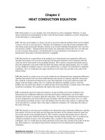
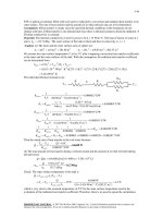
2-141 Heat is generated in a plane wall. The temperature distribution in the wall is given. The surface
temperature, the heat generation rate, the surface heat fluxes, and the relationship between these heat
fluxes, the heat generation rate, and the geometry of the wall are to be determined.
Assumptions 1 Heat transfer is steady since there is no indication of any change with time. 2 Heat transfer
is one-dimensional since the wall is large relative to its thickness. 3 Thermal conductivity is constant. 4
Heat generation is uniform.
Analysis (a) The variation of temperature is symmetric about x = 0. The surface temperature is
Ts = T ( L) = T (− L) = a − bL2 = 80°C − (2 ×10 4 °C/m 2 )(0.02 m) 2 = 72°C
The plot of temperatures across the wall thickness is given below.
82
80
72ºC
T [C]
72ºC
k
78
e&gen
76
T∞
h
74
72
-L
70
-0.02
-0.01
0
x [m]
0.01
x
L
0.02
(b) The volumetric rate of heat generation is
k
d 2T
dx 2
+ e& gen = 0 ⎯
⎯→ e& gen = − k (−2b) = 2(5 W/m ⋅ °C)(2 × 10 4 °C/m 2 ) = 2 × 10 5 W/m 3
(c) The heat fluxes at the two surfaces are
q& s ( L) = − k
dT
dx
= − k (−2bL) = 2(5 W/m ⋅ °C)(2 × 10 4 °C/m 2 )(0.02 m) = 4000 W/m 2
L
dT
q& s (− L) = − k
dx
= − k [(−2b(− L)] = −2(5 W/m ⋅ °C)(2 × 10 4 °C/m 2 )(0.02 m) = −4000 W/m 2
L
(d) The relationship between these fluxes, the heat generation rate and the geometry of the wall is
E& out = E& gen
[q& s ( L) + q& s (− L)]A = e&genV
[q& s ( L) + q& s (− L)]WH = e&gen (2 LWH )
q& s ( L) + q& s (− L) = 2e& gen L
Discussion Note that in this relation the absolute values of heat fluxes should be used. Substituting
numerical values gives 8000 W/m2 on both sides of the equation, and thus verifying the relationship.
PROPRIETARY MATERIAL. © 2007 The McGraw-Hill Companies, Inc. Limited distribution permitted only to teachers and
educators for course preparation. If you are a student using this Manual, you are using it without permission.
2-77
2-142 Steady one-dimensional heat conduction takes place in a long slab. It is to be shown that the heat
*
k * ⎛⎜ T + T0 ⎞⎟
ln *
flux in steady operation is given by q& =
. Also, the heat flux is to be calculated for a given
W ⎜⎝ T + Tw ⎟⎠
set of parameters.
Assumptions 1 Heat transfer is steady. 2 Heat transfer is one-dimensional since the wall is large relative to
its thickness.
Analysis The derivation is given as follows
q& = −k
or
∫
Tw
T0
dT
T * +T
ln(T * + T )
Tw
T0
⎛T * +T
ln⎜ * w
⎜ T +T
0
⎝
=−
=−
− k * dT
dT
= *
dx (T + T ) dx
q&
W
k*
∫ dx
q&
(W − 0)
k*
0
⎞
⎟ = −q& W
⎟
k*
⎠
*
k * ⎛⎜ T + T0
q& =
ln *
W ⎜⎝ T + Tw
⎞
⎟
⎟
⎠
The heat flux for the given values is
q& =
*
k * ⎛⎜ T + T0
ln *
W ⎜⎝ T + Tw
⎞ 7 × 10 4 W/m ⎛ (1000 − 600)K ⎞
⎟=
⎟⎟ = −1.42 × 10 5 W/m 2
ln⎜⎜
⎟
0.2
m
(
1000
−
400
)
K
⎝
⎠
⎠
2-143 A spherical ball in which heat is generated uniformly is exposed to iced-water. The temperatures at
the center and at the surface of the ball are to be determined.
Assumptions 1 Heat transfer is steady since there is no indication of any change with time. 2 Heat transfer
is one-dimensional., and there is thermal symmetry about the center point. 3 Thermal conductivity is
constant. 4 Heat generation is uniform.
Properties The thermal conductivity is given to be k = 45 W/m⋅°C.
Analysis The temperatures at the center and at the surface of the ball are
determined directly from
T s = T∞ +
T0 = T s +
e& gen ro
3h
e& gen ro2
6k
= 0°C +
(2.6 × 10 6 W/m 3 )(0.12 m)
= 86.7°C +
3(1200 W/m 2 .°C)
= 86.7°C
D
h
T∞
e&gen
(2.6 × 10 6 W/m 3 )(0.12 m) 2
= 225°C
6(45 W/m.°C)
PROPRIETARY MATERIAL. © 2007 The McGraw-Hill Companies, Inc. Limited distribution permitted only to teachers and
educators for course preparation. If you are a student using this Manual, you are using it without permission.
2-78
Fundamentals of Engineering (FE) Exam Problems
2-144 The heat conduction equation in a medium is given in its simplest form as
1 d ⎛ dT ⎞
⎜ rk
⎟ + e& gen = 0
r dr ⎝ dr ⎠
Select the wrong statement below.
(a) the medium is of cylindrical shape.
(b) the thermal conductivity of the medium is constant.
(c) heat transfer through the medium is steady.
(d) there is heat generation within the medium.
(e) heat conduction through the medium is one-dimensional.
Answer (b) thermal conductivity of the medium is constant
2-145 Consider a medium in which the heat conduction equation is given in its simplest form as
1 ∂ ⎛ 2 ∂T ⎞ 1 ∂T
⎜r
⎟=
∂r ⎠ α ∂t
r 2 ∂r ⎝
(a) Is heat transfer steady or transient?
(b) Is heat transfer one-, two-, or three-dimensional?
(c) Is there heat generation in the medium?
(d) Is the thermal conductivity of the medium constant or variable?
(e) Is the medium a plane wall, a cylinder, or a sphere?
(f) Is this differential equation for heat conduction linear or nonlinear?
Answers: (a) transient, (b) one-dimensional, (c) no, (d) constant, (e) sphere, (f) linear
2-146 An apple of radius R is losing heat steadily and uniformly from its outer surface to the ambient air at
temperature T∞ with a convection coefficient of h, and to the surrounding surfaces at temperature Tsurr (all
temperatures are absolute temperatures). Also, heat is generated within the apple uniformly at a rate of
e&gen per unit volume. If Ts denotes the outer surface temperature, the boundary condition at the outer
surface of the apple can be expressed as
(a) − k
dT
dr
r=R
4
= h(T s − T∞ ) + εσ (Ts4 − Tsurr
)
dT
4
= h(T s − T∞ ) + εσ (Ts4 − Tsurr
)
dr r = R
(e) None of them
(c) k
Answer: − k
dT
dr
r=R
(b) − k
(d) k
dT
dr
dT
dr
r=R
r=R
4
= h(T s − T∞ ) + εσ (T s4 − Tsurr
) + e& gen
4
= h(Ts − T∞ ) + εσ (Ts4 − Tsurr
)+
4πR 3 / 3
4πR 2
e& gen
4
= h(T s − T∞ ) + εσ (Ts4 − Tsurr
)
Note: Heat generation in the medium has no effect on boundary conditions.
PROPRIETARY MATERIAL. © 2007 The McGraw-Hill Companies, Inc. Limited distribution permitted only to teachers and
educators for course preparation. If you are a student using this Manual, you are using it without permission.
2-79
2-147 A furnace of spherical shape is losing heat steadily and uniformly from its outer surface of radius R
to the ambient air at temperature T∞ with a convection coefficient of h, and to the surrounding surfaces at
temperature Tsurr (all temperatures are absolute temperatures). If To denotes the outer surface temperature,
the boundary condition at the outer surface of the furnace can be expressed as
(a) − k
(c) k
dT
dr
dT
dr
r =R
r=R
(e) k (4πR 2 )
4
= h(To − T∞ ) + εσ (To4 − Tsurr
) (b) − k
4
= h(To − T∞ ) + εσ (To4 − Tsurr
)
dT
dr
Answer (a) − k
r =R
dT
dr
(d) k
dT
dr
dT
dr
r =R
r=R
4
= h(To − T∞ ) − εσ (To4 − Tsurr
)
4
= h(To − T∞ ) − εσ (To4 − Tsurr
)
4
= h(To − T∞ ) + εσ (To4 − Tsurr
)
r =R
4
= h(To − T∞ ) + εσ (To4 − Tsurr
)
2-148 A plane wall of thickness L is subjected to convection at both surfaces with ambient temperature T∞1
and heat transfer coefficient h1 at inner surface, and corresponding T∞2 and h2 values at the outer surface.
Taking the positive direction of x to be from the inner surface to the outer surface, the correct expression
for the convection boundary condition is
dT (0)
dT ( L)
(a) k
(b) k
= h1 [T (0) − T∞1 )]
= h2 [T ( L) − T∞ 2 )]
dx
dx
dT (0)
dT ( L )
(d) − k
(c) − k
= h1 [T∞1 − T∞ 2 )]
= h2 [T∞1 − T∞ 2 )]
dx
dx
(e) None of them
Answer (a) k
dT (0)
= h1 [T (0) − T∞1 )]
dx
2-149 Consider steady one-dimensional heat conduction through a plane wall, a cylindrical shell, and a
spherical shell of uniform thickness with constant thermophysical properties and no thermal energy
generation. The geometry in which the variation of temperature in the direction of heat transfer be linear is
(a) plane wall
(b) cylindrical shell
(c) spherical shell
(d) all of them
(e) none of them
Answer (a) plane wall
PROPRIETARY MATERIAL. © 2007 The McGraw-Hill Companies, Inc. Limited distribution permitted only to teachers and
educators for course preparation. If you are a student using this Manual, you are using it without permission.
2-80
2-150 Consider a large plane wall of thickness L, thermal conductivity k, and surface area A. The left
surface of the wall is exposed to the ambient air at T∞ with a heat transfer coefficient of h while the right
surface is insulated. The variation of temperature in the wall for steady one-dimensional heat conduction
with no heat generation is
h( L − x )
k
T∞
(b) T ( x) =
(a) T ( x) =
T∞
k
h( x + 0.5L)
⎛ xh ⎞
(c) T ( x) = ⎜1 − ⎟T∞
k ⎠
⎝
(d) T ( x) = ( L − x)T∞
(e) T ( x) = T∞
Answer (e) T ( x) = T∞
2-151 The variation of temperature in a plane wall is determined to be T(x)=65x+25 where x is in m and T
is in °C. If the temperature at one surface is 38ºC, the thickness of the wall is
(a) 2 m
(b) 0.4 m
(c) 0.2 m
(d) 0.1 m
(e) 0.05 m
Answer (c) 0.2 m
Solution Solved by EES Software. Solutions can be verified by copying-and-pasting the following lines on
a blank EES screen.
38=65*L+25
2-152 The variation of temperature in a plane wall is determined to be T(x)=110-48x where x is in m and T
is in °C. If the thickness of the wall is 0.75 m, the temperature difference between the inner and outer
surfaces of the wall is
(a) 110ºC
(b) 74ºC
(c) 55ºC
(d) 36ºC
(e) 18ºC
Answer (d) 36ºC
Solution Solved by EES Software. Solutions can be verified by copying-and-pasting the following lines on
a blank EES screen.
T1=110 [C]
L=0.75
T2=110-48*L
DELTAT=T1-T2
PROPRIETARY MATERIAL. © 2007 The McGraw-Hill Companies, Inc. Limited distribution permitted only to teachers and
educators for course preparation. If you are a student using this Manual, you are using it without permission.
2-81
2-153 The temperatures at the inner and outer surfaces of a 15-cm-thick plane wall are measured to be
40ºC and 28ºC, respectively. The expression for steady, one-dimensional variation of temperature in the
wall is
(a) T ( x) = 28 x + 40
(b) T ( x) = −40 x + 28
(c) T ( x) = 40 x + 28
(d) T ( x) = −80 x + 40
(e) T ( x) = 40 x − 80
Answer (d) T ( x) = −80 x + 40
Solution Solved by EES Software. Solutions can be verified by copying-and-pasting the following lines on
a blank EES screen.
T1=40 [C]
T2=28 [C]
L=0.15 [m]
"T(x)=C1x+C2"
C2=T1
T2=C1*L+T1
2-154 Heat is generated in a long 0.3-cm-diameter cylindrical electric heater at a rate of 150 W/cm3. The
heat flux at the surface of the heater in steady operation is
(a) 42.7 W/cm2
(b) 159 W/cm2
(c) 150 W/cm2
(d) 10.6 W/cm2
(e) 11.3 W/cm2
Answer (e) 11.3 W/cm2
Solution Solved by EES Software. Solutions can be verified by copying-and-pasting the following lines on
a blank EES screen.
"Consider a 1-cm long heater:"
L=1 [cm]
e=150 [W/cm^3]
D=0.3 [cm]
V=pi*(D^2/4)*L
A=pi*D*L "[cm^2]”
Egen=e*V "[W]"
Qflux=Egen/A "[W/cm^2]"
“Some Wrong Solutions with Common Mistakes:”
W1=Egen "Ignoring area effect and using the total"
W2=e/A "Threating g as total generation rate"
W3=e “ignoring volume and area effects”
PROPRIETARY MATERIAL. © 2007 The McGraw-Hill Companies, Inc. Limited distribution permitted only to teachers and
educators for course preparation. If you are a student using this Manual, you are using it without permission.
2-82
2-155 Heat is generated in a 8-cm-diameter spherical radioactive material whose thermal conductivity is 25
W/m.°C uniformly at a rate of 15 W/cm3. If the surface temperature of the material is measured to be
120°C, the center temperature of the material during steady operation is
(a) 160°C
(b) 280°C
(c) 212°C
(d) 360°C
(e) 600°C
Answer (b) 280°C
D=0.08
Ts=120
k=25
e_gen=15E+6
T=Ts+g*(D/2)^2/(6*k)
“Some Wrong Solutions with Common Mistakes:”
W1_T= e_gen*(D/2)^2/(6*k) "Not using Ts"
W2_T= Ts+e_gen*(D/2)^2/(4*k) "Using the relation for cylinder"
W3_T= Ts+e_gen*(D/2)^2/(2*k) "Using the relation for slab"
2-156 Heat is generated in a 3-cm-diameter spherical radioactive material uniformly at a rate of 15 W/cm3.
Heat is dissipated to the surrounding medium at 25°C with a heat transfer coefficient of 120 W/m2⋅°C. The
surface temperature of the material in steady operation is
(a) 56°C
(b) 84°C
(c) 494°C
(d) 650°C
(e) 108°C
Answer (d) 650°C
Solution Solved by EES Software. Solutions can be verified by copying-and-pasting the following lines on
a blank EES screen.
h=120 [W/m^2-C]
e=15 [W/cm^3]
Tinf=25 [C]
D=3 [cm]
V=pi*D^3/6 "[cm^3]"
A=pi*D^2/10000 "[m^2]"
Egen=e*V "[W]"
Qgen=h*A*(Ts-Tinf)
PROPRIETARY MATERIAL. © 2007 The McGraw-Hill Companies, Inc. Limited distribution permitted only to teachers and
educators for course preparation. If you are a student using this Manual, you are using it without permission.
2-83
2-157 Heat is generated uniformly in a 4-cm-diameter, 16-cm-long solid bar (k = 2.4 W/m⋅ºC). The
temperatures at the center and at the surface of the bar are measured to be 210ºC and 45ºC, respectively.
The rate of heat generation within the bar is
(a) 240 W
(b) 796 W
b) 1013 W
(c) 79,620 W
(d) 3.96×10⁶ W
Answer (b) 796 W
Solution Solved by EES Software. Solutions can be verified by copying-and-pasting the following lines on
a blank EES screen.
D=0.04 [m]
L=0.16 [m]
k=2.4 [W/m-C]
T0=210 [C]
T_s=45 [C]
T0-T_s=(e*(D/2)^2)/(4*k)
V=pi*D^2/4*L
E_dot_gen=e*V
"Some Wrong Solutions with Common Mistakes"
W1_V=pi*D*L "Using surface area equation for volume"
W1_E_dot_gen=e*W14_1
T0=(W2_e*(D/2)^2)/(4*k) "Using center temperature instead of temperature difference"
W2_Q_dot_gen=W2_e*V
W3_Q_dot_gen=e "Using heat generation per unit volume instead of total heat generation as the
result"
2-158 A solar heat flux q& s is incident on a sidewalk whose thermal conductivity is k, solar absorptivity is
αs and convective heat transfer coefficient is h. Taking the positive x direction to be towards the sky and
disregarding radiation exchange with the surroundings surfaces, the correct boundary condition for this
sidewalk surface is
(a) − k
dT
= α s q& s
dx
(b) − k
dT
= h(T − T∞ )
dx
(c) − k
dT
= h(T − T∞ ) − α s q& s
dx
(d) h(T − T∞ ) = α s q& s (e) None of them
Answer (c) − k
dT
= h(T − T∞ ) − α s q& s
dx
PROPRIETARY MATERIAL. © 2007 The McGraw-Hill Companies, Inc. Limited distribution permitted only to teachers and
educators for course preparation. If you are a student using this Manual, you are using it without permission.
2-84
2-159 Hot water flows through a PVC (k = 0.092 W/m⋅K) pipe whose inner diameter is 2 cm and outer
diameter is 2.5 cm. The temperature of the interior surface of this pipe is 35oC and the temperature of the
exterior surface is 20oC. The rate of heat transfer per unit of pipe length is
(a) 22.8 W/m
(b) 38.9 W/m
(c) 48.7 W/m
(d) 63.6 W/m
(e) 72.6 W/m
Answer (b) 38.9 W/m
Solution Solved by EES Software. Solutions can be verified by copying-and-pasting the following lines on
a blank EES screen.
do=2.5 [cm]
di=2.0 [cm]
k=0.092 [W/m-C]
T2=35 [C]
T1=20 [C]
Q=2*pi*k*(T2-T1)/LN(do/di)
2-160 The thermal conductivity of a solid depends upon the solid’s temperature as k = aT + b where a and
b are constants. The temperature in a planar layer of this solid as it conducts heat is given by
(a) aT + b = x + C2
(b) aT + b = C1x2 + C2
(c) aT2 + bT = C1x + C2
(d) aT2 + bT = C1x2 + C2 (e) None of them
Answer (c) aT2 + bT = C1x + C2
2-161 Harvested grains, like wheat, undergo a volumetric exothermic reaction while they are being stored.
This heat generation causes these grains to spoil or even start fires if not controlled properly. Wheat (k =
0.5 W/m⋅K) is stored on the ground (effectively an adiabatic surface) in 5-m thick layers. Air at 20°C
contacts the upper surface of this layer of wheat with h = 3 W/m2⋅K. The temperature distribution inside
this layer is given by
T − Ts
⎛x⎞
= 1− ⎜ ⎟
T0 − T s
⎝L⎠
2
where Ts is the upper surface temperature, T0 is the lower surface temperature, x is measured upwards from
the ground, and L is the thickness of the layer. When the temperature of the upper surface is 24oC, what is
the temperature of the wheat next to the ground?
(a) 39oC
(b) 51oC
(c) 72oC
(d) 84oC
(e) 91°C
Answer (d) 84oC
k=0.5 [W/m-K]
h=3 [W/m2-K]
L=5[m]
Ts=24 [C]
Ta=20 [C]
To=(h*L/(2*k))*(Ts-Ta)+Ts
PROPRIETARY MATERIAL. © 2007 The McGraw-Hill Companies, Inc. Limited distribution permitted only to teachers and
educators for course preparation. If you are a student using this Manual, you are using it without permission.
2-85
2-162 The conduction equation boundary condition for an adiabatic surface with direction n being normal
to the surface is
(a) T = 0 (b) dT/dn = 0
(c) d2T/dn2 = 0
(d) d3T/dn3 = 0
(e) -kdT/dn = 1
Answer (b) dT/dn = 0
2-163 Which one of the followings is the correct expression for one-dimensional, steady-state, constant
thermal conductivity heat conduction equation for a cylinder with heat generation?
(a)
1 ∂ ⎛ ∂T ⎞
∂T
⎜ rk
⎟ + e& gen = ρc
r ∂r ⎝ ∂r ⎠
∂t
(b)
1 ∂ ⎛ ∂T ⎞ e& gen 1 ∂T
=
⎜r
⎟+
r ∂r ⎝ ∂r ⎠
k
α ∂t
(c)
1 ∂ ⎛ ∂T ⎞ 1 ∂T
⎜r
⎟=
r ∂r ⎝ ∂r ⎠ α ∂t
(d)
1 d ⎛ dT ⎞ e&gen
=0
⎜r
⎟+
r dr ⎝ dr ⎠
k
Answer (d)
(e)
d ⎛ dT ⎞
⎜r
⎟=0
dr ⎝ dr ⎠
1 d ⎛ dT ⎞ e&gen
=0
⎜r
⎟+
r dr ⎝ dr ⎠
k
2-164 .... 2-167 Design and Essay Problems
KJ
PROPRIETARY MATERIAL. © 2007 The McGraw-Hill Companies, Inc. Limited distribution permitted only to teachers and
educators for course preparation. If you are a student using this Manual, you are using it without permission.